
文章目录
| 平台 | 内核版本 | 安卓版本 |
|---|---|---|
| RK3399 | Linux4.4 | Android7.1 |
本质上,Device Tree改变了原来用hardcode方式将HW 配置信息嵌入到内核代码的方法,改用bootloader传递一个DB的形式。对于基于ARM CPU的嵌入式系统,我们习惯于针对每一个platform进行内核的编译。但是随着ARM在消费类电子上的广泛应用(甚至桌面系统、服务器系统),我们期望ARM能够象X86那样用一个kernel image来支持多个platform。在这种情况下,如果我们认为kernel是一个black box,那么其输入参数应该包括:
- 识别
platform的信息 runtime的配置参数- 设备的拓扑结构以及特性
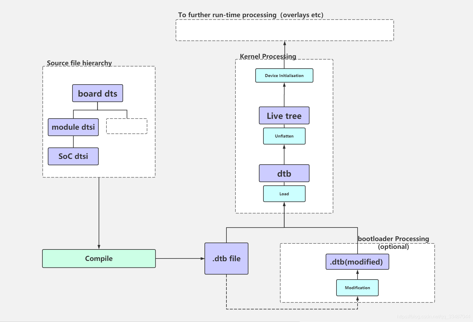
对于嵌入式系统,在系统启动阶段,bootloader会加载内核并将控制权转交给内核,此外,还需要把上述的三个参数信息传递给kernel如上图,以便kernel可以有较大的灵活性。在linux kernel中,Device Tree的设计目标就是如此。
1、device Tree包含的硬件信息有哪些?(海纳百川?)
Device Tree是否可以描述所有的硬件信息?
答案是不行的,因为基本上,那些可以动态探测到的设备是不需要描述的,例如USB device。不过对于SOC上的usb host controller,它是无法动态识别的,需要在device tree中描述。同样的道理,在computer system中,PCI device可以被动态探测到,不需要在device tree中描述,但是PCI bridge如果不能被探测,那么就需要描述之。 需要描述的内容一般包括:
CPUsMemoryBusesPeripheral connectionsInterrupt ControllersGPIO controllersClock controllers
2、Device Tree示例 (线头)
为了了解Device Tree的结构,我们首先给出一个Device Tree的示例:
最重要的属性 compatible, reg, clocks,interrupts, and status。

下面我们一起对其解析:
3、Device Tree语法解析(药引子)
其实DeviceTree的结构非常简单,由两种元素组成:Node(节点)、Property(属性)。
从上图中可以看出,device tree的基本单元是node。系统中的每个设备用一个node来描述,这些node被组织成树状结构,除了root node,每个node都只有一个parent。一个device tree文件中只能有一个root node。每个node中包含了若干的property/value来描述该node的一些特性。每个node用节点名字(node name)标识,节点名字的格式是:
node-name说明了何种设备,必须使用字符开头unit-address访问此设备的主地址,必须唯一,必须和此节点的reg属性的开始地址一致
	[label:] node-name[@unit-address] {


		[properties definitions]
		[child nodes]
	}
“[]”表示option,因此可以定义一个只有node name的空节点。label方便在dts文件中引用。child node的格式和node是完全一样的,因此,一个dts文件中就是若干嵌套组成的node,property以及child note、child note property描述。

注意:
如果该node没有reg属性,那么该节点名字中必须不能包括@和unit-address,例如上图spi0总线下的device child node。unit-address的具体格式是和设备挂在那个bus上相关。例如对于cpu,其unit-address就是从0开始编址,以此加一。而具体的设备,例如以太网控制器,其unit-address就是寄存器地址。root node的node name是确定的,必须是“/”。
4、特殊节点的介绍

4.1、根节点root node
只能有一个root node,它用来描述从CPU端看到的地址空间,至少需要用cpu和memory节点组成,如下:
/ {


	compatible = "rockchip,rk3399";

	interrupt-parent = <&gic>;
	#address-cells = <2>;
	#size-cells = <2>;
	cpus {


		......
	}
4.2、别名节点
aliases 节点定义了一些别名。为何要定义这个node呢?因为Device tree是树状结构,当要引用一个node的时候要指明相对于root node的full path,例如/node1/child-node1。如果多次引用,每次都要写这么复杂的字符串多少是有些麻烦,因此可以在aliases节点定义一些设备节点full path的缩写。

4.3、CPU节点
对于根节点,必须有一个cpus的child node来描述系统中的CPU信息。
	cpus {


		#address-cells = <2>;
		#size-cells = <0>;

		cpu_l0: cpu@0 {


			device_type = "cpu";
			compatible = "arm,cortex-a53", "arm,armv8";
			reg = <0x0 0x0>;
			enable-method = "psci";
			#cooling-cells = <2>; /* min followed by max */
			clocks = <&cru ARMCLKL>;
			dynamic-power-coefficient = <100>;
		};
4.4、Memory节点
memory device node是所有设备树文件的必备节点,它定义了系统物理内存的layout。device_type属性定义了该node的设备类型,例如cpu、serial等。对于memory node,其device_type必须等于memory。reg属性定义了访问该device node的地址信息,该属性的值被解析成任意长度的(address,size)数组,具体用多长的数据来表示address和size是在其parent node中定义(#address-cells和#size-cells)。对于device node,reg描述了memory-mapped IO register的offset和length。对于memory node,定义了该memory的起始地址和长度。
4.5、可选节点
chosen node主要用来描述由系统firmware指定的runtime parameter。如果存在chosen这个node,其parent node必须是名字是“/”的根节点。原来通过tag list传递的一些linux kernel的运行时参数可以通过Device Tree传递。例如command line可以通过bootargs这个property这个属性传递;initrd的开始地址也可以通过linux,initrd-start这个property这个属性传递。在实际中,建议增加一个bootargs的属性,例如:
chosen {

            bootargs = "console=ttymxc0,115200";    };
我们知道,device tree用于HW platform识别,runtime parameter传递以及硬件设备描述。chosen节点并没有描述任何硬件设备节点的信息,它只是传递了runtime parameter。
5、属性

5.1、Compatible属性和model属性
“compatible”属性通常用来device和driver的适配,推荐的格式为”manufacturer,model”“model”属性只是简单的表示型号,root节点用其来传递值给machine_desc_str
5.2、属性标签

5.3、寻址属性
如果一个device node中包含了有寻址需求(要定义reg property)的sub node(后文也许会用child node,和sub node是一样的意思),那么就必须要定义这两个属性。
#address-cells
defines the number of cells used to encode the address field in a child node’s reg property#size-cells
property defines the number of cells used to encode the size field in a child node’s reg property.
其中“#”是number的意思,#address-cells这个属性是用来描述sub node中的reg属性的地址域特性的,也就是说需要用多少个u32的cell来描述该地址域。
reg = <address1 length1 [address2 length2] [address3 length3] ... >
在 spi 节点中,#address-cells 设置为 1,#size-cells 设置为 0。

5.4、中断
| 属性 | 含义 |
|---|---|
interrupt-controller |
a property of the interrupt controller node. It states how many cells are in an interrupt specifier for this interrupt controller (Similar to #address-cells and #size-cells). |
#interrupt-cells |
a property of the interrupt controller node. It states how many cells are in an interrupt specifier for this interrupt controller (Similar to #address-cells and #size-cells). |
interrupt-parent |
A property of a device node containing a list of interrupt specifiers, one for each interrupt output signal on the device. |
interrupts |
A property of a device node containing a list of interrupt specifiers, one for each interrupt output signal on the device. |
具体各个HW block的interrupt source是如何物理的连接到interruptcontroller的呢?在dts文件中是用interrupt-parent这个属性来标识的。且慢,这里定义interrupt-parent属性的是root node,难道root node会产生中断到interrupt controller吗?当然不会,只不过如果一个能够产生中断的device node没有定义interrupt-parent的话,其interrupt-parent属性就是跟随parent node。因此,与其在所有的下游设备中定义interrupt-parent,不如统一在root node中定义了。
intc是一个lable,标识了一个device node(在本例中是标识了intc: interrupt-controller@00a01000这个device node)。实际上,interrupt-parent属性值应该是是一个u32的整数值(这个整数值在Device Tree的范围内唯一识别了一个device node,也就是phandle),不过,在dts文件中中,可以使用类似c语言的Labels and References机制。定义一个lable,唯一标识一个node或者property,后续可以使用&来引用这个lable。DTC会将lable转换成u32的整数值放入到DTB中,用户层面就不再关心具体转换的整数值了。
关于interrupt,我们值得进一步描述。在Device Tree中,有一个概念叫做interrupt tree,也就是说interrupt也是一个树状结构。我们以下图为例(该图来自Power_ePAPR_APPROVED_v1.1):

5.5、节点状态
可以使用okay和disabled来打开和注掉某一个驱动的设备注册。