写在前面
此系列相关博文:
Verilog初级教程(5)Verilog中的多维数组和存储器
Verilog初级教程(2)Verilog HDL的初级语法
FPGA/ASIC初学者应该学习Verilog还是VHDL?
-
个人微信公众号: FPGA LAB
-
注:学习交流使用!
正文
Verilog例化方式分为两种,一种是按端口定义时的顺序例化,一种是按端口名来例化。
下面将带来这些内容的叙述以及对比,还有如何处理空置的端口等。
按顺序排列的端口连接
按顺序排列的端口连接是例化的第一种方式,并不推荐,但是必须知道,因为还是有一些代码使用这种例化方式。
如下,如果我设计了一个模块:
module mydesign ( input  x, y, z,     // x is at position 1, y at 2, x at 3 and
                    output o);          // o is at position 4

  endmodule
那么按端口顺序例化的话,如下所示:
  module tb_top;
    wire [1:0]  a;
    wire        b, c;

    mydesign d0  (a[0], b, a[1], c);  // a[0] is at position 1 so it is automatically connected to x
                                      // b is at position 2 so it is automatically connected to y
                                      // a[1] is at position 3 so it is connected to z
                                      // c is at position 4, and hence connection is with o
  endmodule
按名称排列的端口连接
还是按上面那个例子,我定了一个模块:
module mydesign ( input  x, y, z,     // x is at position 1, y at 2, x at 3 and
                    output o);          // o is at position 4

  endmodule
如果按端口名字例化,如下:
  module tb_top;
    wire [1:0]  a;
    wire        b, c;
	mydesign d0(
	.x(a[0]),
	.y(b),
	.z(a[1]),
	.o(c)
	);

  endmodule
我们推荐使用按名字进行例化的方式,因为这种方式不考虑顺序,不容易出错。
一般自动生成例化模板的软件或插件,也几乎全是生成这种例化模板的。如果生成按顺序例化的模板,那也就注定黄了。
这些都不是重点,重点是下一个话题,我们在做实际项目中也会常常看看有未连接的端口,我们如何认为呢?或者如何处理呢?
未连接/悬空端口处理
未连接到例化模块中的端口按高阻态处理。如下:
还是拿上面设计的模块为例:
module mydesign ( input  x, y, z,     // x is at position 1, y at 2, x at 3 and
                    output o);          // o is at position 4

  endmodule
我们对这个模块进行例化使用:
module design_top(
	input [1:0] a,
	output c
);
  mydesign d0   (              // x is an input and not connected, hence a[0] will be Z
                .y (a[1]),
                .z (a[1]),
                .o ());        // o has valid value in mydesign but since
                               // it is not connected to "c" in design_top, c will be Z
endmodule
可以看到端口x,就连写都没写,因此,可以认为是一个未连接的悬空端口,是一个高阻态;
端口o,虽然写了,但是也没连接到顶层模块中的任意一个端口上,因此顶层的端口c也是一个高阻态。
下面举一个移位寄存器的例子,看看有些端口未连接,生成的硬件原理图是什么样的。
先从一个触发器看起:
// Module called "dff" has 3 inputs and 1 output port
module dff (   input       d,
              input       clk,
              input       rstn,
              output reg  q);

  // Contents of the module
  always @ (posedge clk) begin
    if (!rstn)
      q <= 0;
    else
      q <= d;
  end
endmodule
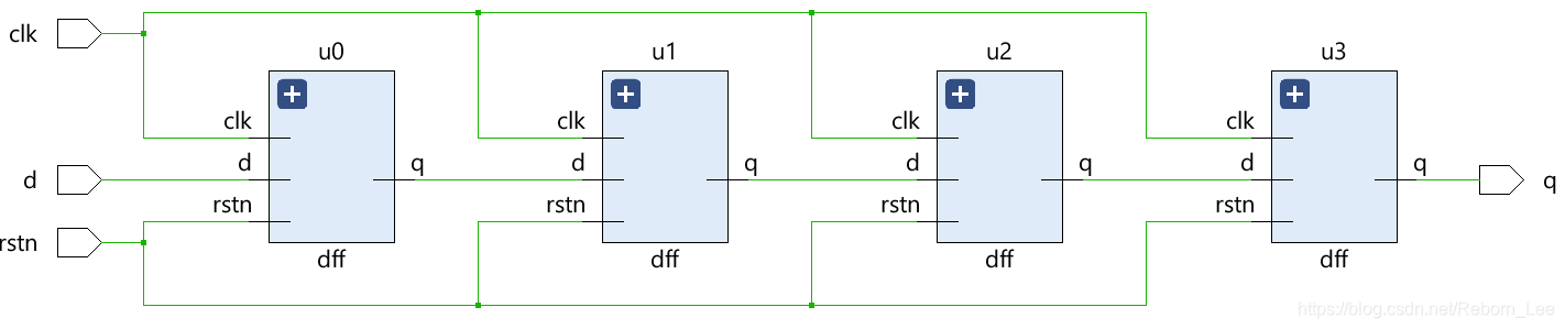
通过例化触发器形成移位寄存器,移位寄存器如果端口都连接了:
module shift_reg (   input   d,
                    input    clk,
                    input   rstn,
                    output   q);

  wire [2:0] q_net;
  dff u0 (.d(d),         .clk(clk), .rstn(rstn), .q(q_net[0]));
  dff u1 (.d(q_net[0]), .clk(clk), .rstn(rstn), .q(q_net[1]));
  dff u2 (.d(q_net[1]), .clk(clk), .rstn(rstn), .q(q_net[2]));
  dff u3 (.d(q_net[2]), .clk(clk), .rstn(rstn), .q(q));

endmodule
RTL原理图:
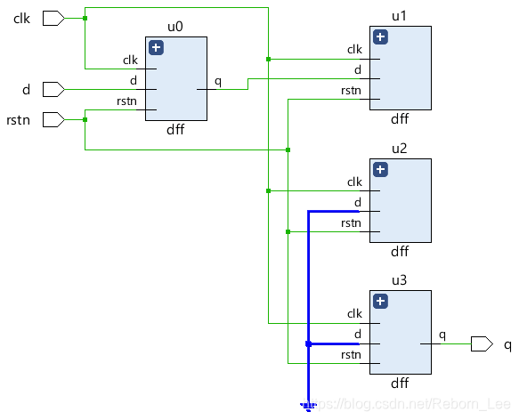
如果有一些端口未连接:
module shift_reg (   input   d,
                    input    clk,
                    input   rstn,
                    output   q);

  wire [2:0] q_net;

  dff u0 (.d(d),         .clk(clk), .rstn(rstn), .q(q_net[0]));
  dff u1 (.d(q_net[0]), .clk(clk), .rstn(rstn), .q());             // Output q is left floating
  dff u2 (.d(q_net[1]), .clk(clk), .rstn(rstn), .q());             // Output q is left floating
  dff u3 (.d(q_net[2]), .clk(clk), .rstn(rstn), .q(q));

endmodule
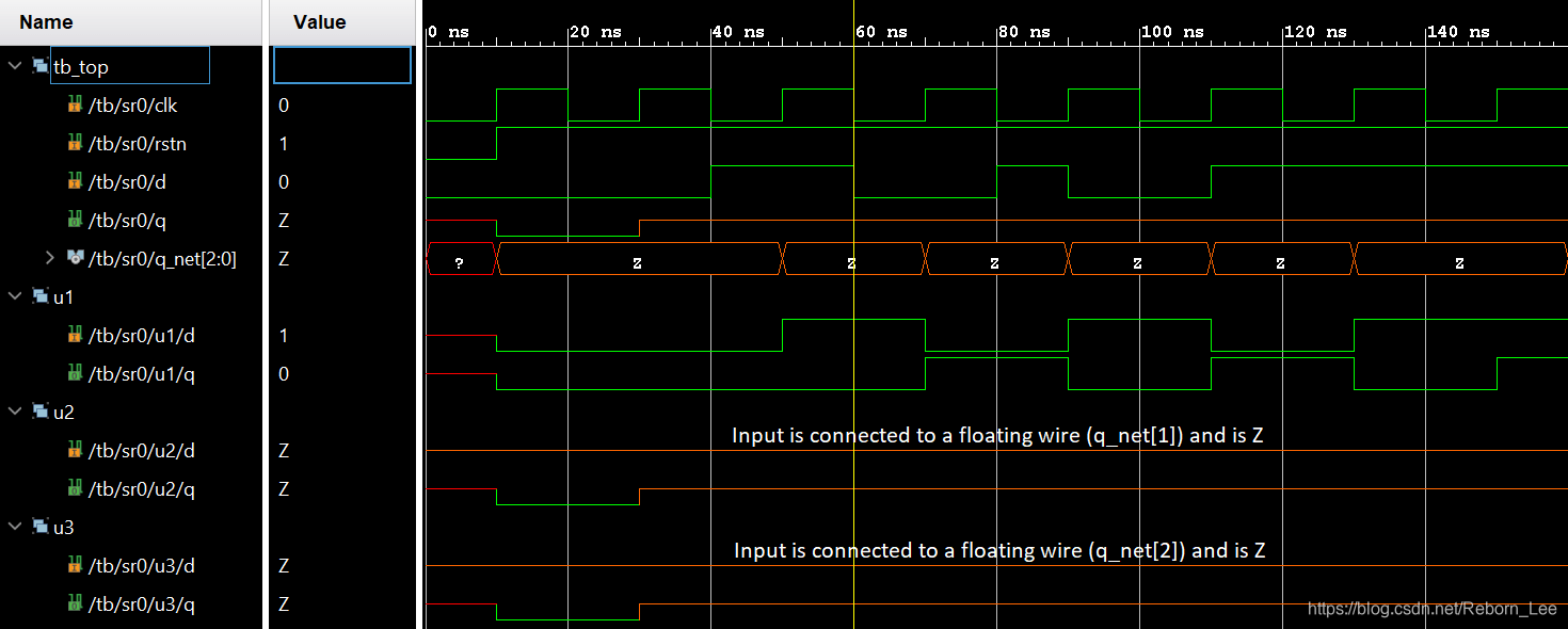
RTL原理图为:
在仿真中,由于端口悬空了,所以,输出也是高阻态z。
关于模块端口的说明
所有的端口声明都隐含地声明为wire,因此在这种情况下端口方向就足够了。然而需要存储值的输出端口应该声明为 reg 数据类型,并且可以在程序块中使用,比如 always 和 initial only。
输入或inout类型的端口不能声明为reg,因为它们是由外部连续驱动的,不应该存储值,而是尽快反映外部信号的变化。连接两个不同向量大小的端口是完全合法的,但以向量大小较小的端口为准,而另一个宽度较大的端口的剩余位将被忽略。
参考资料
交个朋友
-
个人微信公众号:FPGA LAB
-
知乎:李锐博恩