雾的计算原理其实很简单
float3 finalColor = f * fogColor + (1-f)originColor
也就是按照某种比例把雾的纹理和原始的纹理相融合,其中比较关键的点就是f的选取
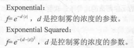
f的选取有多种方式,比如说f=dmax-d/dmax-dmin 这种的就是线性的雾,直观的感觉就是高度越接近dmin,雾的浓度越大,越接近dmax,雾的浓度就越小,此外,还有指数形式的计算方法,公式如下所示,实现的时候只需要把d作为输入参数,然后替换一下shader里面的公式即可。
我们观察线性雾的公式,其中d是我们不知道的,也就是世界坐标的高度值,这就意味着我们想要实现全局雾效的效果就必须要获得世界坐标,获得世界坐标的办法在运动模糊里面通过世界投影矩阵矩阵已经实现过了,但是之前的那种办法需要在shader里面进行两次矩阵的乘法运算,很影响算法的效率,在这里,我们使用另外一种方法来获取世界坐标。
我们将摄像机与屏幕上某一点连线,获得一个方向向量,然后把这个方向向量深度值+摄像机的位置就是世界坐标了,直观上也很容易理解。
float4 worldPos = _WorldSpaceCameraPos + linearDepth * interpolatedRay;
上面公式中,只有interpolatedRay是未知的,这里我们简单的推导一下interpolatedRay是怎么来的。
interpolatedRay来自于对近裁剪面四个顶点与摄像机形成的方向向量的差值。首先我们需要获得摄像机和近裁剪面的四个顶点的连线向量。
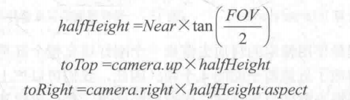
halfHeight是近裁剪面高度的一半,toTop则是方向朝上,大小为halfHeight的向量,toRight则是方向朝右,大小为近裁剪面宽度一半的向量。

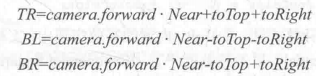
上面则是我们需要的四个方向向量的值,理解起来也很容易,就是单纯的向量加减运算。
此外,还需要注意一点,深度纹理获得的深度值是z的值,而不是沿着这四个方向的深度值,我们需要的深度值是下面?的那个值,那才是真正的深度。
 由相似三角形也能推导出来
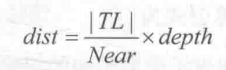
我们把
提取出来,做一个常量,乘以归一化的上面的四个向量,然后就可以通过float4 worldPos = _WorldSpaceCameraPos + linearDepth * interpolatedRay;来求得最后的世界坐标了。
首先我们来看一下脚本部分:
脚本中最重要的内容就是计算出来上面提到的四个向量,而计算过程也是中规中矩,按照我们的公式来的。如果上面的公式弄懂了的话,代码也是水到渠成的。
Matrix4x4 frustumCorners = Matrix4x4.identity;

float fov = camera.fieldOfView;
float near = camera.nearClipPlane;
float aspect = camera.aspect;

float halfHeight = near * Mathf.Tan(fov * 0.5f * Mathf.Deg2Rad);
Vector3 toRight = cameraTransform.right * halfHeight * aspect;
Vector3 toTop = cameraTransform.up * halfHeight;

Vector3 topLeft = cameraTransform.forward * near + toTop - toRight;
float scale = topLeft.magnitude / near;

topLeft.Normalize();
topLeft *= scale;

Vector3 topRight = cameraTransform.forward * near + toRight + toTop;
topRight.Normalize();
topRight *= scale;

Vector3 bottomLeft = cameraTransform.forward * near - toTop - toRight;
bottomLeft.Normalize();
bottomLeft *= scale;

Vector3 bottomRight = cameraTransform.forward * near + toRight - toTop;
bottomRight.Normalize();
bottomRight *= scale;
frustumCorners.SetRow(0, bottomLeft);
frustumCorners.SetRow(1, bottomRight);
frustumCorners.SetRow(2, topRight);
frustumCorners.SetRow(3, topLeft);

material.SetMatrix("_FrustumCornersRay", frustumCorners);
后面就是shader部分了,基本上的思路还是很清晰的,顶点着色器的内容就是判断出屏幕上的点离近裁剪面四个顶点最近的是哪个向量,然后返回那个向量。中间很长一段的代码都是在做平台差异化处理。
片元着色器是整个算法的核心,首先根据前面所讨论出来的算法计算出来世界坐标,虽然顶点着色器传过去的只是一个给定的边缘向量,但是在片元着色器中会进行差值,具体是怎么差值的我们后面再讨论。
然后就是采样噪声图,并通过_Time.y来动态改变采样的坐标,实现动画效果,再后面就是我们之前提到的线性的雾计算公式中的f的计算,计算出来的f还会根据采样的噪声图进行偏移,得到更加真实的效果,最后再把雾和原图进行混合即可。
shader源码:
Shader "Unity Shaders Book/Chapter 15/Fog With Noise" {
	Properties {
		_MainTex ("Base (RGB)", 2D) = "white" {}
		_FogDensity ("Fog Density", Float) = 1.0
		_FogColor ("Fog Color", Color) = (1, 1, 1, 1)
		_FogStart ("Fog Start", Float) = 0.0
		_FogEnd ("Fog End", Float) = 1.0
		_NoiseTex ("Noise Texture", 2D) = "white" {}
		_FogXSpeed ("Fog Horizontal Speed", Float) = 0.1
		_FogYSpeed ("Fog Vertical Speed", Float) = 0.1
		_NoiseAmount ("Noise Amount", Float) = 1
	}
	SubShader {
		CGINCLUDE

		#include "UnityCG.cginc"

		float4x4 _FrustumCornersRay;

		sampler2D _MainTex;
		half4 _MainTex_TexelSize;
		sampler2D _CameraDepthTexture;
		half _FogDensity;
		fixed4 _FogColor;
		float _FogStart;
		float _FogEnd;
		sampler2D _NoiseTex;
		half _FogXSpeed;
		half _FogYSpeed;
		half _NoiseAmount;

		struct v2f {
			float4 pos : SV_POSITION;
			float2 uv : TEXCOORD0;
			float2 uv_depth : TEXCOORD1;
			float4 interpolatedRay : TEXCOORD2;
		};

		v2f vert(appdata_img v) {
			v2f o;
			o.pos = UnityObjectToClipPos(v.vertex);

			o.uv = v.texcoord;
			o.uv_depth = v.texcoord;

			#if UNITY_UV_STARTS_AT_TOP
			if (_MainTex_TexelSize.y < 0)
				o.uv_depth.y = 1 - o.uv_depth.y;
			#endif

			int index = 0;
			if (v.texcoord.x < 0.5 && v.texcoord.y < 0.5) {
				index = 0;
			} else if (v.texcoord.x > 0.5 && v.texcoord.y < 0.5) {
				index = 1;
			} else if (v.texcoord.x > 0.5 && v.texcoord.y > 0.5) {
				index = 2;
			} else {
				index = 3;
			}
			#if UNITY_UV_STARTS_AT_TOP
			if (_MainTex_TexelSize.y < 0)
				index = 3 - index;
			#endif

			o.interpolatedRay = _FrustumCornersRay[index];

			return o;
		}

		fixed4 frag(v2f i) : SV_Target {

			float linearDepth = LinearEyeDepth(SAMPLE_DEPTH_TEXTURE(_CameraDepthTexture, i.uv_depth));
			float3 worldPos = _WorldSpaceCameraPos + linearDepth * i.interpolatedRay.xyz;

			float2 speed = _Time.y * float2(_FogXSpeed, _FogYSpeed);
			float noise = (tex2D(_NoiseTex, i.uv + speed).r - 0.5) * _NoiseAmount;

			float fogDensity = (_FogEnd - worldPos.y) / (_FogEnd - _FogStart);
			fogDensity = saturate(fogDensity * _FogDensity * (1 + noise));

			fixed4 finalColor = tex2D(_MainTex, i.uv);
			finalColor.rgb = lerp(finalColor.rgb, _FogColor.rgb, fogDensity);

			return finalColor;
		}

		ENDCG

		Pass {
			CGPROGRAM

			#pragma vertex vert
			#pragma fragment frag

			ENDCG
		}
	}
	FallBack Off
}
对比图如下:

 不过,其中我还是有一处疑问的,那就是传递到v2f的坐标是如何差值到片元着色器的,为此,我进行了一个小实验,首先把四个向量的顶点坐标映射到(0,1),这样做是为了方便的把其作为颜色显示出来。然后输出这四个向量以及差值后的向量
//tst
bottomLeft.x = (bottomLeft.x + 1.1f) / 2.2f;
bottomLeft.y = (bottomLeft.y + 1) / 2;
bottomLeft.z = (bottomLeft.z - 0.6f) / 0.6f;
bottomRight.x = (bottomRight.x + 1.1f) / 2.2f;
bottomRight.y = (bottomRight.y + 1) / 2;
bottomRight.z = (bottomRight.z - 0.6f) / 0.6f;
topLeft.x = (topLeft.x + 1.1f) / 2.2f;
topLeft.y = (topLeft.y + 1) / 2;
topLeft.z = (topLeft.z - 0.6f) / 0.6f;
topRight.x = (topRight.x + 1.1f) / 2.2f;
topRight.y = (topRight.y + 1) / 2;
topRight.z = (topRight.z - 0.6f) / 0.6f;
//
然后我们改写片元着色器,直接输出四个向量值


 最后再输出interpolatedRay的值,可以很清楚的看到,它确实是经过线性差值了,至于怎么差值的,那是硬件做的事情了,不做过多的讨论。

