前言
MPC5748G开发环境搭建
MPC5748G S32_SDK_PA_RTM_3.0.0 GPIO 调试仿真设置
前两篇讲了开发环境的搭建, GPIO的读写操作, 调试仿真的设置等, 本篇介绍下定时器的使用.
定时器简介
MPC5748G的定时器种类有点多:
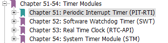
其中, 一个PIT和3个STM类似于我们传统意义上的定时器.
PIT有16通道, 每通道有32位长, 连续通道可以软件链成64位定时器:


3个STM的介绍:

PIT和STM都可以用SDK中的timing_pal来操作. 这里以PIT为例.
新建工程
仍以DEVKIT-MPC5748G为例, 使用定时器翻转LED(PTJ4). 新建工程步骤如下:
- 打开S32, File -> New -> S32DS Application Project
- 选择MCU: MPC5748G, 填入工程名
- 默认3个核都勾上了, 这里去掉Z4_1和Z2_2的勾选, 只保留Z4_0, 选择SDK: MPC5748G_SDK_Z4_0 3.0.0, 点击Finish结束:

PE配置
先把PJ4的LED搞上去:

Components Library中双击添加timing_pal:

点击左侧timing_pal1:timing_pal进行配置:

Channel可选0~15通道, 类型可选连续(Continuous)或者单次(One-shot), 通道的回调函数名字自己写.
点击生成代码:

补全代码
/* User includes (#include below this line is not maintained by Processor Expert) */

#define LED_PORT        PTJ
#define LED_PIN         4U

#define PIT_CHANNEL	    0UL
#define PERIOD_BY_NS	1000000000UL /* nanosecond unit, The period is 1 second */

void pit_0_callback(void * userData) {
	(void)userData;
	PINS_DRV_TogglePins(LED_PORT, (1 << LED_PIN));
}

/*!
  \brief The main function for the project.
  \details The startup initialization sequence is the following:
 * - startup asm routine
 * - main()
*/
int main(void)
{
  /* Write your local variable definition here */
	uint64_t pitResolution;

  /*** Processor Expert internal initialization. DON'T REMOVE THIS CODE!!! ***/
  #ifdef PEX_RTOS_INIT
    PEX_RTOS_INIT();                   /* Initialization of the selected RTOS. Macro is defined by the RTOS component. */
  #endif
  /*** End of Processor Expert internal initialization.                    ***/

  /* Write your code here */
  /* For example: for(;;) { } */
    /* Initialize clock gate*/
    CLOCK_SYS_Init(g_clockManConfigsArr,   CLOCK_MANAGER_CONFIG_CNT,
    	           g_clockManCallbacksArr, CLOCK_MANAGER_CALLBACK_CNT);
    CLOCK_SYS_UpdateConfiguration(0U, CLOCK_MANAGER_POLICY_AGREEMENT);

    /* Initialize and configure pins */
    PINS_DRV_Init(NUM_OF_CONFIGURED_PINS, g_pin_mux_InitConfigArr);

    PINS_DRV_SetPins(LED_PORT, (1 << LED_PIN));

    /* Initialize TIMING over PIT */
    TIMING_Init(&timing_pal1_instance, &timing_pal1_InitConfig);

	/* Get tick resolution in nanosecond unit for TIMING over PIT */
	TIMING_GetResolution(&timing_pal1_instance, TIMER_RESOLUTION_TYPE_NANOSECOND, &pitResolution);

	/* Start PIT channel 0 counting with the period is 1 second,
       the period in tick = the period in nanosecond / PIT tick resolution in nanosecond */
	TIMING_StartChannel(&timing_pal1_instance, PIT_CHANNEL, PERIOD_BY_NS/pitResolution);

	while(1);

  /*** Don't write any code pass this line, or it will be deleted during code generation. ***/
  /*** RTOS startup code. Macro PEX_RTOS_START is defined by the RTOS component. DON'T MODIFY THIS CODE!!! ***/
  #ifdef PEX_RTOS_START
    PEX_RTOS_START();                  /* Startup of the selected RTOS. Macro is defined by the RTOS component. */
  #endif
  /*** End of RTOS startup code.  ***/
  /*** Processor Expert end of main routine. DON'T MODIFY THIS CODE!!! ***/
  for(;;) {
    if(exit_code != 0) {
      break;
    }
  }
  return exit_code;
  /*** Processor Expert end of main routine. DON'T WRITE CODE BELOW!!! ***/
} /*** End of main routine. DO NOT MODIFY THIS TEXT!!! ***/

/* END main */
这里调试没有运行起来, 下载进去拔掉OpenSDA的USB可以运行, 还不晓得哪里出了什么差错.
微信公众号
欢迎扫描关注我的微信公众号, 及时获取最新文章: