Theoretical basics of SPI
The SPI • (Serial Peripheral Interface):
• Serial Peripheral Interface, is a Motorola has introduced a synchronous serial interface technology, is a high-speed, full-duplex, synchronous communication bus.
• SPI mainly four-wire:
• the SS (the Select the Slave): the enable signal from the device, is controlled by the master device. ;
• the SCK (Serial Clock): a clock signal line, issued by the master device;
• the MOSI (Master the Output the Slave the Input): Master Out / Slave device input pin;
• the MISO (Master the Slave the Output the Input): Master Input / from the device output pins.
SPI advantages and disadvantages
1, the advantages of the SPI
1) supporting full duplex communication
2) simple communication
3) faster data transfer rate
2, disadvantages
1) flow control is not assigned, no acknowledgment to confirm whether the received data
2) has some shortcomings reliability.
3, the characteristics of
1) high-speed, synchronous, full-duplex, non-differential, Bus
2) master-slave communication mode
SPI mode of communication
• a communication mode, as follows:
• Mode0: the CPOL = 0, CPHA = 0
• Mode1: the CPOL = 0, CPHA =. 1
• Mode2: the CPOL =. 1, CPHA = 0
• Mode3: the CPOL =. 1, CPHA =. 1
• clock electrode CPOL of electricity is used to configure SCLK which is the idle state when the state or level for effective state, the clock phase CPHA
• configuration data is used in the first few samples are edge:
• CPOL = 0, indicates when SCLK = 0 while in the idle state, the active state when the SCLK is at a high level
• CPOL = 1, indicates when the idle state when the SCLK = 1, the active state when the SCLK is at a low level
• CPHA = 0, the data samples are represented in the first a rim, data transmitted during the second edge
• CPHA = 1, denotes sampling data at the second edge, the first data transmitted in an edge
Find LCD development board
FIG, 6 is a development of the LCD panel with a resolution of 240 * 240
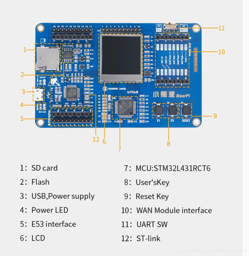
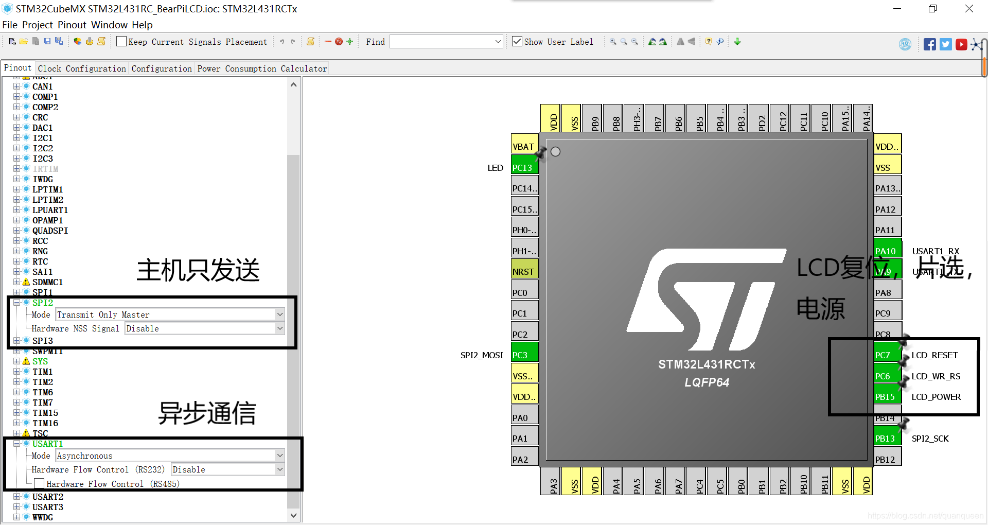
LCD pin
1) PC3 is SPI2_MOSI master out / slave pin;
2) as PB13 is SPI2_SCK clock pin;
. 3) of the PC6 LCD_WR_RS chip select pin;
. 4) is LCD_RESET reset pin PC7;
. 5) is LCD_POWER PB15 power supply pin;
6) PA9 UART1 is transmitting pin;
. 7) is UART1 receive pin P10;
. 8) PC 13 is an LED pin.
After drawing can find LCD pin according to the principle, to find pins, configuration pins on STM32CubeMX
Pin Configuration
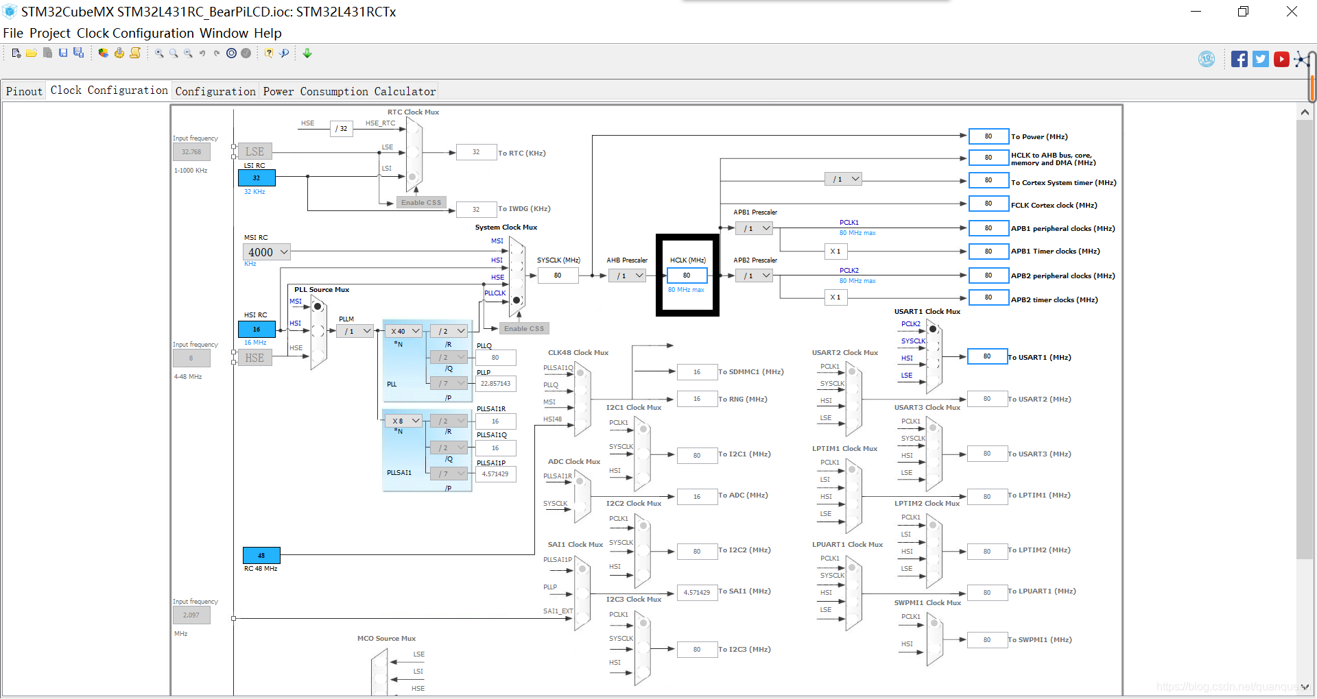
Configure the system clock
Using the internal clock (default) the system clock up to 80MHZ
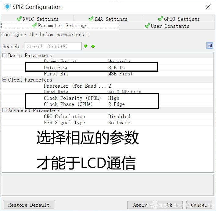
LCD configuration parameters
LCD production project
1, custom project name.
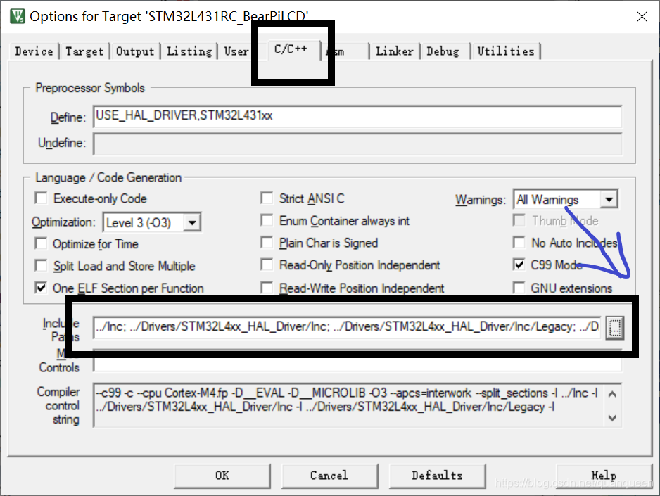
2. Select English path, otherwise it will lose boot files can not be compiled by the need to manually add the startup file: startup_stm32l431xx.s
3, select MDK-ARM V5 development software, namely KEIL5 software.
Code written instructions
1, initialization parameters SPI hardware and communication protocols.
2, SPI one-way only, i.e. only uses three pins, i.e., the master out / slave clock, chip select;
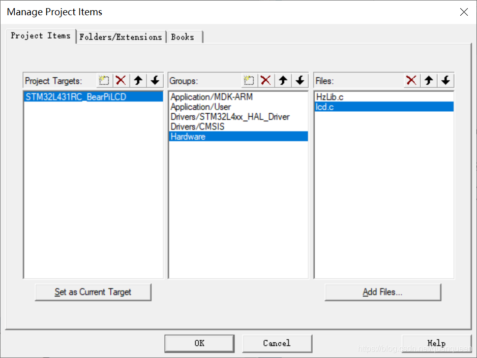
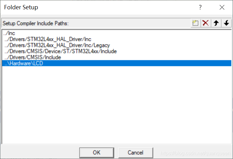
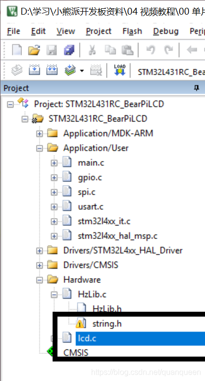
3, and transplant LCD driver interface function;
4, an LCD display interface functions English strings ( also can display characters);
5, a string of different font sizes interface function using the LCD display;
6, an LCD interface function circle.
Call functions :
. 1, HAL_SPI_Transmit (SPI_HandleTypeDef * HSPI, uint8_t pData, uint16_t Size, the Timeout uint32_t);
2, HAL_GPIO_WritePin (GPIO_TypeDef the GPIOx, uint16_t GPIO_Pin); // main function of lighting the LED
. 3, void HAL_Delay (uint32_t Delay); Yan when the function
LCD driver interface functions and transplantation
Coding to achieve
LCD_Init();//初始化LCD,该函数中调用的硬件初始化已经屏蔽吊,本教程使用的是CubeMX生成的硬件初始化
while (1)
{
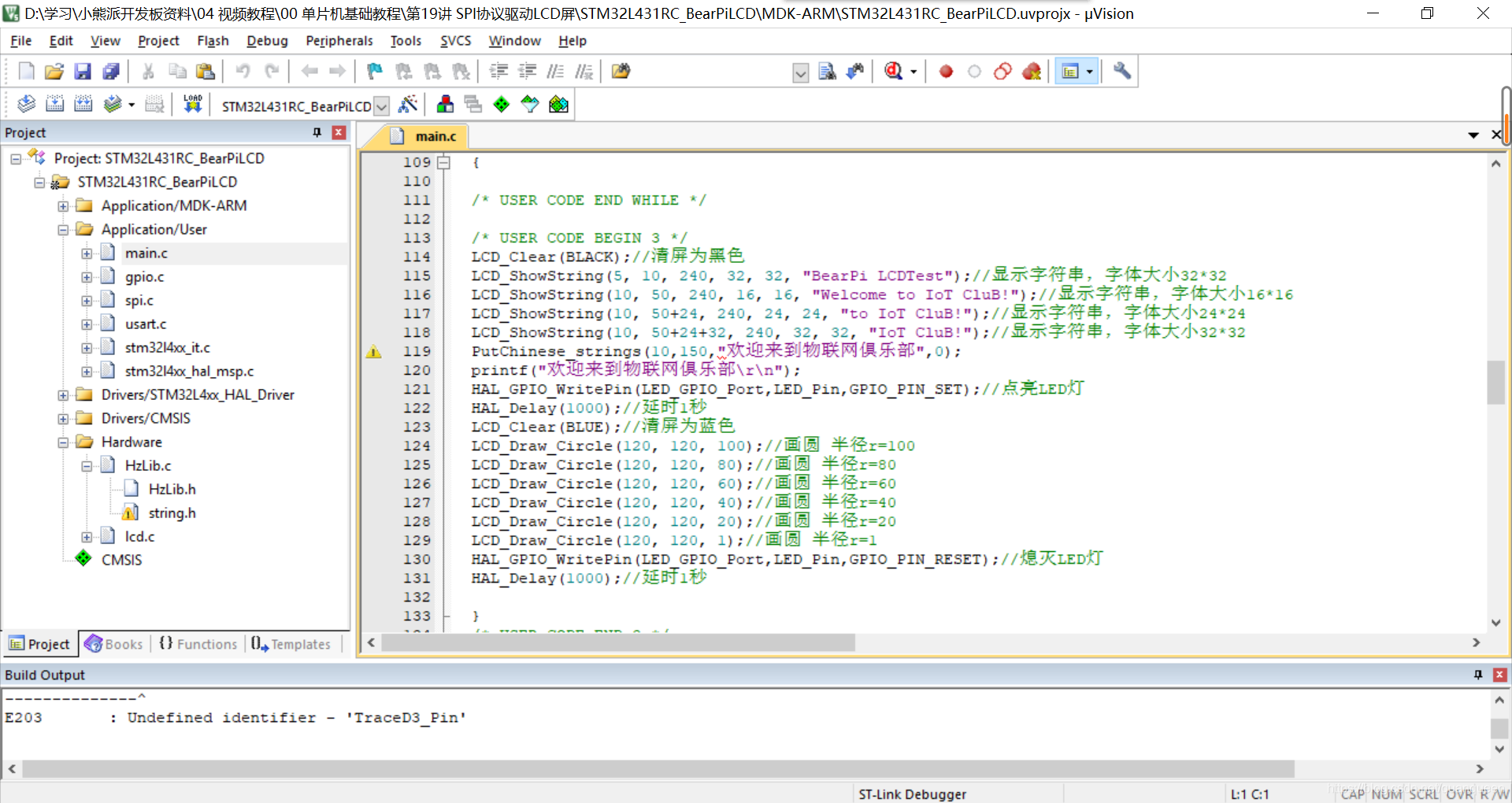
LCD_Clear(BLACK);//清屏为黑色
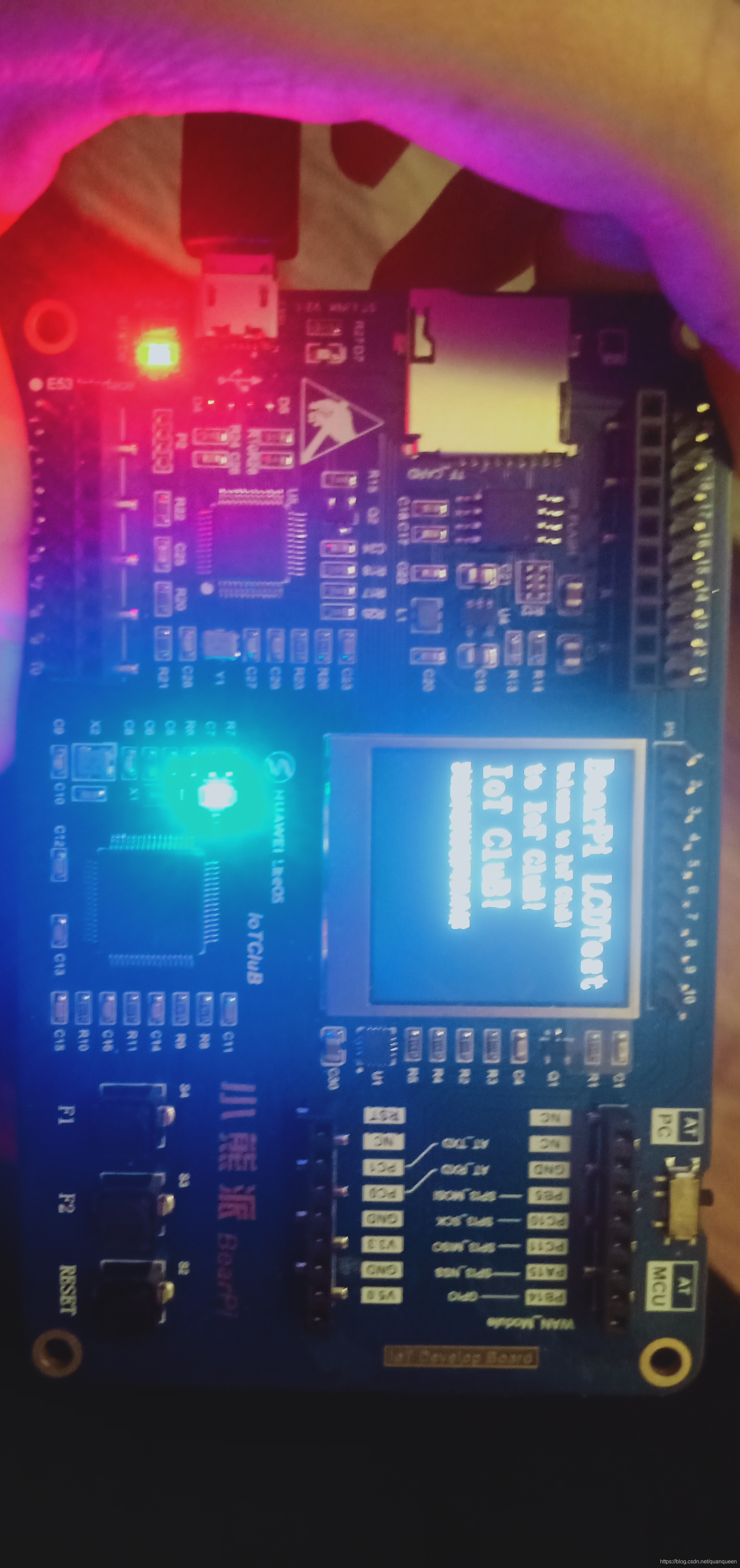
LCD_ShowString(5, 10, 240, 32, 32, "BearPi LCDTest");//显示字符串,字体大小32*32 LCD_ShowString(10, 50, 240, 16, 16, "Welcome to IoT CluB!");//显示字符串,字体大小16*16
LCD_ShowString(10, 50+24, 240, 24, 24, "to IoT CluB!");//显示字符串,字体大小24*24 LCD_ShowString(10, 50+24+32, 240, 32, 32, "IoT CluB!");//显示字符串,字体大小32*32
HAL_GPIO_WritePin(LED_GPIO_Port,LED_Pin,GPIO_PIN_SET);//点亮LED灯 HAL_Delay(1000);//延时1秒 LCD_Clear(BLUE);//清屏为蓝色
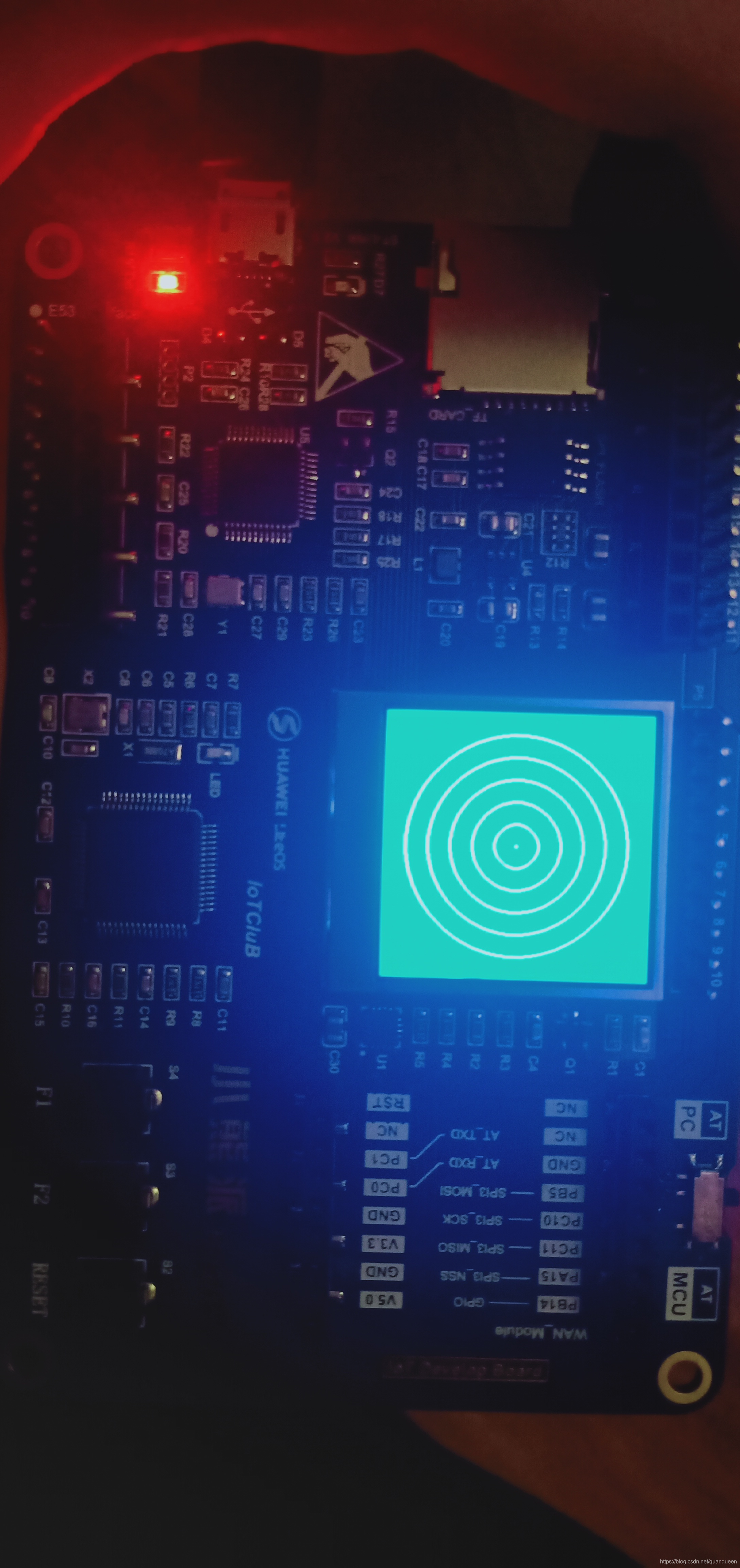
LCD_Draw_Circle(120, 120, 100);//画圆 半径r=100
LCD_Draw_Circle(120, 120, 80);//画圆 半径r=80
LCD_Draw_Circle(120, 120, 60);//画圆 半径r=60
LCD_Draw_Circle(120, 120, 40);//画圆 半径r=40
LCD_Draw_Circle(120, 120, 20);//画圆 半径r=20
LCD_Draw_Circle(120, 120, 1);//画圆 半径r=1 HAL_GPIO_WritePin(LED_GPIO_Port,LED_Pin,GPIO_PIN_RESET);//熄灭LED灯 HAL_Delay(1000);//延时1秒
}
Show results
Experimental phenomena