State Machine - Overlapping Sequence Detection
`timescale 1ns/1ns

module sequence_test2(
	input wire clk  ,
	input wire rst  ,
	input wire data ,
	output reg flag
);
//*************code***********//
    parameter S0=0, S1=1, S2=2, S3=3, S4=4;
    reg [2:0] state, nstate;

    always@(posedge clk or negedge rst) begin
        if(~rst)
            state <= S0;
        else
            state <= nstate;
    end

    always@(*) begin
        if(~rst)
            nstate <= S0;
        else
            case(state)
                S0     : nstate <= data? S1: S0;
                S1     : nstate <= data? S1: S2;
                S2     : nstate <= data? S3: S0;
                S3     : nstate <= data? S4: S2;
                S4     : nstate <= data? S1: S2;
                default: nstate <= S0;
            endcase
    end

    always@(posedge clk or negedge rst) begin
        if(~rst)
            flag <= 0;
        else
            flag <= state==S4;
    end

//*************code***********//
endmodule
State machine - non-overlapping sequence detection
Only detect a sequence once. This is the real thing. You don’t need to consider other things. Just match. Don’t worry about mismatching.
`timescale 1ns/1ns

module sequence_test1(
	input wire clk  ,
	input wire rst  ,
	input wire data ,
	output reg flag
);
parameter idle=0,s1=1,s2=2,s3=3,s4=4,s5=5;
reg[2:0]cs;
reg[2:0]ns;
always@(posedge clk,negedge rst)begin
	if(!rst)begin
		cs<=idle;
	end
	else begin
		cs<=ns;
	end
end
always@(*)begin
	case(cs)
	idle:ns=(data==1)?s1:idle;
	s1:ns=(data==0)?s2:idle;
	s2:ns=(data==1)?s3:idle;
	s3:ns=(data==1)?s4:idle;
	s4:ns=(data==1)?s5:idle;
	default:ns=idle;
	endcase
end
always@(posedge clk,negedge rst)begin
	if(!rst)begin
		flag<=0;
	end
	else begin
		flag<=ns==s5;
	end
end
endmodule
Non-overlapping sequence detection
state machine
It is more convenient to use a state machine. For sequence detection, the method is selected according to the characteristics. The simplest is the MOORE type. It depends on whether it is slow or not. Change CS and NS directly during the output judgment. If you want it to be slower, use CS. If not, use CS. Just NS
The MOORE and MEALY types of nS are the same synchronization
If there is no overlap, it will directly return to the initial state when there is no match, and there is no need for Kmp matching.
Shift Register
On the basis of the shift register, a CNT limit is added'
`timescale 1ns/1ns
module sequence_detect(
	input clk,
	input rst_n,
	input data,
	output reg match,
	output reg not_match
	);
    reg[2:0]cnt;
    reg[5:0]ram;
    always@(posedge clk,negedge rst_n)begin
        if(!rst_n)
            cnt<=0;
        else
            cnt<=cnt==5?0:cnt+1;
    end
    always@(posedge clk,negedge rst_n)begin
        if(!rst_n)
            ram<=0;
        else
            ram<={ram[4:0],data};
    end
    always@(posedge clk,negedge rst_n)begin
        if(!rst_n)begin
            match<=0;
            not_match<=0;
        end
        else begin
            match<=(cnt==5)&&({ram[4:0],data}==6'b011100);
            not_match<=(cnt==5)&&({ram[4:0],data}!=6'b011100);
        end
    end
endmodule
Sequence detection with extraneous items
Shift Register
Use two signals to determine whether the left and right sides meet the requirements. If both are met, output 1
`timescale 1ns/1ns
module sequence_detect(
	input clk,
	input rst_n,
	input a,
	output match
	);
reg[8:0]temp;
always@(posedge clk,negedge rst_n)begin
	if(!rst_n)begin
		temp<=9'b0;
	end
	else begin
		temp<={temp[7:0],a};
	end
end

reg ma;
reg mb;
always@(posedge clk,negedge rst_n)begin
	if(!rst_n)begin
		ma<='b0;
	end
	else begin
		if(temp[8:6]==3'b011)
			ma<=1'b1;
		else
			ma<=1'b0;
	end
end
always@(posedge clk,negedge rst_n)begin
	if(!rst_n)begin
		mb<='b0;
	end
	else begin
		if(temp[2:0]==3'b110)
			mb<=1'b1;
		else
			mb<=1'b0;
	end
end
assign match=ma&mb;
endmodule
Sequence detection for continuous input sequence
Shift Register
This shift register directly determines what is stored in the register, that is, the current state of the register, so it is a MOORE state machine.
`timescale 1ns/1ns
module sequence_detect(
	input clk,
	input rst_n,
	input a,
	output reg match
	);
reg[7:0]atemp;
always@(posedge clk,negedge rst_n)begin
	if(!rst_n)begin
		atemp<=8'b0;
	end
	else
		atemp<={atemp[6:0],a};
end
always@(posedge clk,negedge rst_n)begin
	if(!rst_n)begin
		match=1'b0;
	end
	else begin
		if(atemp==8'b0111_0001)
		match=1'b1;
		else
		match='b0;
	end
end

endmodule
state machine
`timescale 1ns/1ns
module sequence_detect(
	input clk,
	input rst_n,
	input a,
	output reg match
	);
parameter idle=0,s1=1,s2=2,s3=3,s4=4,s5=5,s6=6,s7=7,s8=8;
reg[3:0]cs;
reg[3:0]ns;
always@(posedge clk,negedge rst_n)begin
	if(!rst_n)
		cs<=idle;
	else
		cs<=ns;
end
always@(*)begin
	case(cs)
	idle:begin
		ns=(a==0)?s1:idle;
	end
	s1:begin
		ns=(a==1)?s2:s1;
	end
	s2:begin
		ns=(a==1)?s3:s1;
	end
	s3:begin
		ns=(a==1)?s4:s1;
	end
	s4:begin
		ns=(a==0)?s5:idle;
	end
	s5:begin
		ns=(a==0)?s6:s2;
	end
	s6:begin
		ns=(a==0)?s7:s2;
	end
	s7:begin
		ns=(a==1)?s8:s1;
	end
	s8:begin
		ns=(a==1)?s3:s1;
	end
	default:ns=idle;
	endcase
end
always@(posedge clk,negedge rst_n)begin
	if(!rst_n)
		match<=0;
	else
		match<=(cs==s8)?1:0;
end
endmodule
What the MOORE machine judges is the current state, so take a slow shot.
When the MOORE machine determines the next state, it is output synchronously like the MEALY machine.
Sequence detection for input sequence discontinuities
Shift register (output in the same cycle, MEALY type)
In the output judgment, it is determined by the current state and the input signal.
It is to shift when it is valid, and then also note that since the signal is to be output in the same beat, since the shift is updated in the next bit, the ram updated in this cycle will be carried out in the next cycle. Judgment, so it will lead to delay, so the output judgment must be combined with the current status, that is, MEALY type
`timescale 1ns/1ns
module sequence_detect(
	input clk,
	input rst_n,
	input data,
	input data_valid,
	output reg match
	);
reg[3:0]ram;
always@(posedge clk,negedge rst_n)begin
	if(!rst_n)begin
		ram=4'b0;
	end
	else if(data_valid)begin
		ram<={ram[2:0],data};
	end
	else begin
		ram<=ram;
	end
end
always@(posedge clk,negedge rst_n)begin
	if(!rst_n)begin
		match<=0;
	end
	else begin
		match<=(ram[2:0]==3'b011)&&data&&data_valid;
	end
end
endmodule
State machine (MOORE type)
The MOORE type is only related to the current state, so when outputting judgment, ns== is used, that is, what the secondary state is equal to.
And if it is MEALY, it is the current state plus input
`timescale 1ns/1ns
module sequence_detect(
	input clk,
	input rst_n,
	input data,
	input data_valid,
	output reg match
	);
	parameter idle=0,s0=1,s1=2,s2=3,s3=4;
	reg[2:0]cs;
	reg[2:0]ns;
	always@(posedge clk,negedge rst_n)begin
		if(!rst_n)begin
			cs<=idle;
		end
		else begin
			cs<=ns;
		end
	end
	always@(*)begin
		case(cs)
		idle:begin
			if(data_valid)
				ns=(data==1)?idle:s0;
			else
				ns=idle;
		end
		s0:begin
			if(data_valid)
				ns=(data==1)?s1:s0;
			else
				ns=s0;
		end
		s1:begin
			if(data_valid)
				ns=(data==1)?s2:s0;
			else
				ns=s1;
		end
		s2:begin
			if(data_valid)
				ns=(data==0)?s3:idle;
			else
				ns=s2;
		end
		s3:begin
			if(data_valid)
				ns=(data==0)?s0:idle;
		end
		endcase
	end
	always@(posedge clk,negedge rst_n)begin
		if(!rst_n)begin
			match<=0;
		end
		else begin
			match<=(ns==s3)?1:0;
		end
	end
endmodule
state machine
It should be noted that the MOORE machine that determines the next state is less than one beat, and the one that actually judges the current state is full of one beat.
The Moore machine has one more state than the Mealy machine. This state represents the initial state.
The output of the Moore machine is determined by the current state, and the output of the Mealy machine is determined by the current state and the input signal.
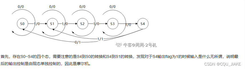
The final output control is controlled solely by the current state, so it is a Moore machine.
Blue represents the output. The Moore machine finally added state S4. From the state transition point of view, the output beat will be one beat later, but because it is a combinational logic output, it is not actually one beat later.
(This means that the MOORE machine and the MEALY machine that judge the next state have the same output, that is, they output in the same cycle, and only the MOORE machine that really judges the current state will be one cycle slower)
The difference between Moore machine and Miller machine : The main difference lies in whether the output of the state machine is related to the current state . The following is a two-stage expression to describe the difference between the two.
It should be noted that if the three-stage description method is used, the difference between the two mainly focuses on whether the judgment in the third stage is based on the current state or the secondary state.
The Moore state machine has one less state than the Miller state machine, and the Moore state machine is one cycle slower; the Miller state machine uses the current input and the current state to jointly judge, while the Moore state machine does not require the current input.
If it is a Moore machine, then in the output, it can only be judged as a secondary state, that is, what the secondary state is;
If you want a meal machine, in the output, it must be judged to be the combination of the current state and the input signal.
This is a Mealy machine, because when outputting, the output signal is controlled by the current state and the input together.
two-stage
The so-called two-stage formula is actually a way of writing specifically for the MOORE machine, because the output of the MOORE machine only depends on the current state, and then it is just a matter of judging the current state, and then judging what the next state is. The output will be one cycle later, and the second-stage The formula is to omit the last section of output and incorporate it into the state transition.
Because it is a MOORE machine, the secondary state is determined in the output. It is better to directly determine the output in the state transition when the secondary state is determined.
three-stage

From the next state to the present state, use posedge,
During state transition, use always@(*)
When exporting, also use posedge
In the first and second processes, since they are all synchronous timing, <= is used in both processes, and = is used in the second process.
`timescale 1ns/1ns


module fsm1(
	input wire clk  ,
	input wire rst  ,
	input wire data ,
	output reg flag
);

    parameter S0 = 'd0, S1 = 'd1, S2 = 'd2, S3 = 'd3 ;
    reg [2:0]	current_state;
    reg [2:0]	next_state;

    always@(posedge clk or negedge rst)begin
        if(rst == 1'b0)begin
            current_state <= S0;
        end
        else begin
            current_state <= next_state;
        end
    end

    always@(*)begin
        case(current_state)
            S0:begin
                next_state = data ? S1 : S0;
            end
            S1:begin
                next_state = data ? S2 : S1;
            end
            S2:begin
                next_state = data ? S3 : S2;
            end
            S3:begin
                next_state = data ? S0 : S3;
            end
            default:begin  next_state = S0; end
        endcase
    end

    always@(posedge clk or negedge rst)begin
        if(rst == 1'b0)begin
            flag <= 1'b0;
        end
        else begin
            if(current_state == S3)begin
				if (data) flag <= 1'b1;
				else flag <= 1'b0;
            end
            else begin
                flag <= 1'b0;
            end
        end
    end

endmodule
This is a meal machine,