The article uses the basic knowledge of UART and the practical application of the serial port screen to illustrate the function of the serial port.
Article directory
foreword
、
1. What is UART?
UART is the abbreviation of Universal Asynchronous Receiver/Transmitter (Universal Asynchronous Receiver/Transmitter), which is a serial communication protocol, usually used to communicate with other devices (such as sensors, modules, displays, etc.) between computers or microprocessors. UART can transmit data from the transmitter to the receiver at a certain rate and format (such as data bits, parity bits, stop bits, etc.), thereby realizing data exchange between the two parties. Common serial communication protocols such as RS-232, RS-485, etc. are all based on UART.
What does asynchronous mean?
Asynchronous communication means that in the communication process, the transmission of data does not depend on the synchronization of the clock signal . In asynchronous communication, data is transmitted in units of characters, and there may be unequal time intervals between each character. The UART protocol is usually used to realize asynchronous communication, in which the sending end and the receiving end communicate through the agreed baud rate, data bits, parity bits, stop bits and other parameters. Compared with synchronous communication, asynchronous communication has the advantages of unlimited transmission rate and low cost, but also has the disadvantages of high transmission error rate.
USART
USART is the abbreviation of Universal Synchronous/Asynchronous Receiver/Transmitter, which includes two modes of asynchronous transmission and synchronous transmission of UART . In asynchronous mode, the USART and UART have the same communication method, and support asynchronous serial data transmission. The data is transmitted in units of characters, and there may be unequal time intervals between each character; Synchronous transmission with the clock signal, the transmission rate of the data and the clock signal is exactly the same, and no stop bit is required. In the application scenario with a high transmission rate, the synchronous mode is more commonly used. USART can support a variety of data formats and transmission rates, and has high communication flexibility and reliability. Parallel and
serial
serial transmission means that data is transmitted bit by bit, and only 1 bit of data can be transmitted at a time., the transmission speed is relatively slow; parallel transmission refers to the simultaneous transmission of multiple data bits, each time multiple binary bits can be transmitted , the transmission speed is faster than serial transmission, but more wires or optical fibers are needed to transmit data.
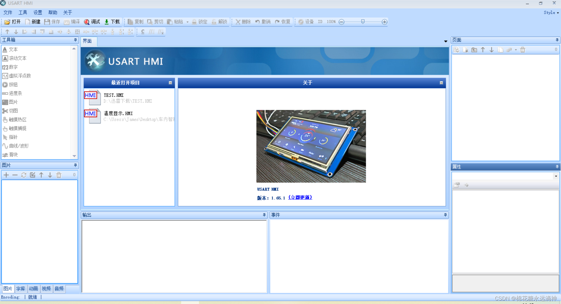
2. USART HMI
The upper computer development software suitable for Tao Jingchi serial port screen can complete the screen content DIY without code.
1. Import font and picture library
Here you can choose to import pictures, fonts, animations, etc. The method of
importing fonts is: click the tool in the upper left corner:
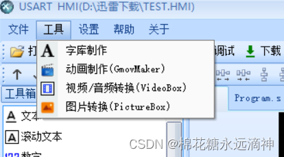
select font creation, and this interface will pop up, you can customize the character height, encoding method and font:
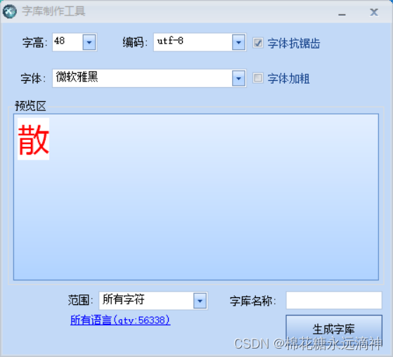
click all languages, only select CJK ideographic characters (The purpose is to reduce the space occupied by characters),
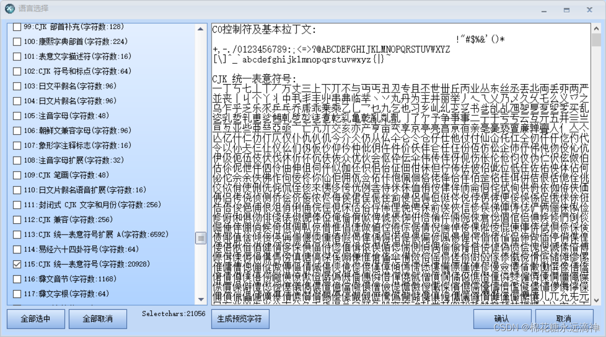
customize the font name, and the saved font will appear in the lower left corner after saving.
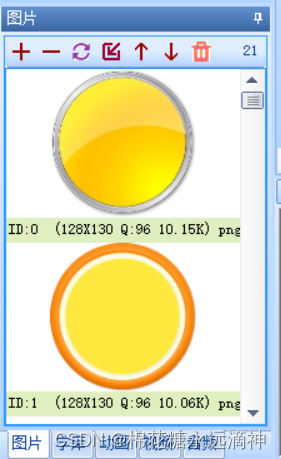
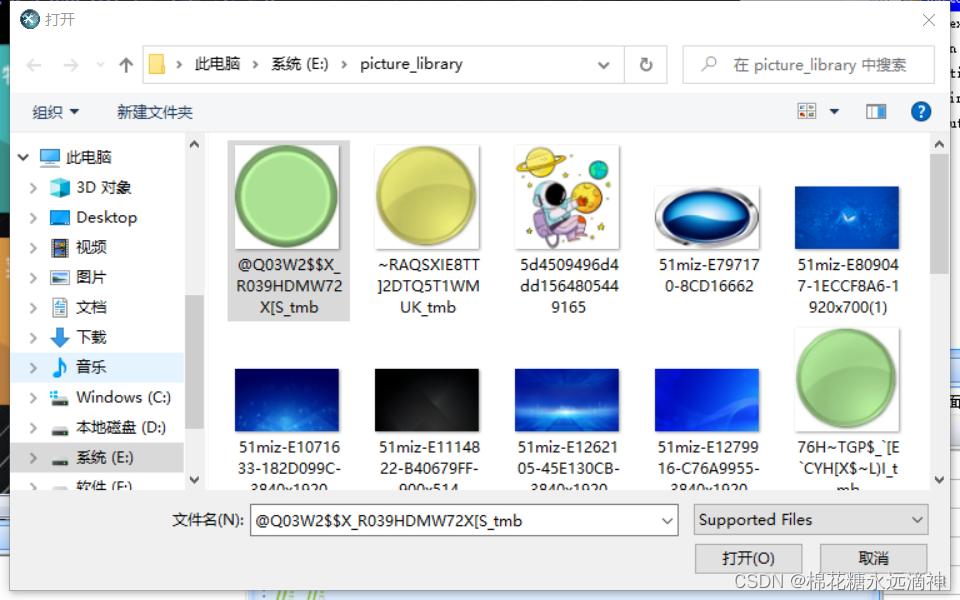
Importing pictures:
relatively simple, just click the plus sign in the lower left corner and add the pictures in your folder.
2. The use of controls and instruction sets
This is the core of the serial screen. Here is an example: the serial port screen setting button sends specific information to STM32, and after STM32 receives it, it controls the LED to turn on and off according to the command.
The first is the HMI part:
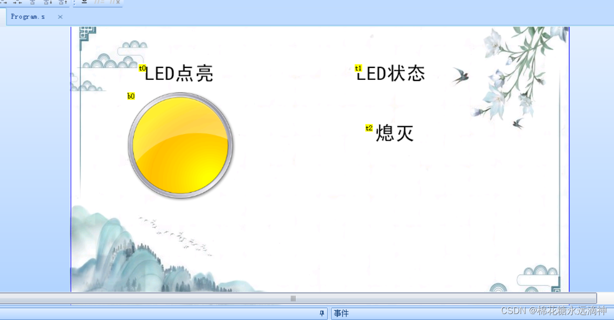
the interface is as shown in the figure, where the b0 control is a button, and the t2 text control, its display (off or on) will change with the status of the LED.
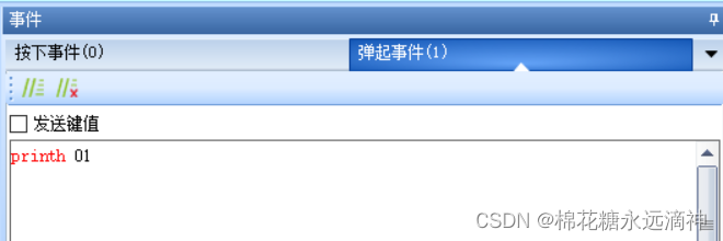
(1) Write the event of the control
Here, write the pop-up event of the LED button: printh 01, that is, after pressing the LED button of the serial port screen and popping up, the hexadecimal data: 0x01 will be sent to the STM32 through the serial port . For the t2 text control, do not write, the change of the t2 control is to receive the string data sent by the STM32 serial port, which is written in stm32.
(2) STM32 serial port programming
Here is a reference to the program of a big guy in CSDN: first, configure the serial port (serial port initialization), use the USART3 of stm32, so the hardware connection should be
RX------------PB10
TX------ ------PB11
first look at the header file:
#ifndef __USART3_H
#define __USART3_H
#include "sys.h"

void HMISendb(u8 k)	;
void HMISends(char *buf1);

void uart3_init(u32 bound);
void USART3_IRQHandler(void);     	//串口1中断服务程序
#endif
Four functions are declared here:
1.uart3_init(u32 bound)
void uart3_init(u32 bound)
{


	//GPIO端口设置
	GPIO_InitTypeDef GPIO_InitStructure;
	USART_InitTypeDef USART_InitStructure;
	NVIC_InitTypeDef NVIC_InitStructure;

	RCC_APB2PeriphClockCmd(RCC_APB2Periph_GPIOB, ENABLE);//时钟GPIOB、USART3
	RCC_APB1PeriphClockCmd(RCC_APB1Periph_USART3, ENABLE);

	//USART1_TX   PB10
	GPIO_InitStructure.GPIO_Pin = GPIO_Pin_10;
	GPIO_InitStructure.GPIO_Speed = GPIO_Speed_50MHz;
	GPIO_InitStructure.GPIO_Mode = GPIO_Mode_AF_PP;
	GPIO_Init(GPIOB, &GPIO_InitStructure);
	//USART1_RX	  PB11
	GPIO_InitStructure.GPIO_Pin = GPIO_Pin_11;
	GPIO_InitStructure.GPIO_Mode = GPIO_Mode_IN_FLOATING;
	GPIO_Init(GPIOB, &GPIO_InitStructure);

	  //Usart1 NVIC 配置
    NVIC_InitStructure.NVIC_IRQChannel = USART3_IRQn;
	NVIC_InitStructure.NVIC_IRQChannelPreemptionPriority=3 ;//抢占优先级3
	NVIC_InitStructure.NVIC_IRQChannelSubPriority = 3;		//子优先级3
	NVIC_InitStructure.NVIC_IRQChannelCmd = ENABLE;			//IRQ通道使能
	NVIC_Init(&NVIC_InitStructure);	//根据指定的参数初始化VIC寄存器
	//USART 初始化设置
	USART_InitStructure.USART_BaudRate = bound;//一般设置为9600;
	USART_InitStructure.USART_WordLength = USART_WordLength_8b;
	USART_InitStructure.USART_StopBits = USART_StopBits_1;
	USART_InitStructure.USART_Parity = USART_Parity_No;
	USART_InitStructure.USART_HardwareFlowControl = USART_HardwareFlowControl_None;
	USART_InitStructure.USART_Mode = USART_Mode_Rx | USART_Mode_Tx;
	USART_Init(USART3, &USART_InitStructure);

	USART_ITConfig(USART3, USART_IT_RXNE, ENABLE);//开启中断
	USART_Cmd(USART3, ENABLE);                    //使能串口
}
It is basically the same as the serial port initialization in the first lecture of my article, mainly the configuration of GPIO, USART, and NVIC.
2.USART3_IRQHandler(void)
void USART3_IRQHandler(void)
{


	u8 Res;
if(USART_GetITStatus(USART3, USART_IT_RXNE) != RESET)  //接收中断(接收到的数据必须是0x0d 0x0a结尾)
		{


		Res =USART_ReceiveData(USART3);	//读取接收到的数据

		if(Res==0x01)  LED_Flag=1;//若接收到数据为0x01,则LED标识符设置为1
        }
}
In the function, first judge whether the data is received (USART_GetITStatus(USART3, USART_IT_RXNE) != RESET), if the data is received, call the USART_ReceiveData function to read the received data.
Next, use an if-else statement to determine which command the received data is. If the received data is 0x01, set LED_Flag to 1, indicating that the LED is in a high-level lighting state.
Note that a global variable should be set here to judge the current state of the LED:
u8 LED_Flag=0;
3.HMISendb(u8 k)
void HMISendb(u8 k)		         //字节发送函数
{


	u8 i;
	 for(i=0;i<3;i++)
	 {


	 if(k!=0)
	 	{


			USART_SendData(USART3,k);  //发送一个字节
			while(USART_GetFlagStatus(USART3,USART_FLAG_TXE)==RESET){

    };//等待发送结束
		}
	 else
	 return ;

	 }
}
A for loop is used in this function to send the same byte 3 times in a row. This is because in HMI communication, 0xff is used as the information to end the transmission, that is to say, 0xff must be sent 3 times continuously as a sign of the end of the transmission.
Specifically, the function uses the USART_SendData function to send a byte (k) to USART3, and then uses the while loop to wait for the end of the transmission (USART_GetFlagStatus(USART3,USART_FLAG_TXE)==RESET). After sending is complete, the function returns. If the incoming byte k is 0, return directly without sending.
*HMISends(char buf1)
 void HMISends(char *buf1)		  //字符串发送函数
{


	u8 i=0;
	while(1)
	{


	 if(buf1[i]!=0)
	 	{


			USART_SendData(USART3,buf1[i]);  //发送一个字节
			while(USART_GetFlagStatus(USART3,USART_FLAG_TXE)==RESET){

    };//等待发送结束
		 	i++;
		}
	 else
	 return ;

		}
	}
The while loop is used in the function to continuously send each character of the string until the end of the string ('\0') is encountered. Specifically, the function uses the USART_SendData function to send a character (buf1[i]) to USART3, and then uses the while loop to wait for the end of the transmission (USART_GetFlagStatus(USART3,USART_FLAG_TXE)==RESET). After sending, i increments by 1 and continues to send the next character. If the end of the string is encountered, it returns directly without sending.
Summarize
This article only explains the basic design of the serial port and HMI. In the next article, I will write the STM32 main program, and analyze in detail the serial port communication method between STM32 and HMI, as well as the actual experimental results.