Physical layer: specifies the characteristics of mechanical and electronic functional parts in the communication system to ensure the transmission of original data in physical media. In fact, it is the hardware part.
Protocol layer: The protocol layer mainly specifies the communication logic, and unifies the data packaging and unpacking standards of the sender and receiver. It's actually the software part.
Simply put, the physical layer specifies whether we communicate with our mouths or our bodies, and the protocol layer specifies whether we communicate with Chinese or English.
physical layer
- RS232 standard
- USB to Serial (TTL)
- Native serial to serial (TTL->TTL)
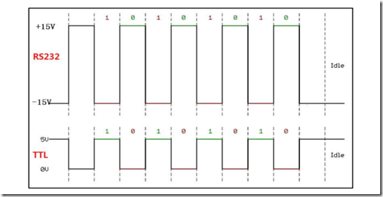
The difference between RS-232 and TTL level
TTL: generally the level directly from the microcontroller or chip, the high level is 5V or 3.3V, and the low level is 0
RS232: The low level is -15V, the high level is 15V, the peak difference is large, not 0 as the low level,
RS232 standard serial communication structure diagram
The controller AB can be understood as a chip, and the output is TTL level, which is converted into RS232 level through the level conversion chip (MAX3232, SP3232).
RS232 serial ports are generally used in industry, for preventing static electricity.... very good...
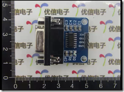
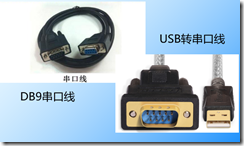
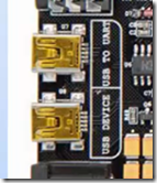
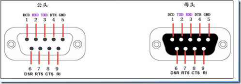
For STM32 boards without 232 serial ports, you can go to a treasure to buy a 232 serial port, which generally looks like this. (RXD TXD VCC GND The black small block is the level conversion chip, and the silver interface is the DB9 interface. The DB9 serial port first connects two DB9 Interface connection, connect RXD and TXD to the pins of the USTAR serial port of STM32 respectively, and connect VCC GND to the corresponding position of the board (Dupont line), or use a USB-to-serial line to connect (level conversion chip is CH340, PL2303, CP2102) computer On, need to install the driver.)
Native serial to serial
1. The native serial communication is mainly the communication between the controller and the serial device or sensor. It does not need to go through the level conversion chip to convert the level, and directly use the TTL level communication
2. GPS module, GSM module, serial port to WIFI module, HC04 Bluetooth module
Protocol layer
The basic composition of serial data packets
Start bit: represented by a logic 0 data bit
Stop Bits: Represented by 0.5, 1, 1.5 or 2 logic 1 data bits
Valid data: The valid data is immediately after the start bit, and the length of the valid data is usually agreed to be 5, 6, 7 or 89 bits long
Check digit: optional, for the anti-interference of the data.
The verification methods are divided into:
1-odd parity (odd), 2-even parity (even)
3-0 check (space), 4-0 check (mark)
5-No parity
Odd parity (odd) : The number of "1" in valid data and parity bits is odd
For example, an 8-bit valid data is: 01101001, at this time there are 4 "1" in total, in order to achieve the odd parity effect, the parity bit is "1", and the last transmitted data will be 8-bit valid data plus 1 digit check digit for a total of 9 digits
Even parity (even) : The number of "1" in the valid data and parity bit is an even number
For example, an 8-bit valid data is: 01101001, at this time there are 4 "1" in total, in order to achieve the even check effect, the check bit is "0", and the last transmitted data will be 8-bit valid data plus 1 digit check digit for a total of 9 digits
0 parity means that the parity bit is always "0" no matter what is in the valid data.
1 parity means that the check digit is always "1".
No check means that the data packet does not contain a check digit
