Preface: The content of this chapter is mainly to demonstrate the circuit design, simulation, synthesis and download using Verilog language under Vivado
Example: Counter

- Features: Using Xilinx Artix-7 XC7A35T chip
- Configuration method: USB-JTAG/SPI Flash
- Up to 100MHz internal clock speed
- Memory: 2Mbit SRAM N25Q064A SPI Flash (the old model of the sample picture is N25Q032A)
- General IO: Switch: x8LED: x16Button: x5DIP: x8 General expansion IO: 32pin
- Audio and video/display: 7-segment digital tube: x8 VGA video output interface Audio audio interface
- Communication interface: UART: USB to UART Bluetooth: Bluetooth module
- Analog interface: DAC: 8-bit resolution XADC: 2-way 12bit 1Msps ADC
Table of contents
0x00 Use D flip-flop to construct ring counter (self-circular shift register)
0x01 Twisted ring counter (Johnson counter)
Ⅰ. Pre-requisite knowledge
0x00 Use D flip-flop to construct ring counter (self-circular shift register)
The figure below is a counter circuit constructed by using D flip-flops. If A, B, C, and D are initially set to 1000, and the CP is connected to single pulse counting, the counter can realize one-hot counting.
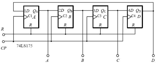
Ring Counter Principle
The reference procedure is as follows,
module circle_counter(rst_n, clk, cnt );
parameter CNT_SIZE = 8;
input rst_n;
input clk;
output [CNT_SIZE-1 : 0] cnt;
reg [CNT_SIZE-1 : 0] cnt;
always@(posedge clk)
    if(!rst_n)
        cnt <= 8'b0000_0001;  //初始值
    else
        cnt <= {cnt[0],cnt[CNT_SIZE-1 : 1]};//注意是循环移位,而非简单的移位
        //cnt <= cnt>>1;
Endmodule
In the figure below, the above circuit is modified with a 74LS10 three-input NAND gate, so that when the initial value is 0000, the counter state can automatically jump to 1000 at the next CP pulse.
Please summarize your self-starting experience. (Note: 74LS10 has a gate that acts as a NOT gate)

self-starting ring counter
The reference procedure is as follows:
module circle_counter(rst_n, clk, cnt );
parameter CNT_SIZE = 8;
input rst_n;
input clk;
output [CNT_SIZE-1 : 0] cnt;
reg [CNT_SIZE-1 : 0] cnt;
always@(posedge clk)
    if(!rst_n)
        cnt <= 8'b0000_0001;  //初始值
    else
        cnt <= {cnt[0],cnt[CNT_SIZE-1 : 1]};//注意是循环移位,而非简单的移位
        //cnt <= cnt>>1;
Endmodule
The above code is just a simple implementation, simulating the working method of the ring counter, without too much consideration of the self-starting problem.
For the ring counter, it is also called one-hot (one-hot code) counter in function. A 1 state at the output indicates a count.
The main disadvantage is that there is no effective use of the state of the circuit. For n bits, there are 2n-n states that are not utilized. In the application, this kind of counter is often used in the state coding of the state machine. For example, the counting sequence of the 4bit one-hot counter is: 0001-0010-0100-1000 cycle. Therefore, in most cases, this kind of counter is not called a counter, but a kind of state encoding.
If you want to design a circuit that can self-start (automatically transfer from an invalid state to a valid state and enter a valid cycle), you can refer to the experimental content of the state machine design in the additional experiment, and realize it by modifying the state logic. The essence is to change the secondary state of the invalid state. make it active.
0x01 Twisted ring counter (Johnson counter)
Basic principle: set an initial state, invert the highest bit, and use it as the input of the lowest bit, which can be obtained by shifting.
As shown in the picture:

Schematic diagram of twisted ring counter principle
Reference Code:
module john_counter(rst_n, clk, cnt );
parameter CNT_SIZE = 4;
input rst_n;
input clk;
output [CNT_SIZE-1 : 0] cnt;
reg [CNT_SIZE-1 : 0] cnt;
always@(posedge clk)
    if(!rst_n)
        cnt <= 4'b0000 ;  //初始值
    else
        cnt <= {~cnt[0],cnt[CNT_SIZE-1 : 1]}; //注意是循环移位,而非简单的移位
endmodule
Ⅱ. Verilog implementation:
0x00 Ring counter
Design code:
module circle_counter(rst_n, clk, cnt );
parameter CNT_SIZE = 8;
input rst_n;
input clk;
output [CNT_SIZE-1 : 0] cnt;
reg [CNT_SIZE-1 : 0] cnt;
always@(posedge clk)
 if(!rst_n)
 cnt <= 8'b0000_0001;
 else
 cnt <= {cnt[0],cnt[CNT_SIZE-1 : 1]};
endmodule
Simulation code:
module test();
reg rst_n,clk;
wire [7:0]cnt;
circle_counter uut(.rst_n(rst_n),. clk(clk),. cnt(cnt));
initial begin
		clk = 'b0;
		rst_n = 'b0;
		# 10
		rst_n = 'b1;
        # 2000
                $finish;
            end

            always #5 clk = ~clk;
endmodule
Simulation waveform diagram:

0x01 twist ring counter
Designing Documents:
module john_counter(rst_n, clk, cnt );
parameter CNT_SIZE = 4;
input rst_n;
input clk;
output [CNT_SIZE-1 : 0] cnt;
reg [CNT_SIZE-1 : 0] cnt;
always@(posedge clk)
if(!rst_n)
cnt <= 4'b0000 ;
else
cnt <= {~cnt[0],cnt[CNT_SIZE-1 : 1]};
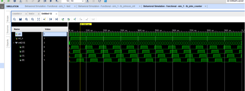
endmoduleSimulation file:
module tb_john_counter();
	reg clk, rst_n;
	wire [3:0] cnt;
john_counter uut(.rst_n(rst_n),. clk(clk),. cnt(cnt));
	initial begin
		clk = 'b0;
		rst_n = 'b0;
		# 10
		rst_n = 'b1;
		# 2000
		$finish;
	end
	always #5 clk = ~clk;
Endmodule
Simulation waveform diagram: