0 Preface
This series of blogs is mainly used to record the learning process, if there is any error, welcome to point out.
Chip: xc7z020clg400-1;
development board: Red Panda 7020 development board;
development environment: Vivado 18.3;
system environment: Windows 11;
1、HLS
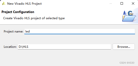
New Construction
The name can be chosen at will, the path should be remembered
add files
Add a cpp file written in HLS language. After the addition is complete, browse the file, extract the Top Function file (the file name here corresponds to the subsequent IP name) and then add TestBench Files (
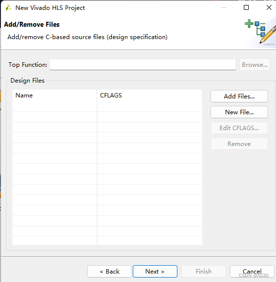
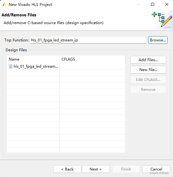
used to test and call the former CPP file), you also You don’t need to add it, but it can also be packaged comprehensively
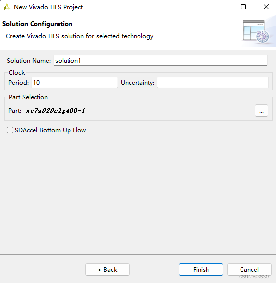
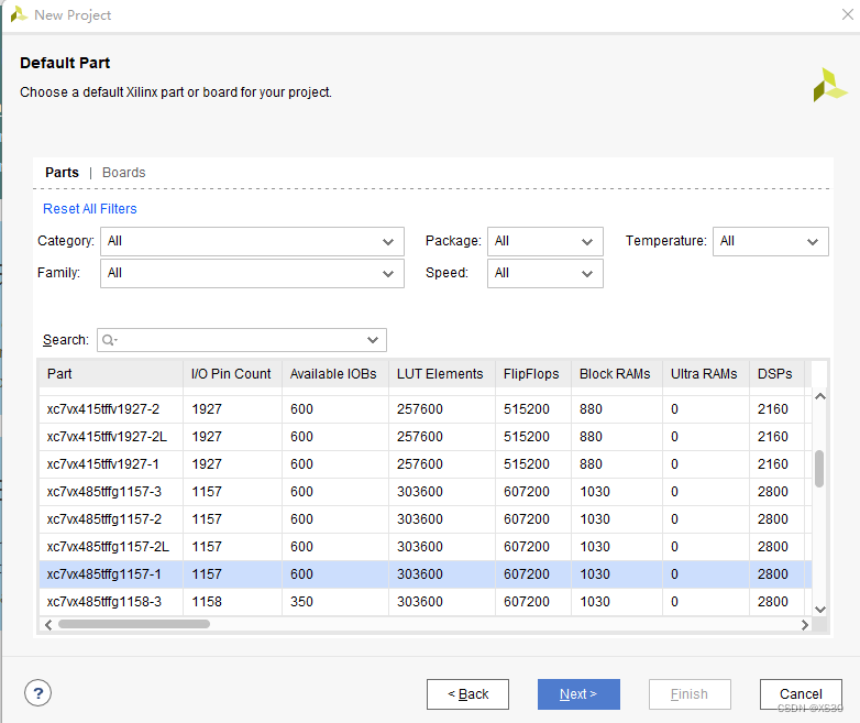
select chip
the code
#include "stdio.h"
#include "ap_int.h"
#define CLK_FREQ  1
void hls_01_fpga_led_stream_ip(ap_int<4> &led)
{


	#pragma HLS interface ap_none port=led
	#pragma HLS interface ap_ctrl_none port=return
	static int led_number=0;
	static long cnt_reg=0;
	if(cnt_reg<CLK_FREQ)cnt_reg++;
	else
	{


		cnt_reg=0;
		if(led_number<3)led_number++;
		else led_number=0;
	}
	if(led_number==0)
	{


		led=0x1;
	}
	else if(led_number==1)
	{


		led=0x2;
	}
	else if(led_number==2)
	{


		led=0x4;
	}
	else if(led_number==3)
	{


		led=0x8;
	}
}
Synthesis
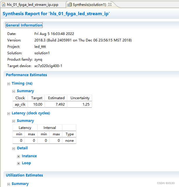
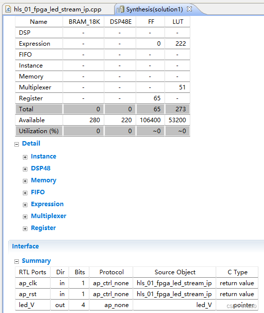
Select the synthesis button (C Synthesis)
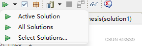
on the top menu bar by default . After the first synthesis is completed, if there is no problem, it will automatically jump to the synthesis report interface, where you can see the port and resource usage .
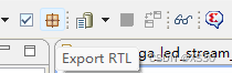
Pack IP (Export RTL)
Click this icon in the menu bar to export.
The dialog box that pops up can
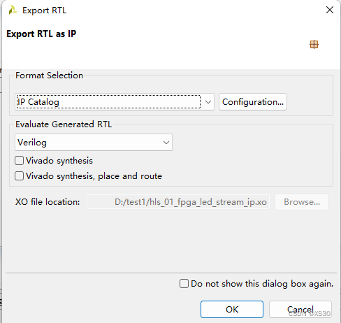
be exported by default.
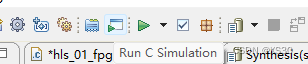
Conduct testing/simulation (Simulation)
This step is not necessary, but it has obvious advantages for the actual deployment of the later code, and the code can be tested by this means.
If the IP code is a function block/function; the tb file is the main function that calls the IP.
#include "stdio.h"
#include "ap_int.h"
extern void hls_01_fpga_led_stream_ip(ap_int<4> &led);
int main(void)
{
int i=0;
unsigned int tmp_print_data=0;
ap_int<4> led=7;
for(i=0;i<1000;i++)
{
hls_01_fpga_led_stream_ip(led);
tmp_print_data=led&0xf;
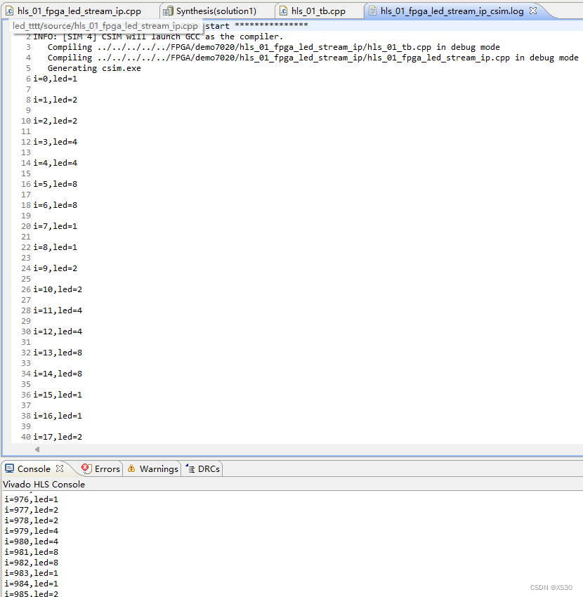
printf("i=%d,led=%d\r\n",i,tmp_print_data);
}
return 0;
}
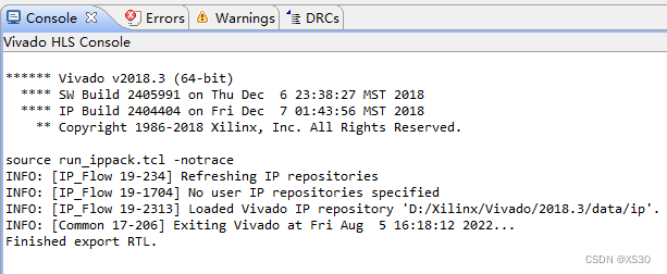
Then click the icon to perform simulation
By viewing the log file or the output information of the console window, determine whether the program is running correctly.
2、Living
create project
Next all the way, until here choose your own chip xc7z020clg400-1 (this is wrong, it will cause the IP to not be loaded correctly, this choice can be modified twice in the software)
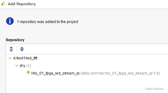
Import IP
Click Setting on the left (here you can modify the chip model)
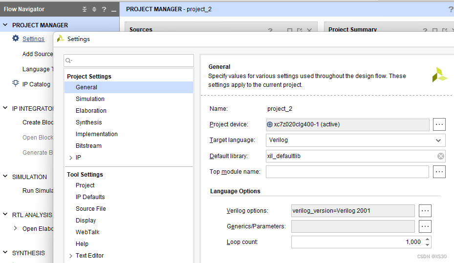
IP—>Repository—>Add—>select the HLS project path
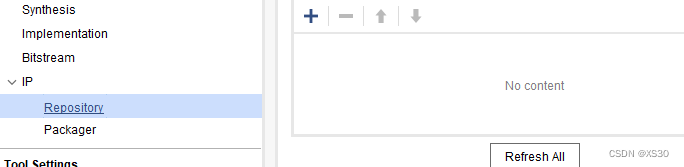
and click OK, and the addition is complete (note here that the icon in front of the IP name must be yellow). OK, if it is gray, follow-up work will not be possible, please check whether the chips do not match.
Click OK to close the interface.
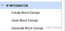
Creating Block Designs
Click the plus sign on the right to add the IP just
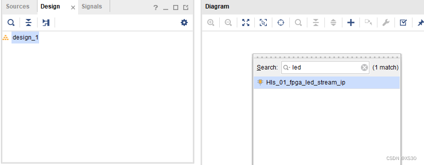
imported
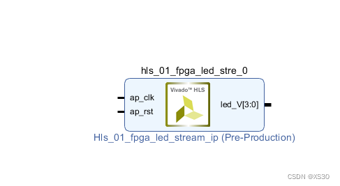
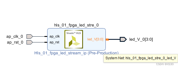
Connect and configure
Since what we want to achieve is a simple running light function, the required clock signal and reset signal are provided by external pins, and the LED also needs to be configured with reference to the schematic diagram, so in the block design, we need to put all port to configure.
Select the corresponding pin and use the shortcut key of Ctrl+T to quickly generate a port.
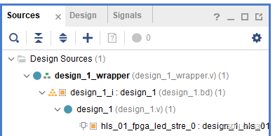
After the wiring is completed, we need to convert the block design to HDL Wrapper
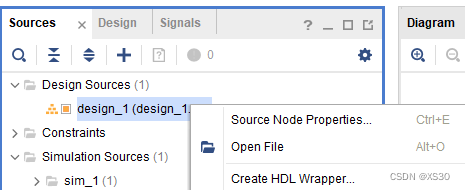
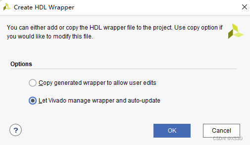
and create it
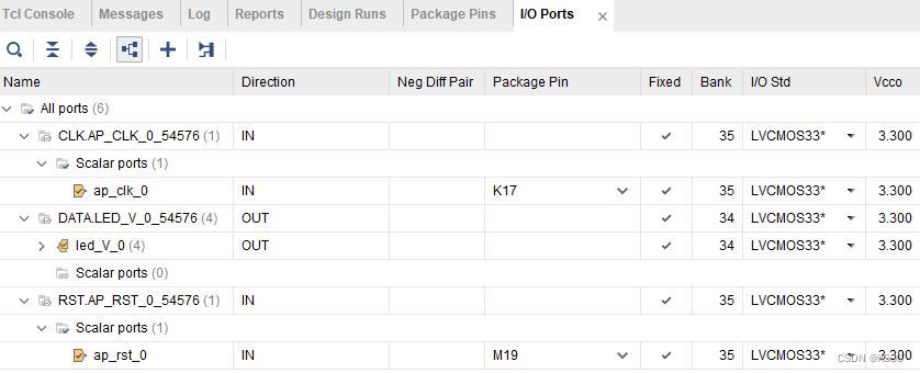
Allocation of pins
Click Open Elaborated Design in the left menu, and the dialog box that pops up is OK by default.
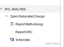
The page pops up.
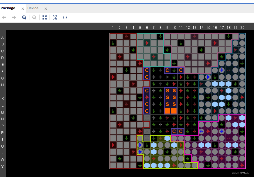
Configure the pins according to the figure below, then press Ctrl+S to save and name it
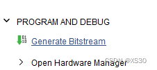
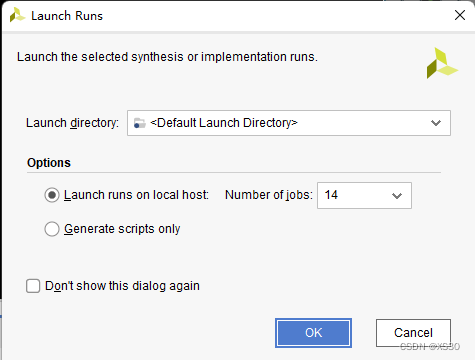
Generate Bit file
Here 14 refers to the number of computer CPU cores.
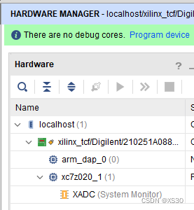
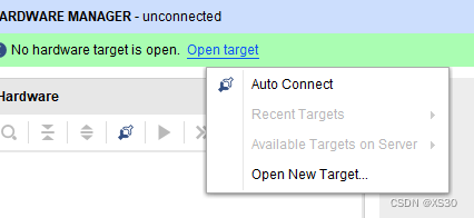
You can select Open Hardware Manager to open this interface, then select Open target, select Auto
Burn test
Select Program device to burn.