Detailed serial communication
- Several basic concepts involved in communication
- Synchronous communication and asynchronous communication
- Level signal and differential signal
- Parallel and serial interface
- Basic concepts involved in serial communication
- Asynchronous, level signal, the serial
- RS232 level and TTL level
- Baud Rate
- Start bit, data bits, parity, stop bits
- The basic principle of serial communication
- Full-duplex, half duplex and simplex communication
- Three communication lines: Rx Tx GND
- Send and receive both pre-ordained communication parameters
- Transmitting channel information in a binary stream in the manner
- Detailed STM32 serial communication
- 1. The serial clock enable pin of GPIOA
- 2. Enable serial clock, the serial mount AHB2
- 3. The pin serial port multiplexed serial interrupt line
- 4. The normal operation of the GPIO pins initialize the serial port
- The serial port initialization parameters
- 6. Set the serial port interrupt priority grouping
- 7. Writing the serial interrupt service routine
- 8. The send function to write custom
- 9. The preparation of the main function
- 10. Verify Download
- 11. serial debugging assistant to send data to the microcontroller
- 11. The modified main function
Serial communication is asynchronous serial communication inside. Serial communication is with respect to the parallel communication. Serial is the fact that the existence of a thing, such as DB9 connectors.
Serial communication baud rate which, in fact, is the bit rate. If these two points is not very clear to you, then, a good read on.
Several basic concepts involved in communication
Synchronous communication and asynchronous communication
(1), the difference between synchronous and asynchronous: in short, the sender and the recipient is called synchronization in accordance with a clock tick work, the sender and the recipient is no uniform beat the clock, and each according to its own rhythm of work is called asynchronous .
(2), synchronous communications, according to a unified communication parties beats work so well with; generally require a sender to a receiver clock signal simultaneously transmits transmission information, to arrange the receiver clock signal in accordance with its own rhythm to its sender. Synchronous communication with both the exchange of information when the communication frequency is fixed, or regular traffic. Synchronization with a clock signal transmission. As -SPI, IIC communication.
(3), also known as asynchronous communication asynchronous notification. When both the communication frequency is not fixed (3ms sometimes a transceiver, a transceiver and sometimes three days) is not suitable for synchronous communication, and for asynchronous communication. Asynchronous communication recipient need not have been concerned about the sender, the start signal will be the first to start a recipient of information when the sender needs to send information, the recipient after the start signal is received immediately followed is considered valid information only will begin to pay attention to receiving information until it receives the sender sent me end mark. Asynchronous Communication: without a clock synchronization signal. As · UART (Universal Asynchronous Receiver Transmitter), a single bus.
Level signal and differential signal
(1), the level and differential signals are used to describe transmission of a communication line. That is how to express on the communication line 1 and 0.
(2), level of a signal transmission line has a reference level line (typically the GND), and the signal value of the signal line is a signal line from the reference level flat line voltage difference is determined.
(3), a differential signal transmission line is not a reference level, are all the signal lines. 1 and 0 are then expressed by the voltage difference between signal lines.
Summary: The difference in level between the two communication line level signals susceptible to interference, transmission is prone to failure; differential signal is not susceptible to interference and therefore the transmission quality is stable, usually modern communication using a differential signal, the signal level of almost no . Summary 2: seem the same number of ones of the communication line, the signal level of the differential signal is faster than that; but the actual difference signal is fast, since the differential signal interference ability, and therefore a shorter transmission period.
Parallel and serial interface
(1), serial, parallel, mainly considering the number of the communication lines, that is, the sender and receiver of information may be simultaneously transmitted number
(2), for example at the level of the signal, a reference level line +1 signal line can be transmitted binary one; if we have three wires (2 + 1 signal lines root reference line) can be simultaneously transmitted 2-bit binary; If you want to simultaneously transmit 8-bit binary requires nine lines.
(3) In the differential signal, two lines (differential another) may send a binary simultaneously; 8-bit binary If transmit simultaneously, requires 16 wires.
Summary: sounds like a parallel interface is faster than the serial interface (serial interface can only send a binary, and parallel interface can send binary number) to be better; but in fact a serial interface is king, with the relatively wide. Since the signal line more economical, but also requires less transmission line, lower cost; and communication performance can be improved by increasing the overall speed serial communication does not necessarily have to be parallel.
Summary: asynchronous, serial, differential, such as USB and network communication better.

Basic concepts involved in serial communication
Asynchronous, level signal, the serial
(1) Asynchronous: between the sender and receiver serial communication is not uniform clock signal.
(2) the level of signal: serial communication occurs earlier time, lower rate, transmission distance close, so that the interference is not yet clear, and therefore the time in which the electric signal transmission level. The late transmission protocols are changed to a differential signal transmission.
(3), a serial communication: while only transmit serial communication per 1 bit
RS232 level and TTL level
(1) level signal is obtained by subtracting the reference line level of the signal line voltage obtained level difference, the voltage difference determines the value of the transmission is 1 or 0.
(2) When V represents how much the level of the signal 1, V represents the number 0 is not fixed, depending on the level criteria. For example RS232 level of -3V ~ -15V represents 1; + 3 ~ + 15V represents 0; TTL + 5V level is represented 1,0V represents 0.
(3) regardless of which level is to represent the transmission line and 0. 1 except that different environments and conditions applied. RS232 level is defined relatively large, a large interference fit, the case where distance; small TTL level voltage range, suitable for short distance and the interference is small.
(4) behind our desktop computer serial port RS232 socket interface is, when using the serial port on the industry are used, the transmission distance of less than 15 meters; the TTL level is generally used between the circuit board inside two chips.
(5) for programming, RS232 or TTL level of the transmission is no difference in level. So a more meaningful level standard for hardware engineers, software engineers, and can be as long as some knowledge. (The TTL level RS232 level mixed access is not possible)


Baud Rate
(1) a very important parameter to measure the communication performance is the communication rate, typically at the bit rate (the Bitrate) to indicate that the number of bits transmitted per second, bits per second (bit / s). The concept is easy to be confused with the bit rate is "baud." (Baudrate), which indicates how many per second transmission symbol. The symbol is a conceptual modulated communication signal, communication same time interval used to represent a binary number notation, such signals are referred to as symbols. As is common in the communications transmission, with 0V 0,5V numeral number 1 indicates, then one symbol may represent two states 0 and 1, the one symbol equal to a binary bit, the baud rate at this time the size of the bit concordance rate; if transmission in the communication, there is 0V, 2V, 4V and 6V 00,01,10,11 each represent a binary number, each symbol can represent four states, i.e. two binary bits, the symbol the number is half the number of bits of binary, this time the baud rate is half the bit rate. Because many common communication symbol two states are represented, it is often expressed directly to the baud bit rate. Can be transmitted per second example 9600 bits (the time required to transmit one bit is 1/9600 second, i.e. 104us), 9600. However, because the bit rate is one symbol is represented by two states, the bit rate = The baud rate. It said baud rate is also typically 9600
(2) serial communication baud rate can be set arbitrarily, but should be selected to some value. Generally the most common baud rate is 9600 baud or 115200. Why not just specify? Mainly because: first, the two sides must first set the same communication baud rate in order to communicate successfully, if the sender and recipient in accordance with different communication baud rates are simply not receive, so the baud rate is the best we known rather than arbitrarily designated. Second, the commonly used baud rates through long-term development, to form a consensus, we used is 9600 or 115200.
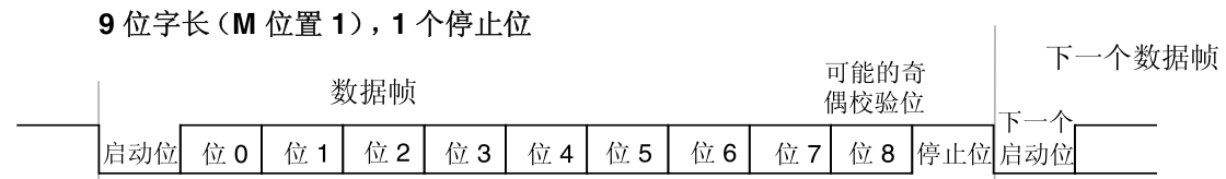
Start bit, data bits, parity, stop bits
(1) serial communications, a transceiver is a period of one cycle, no transmission period n bits. This is called a cycle a communication unit, a communication unit is composed of: a start bit + data bits + parity bit + stop bits thereof.
(2) the start bit indicates the sender to send a communication start unit; valid data bit is a bit of information sent by communication unit; parity bit is used for parity data bits, the data bits in order to prevent erroneous; stop bits It is used to represent the sender communication unit end flag is present.
(3) is defined as the start bit of serial communication standards specified in advance, by the level change to reflect the communication line.
(4) data bits are valid data really want to send this communication, the number of valid data is sent once serial communication can be set (there are usually optional at 6,7,8,9,99% we are select the 8 data bits. since we generally sent by text message serial ASCII code are encoded in ASCII and a character just coded into 8 bits.)
(5) parity bit is used for parity bits to the data check (checksum of the payload data to be combined by one bit, the sum is odd parity bit is set to 1, the sum of the even parity bit is set to 0), the bit inversion can be prevented to some extent.
- Odd parity check bit and valid data is required in the number of "1" is an odd number, such as an 8-bit data is valid: 01101001, then a total of four "1", in order to achieve the effect of odd parity, school parity bit is "1", the data transmission will be the last 8 valid data bits plus 1 parity bit in total 9 bits.
- Even parity and odd parity in claim contrary, the requested frame number data and the parity bit "1" is an even number, such as a data frame: 11001010, then the data frame number "1" is four, so even the parity bit is "0."
- 0 check is valid regardless of what the data is, the parity bit is always "0", 1 parity check bit is always "1."
- In the case where no parity, data packet does not contain a parity bit.
(6) the stop bit is defined serial communication standard designated in advance, by the level change to reflect the communication line. Common are one stop bit, 1.5 stop bits, 2 stop bits. In 99% of cases it is with a stop bit.
Summary : because when serial communication is asynchronous communication, the communicating parties have agreed in advance good communication parameters, communication parameters include: baud rate, data bits, parity, stop bits (serial communication start bit definition is unique , it is generally not selected)
The basic principle of serial communication
Full-duplex, half duplex and simplex communication
(1) is unidirectional simplex, duplex transceivers that both sides simultaneously, while only one direction but the direction may be changed called half-duplex
(2) If A sends only the receiving simplex B, A sends B B receive or send A receive (two directions can not) be called half-duplex, A hair hair B A B receive simultaneously receive full duplex call.

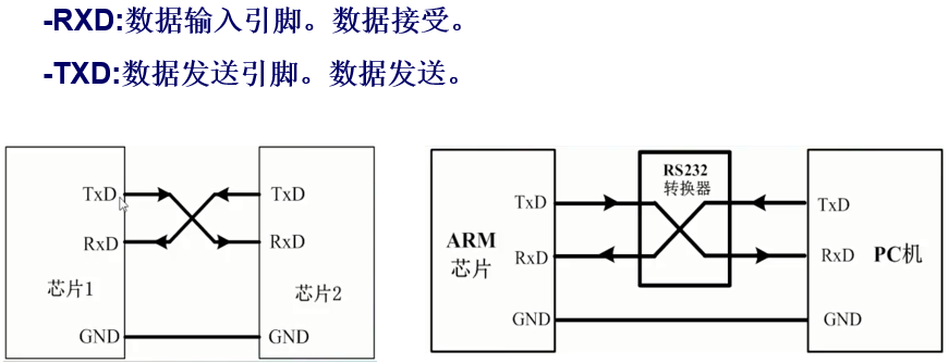
Three communication lines: Rx Tx GND
(1) any communication information delivery vehicle, either wired or wireless.
(2) Serial communication wired communication, by serial communication lines.
(3) serial communication line requires a minimum of two (GND signal lines), simplex communication may be implemented, it may be used three communication lines (Tx, Rx, GND) to achieve full-duplex.
Send and receive both pre-ordained communication parameters
(1) serial communication belonging to grass-roots base of communication protocols, it does not itself to negotiate communication parameters, the communication needs to communicate before the two sides agreed in advance good communication parameters (baud rate, data bits, parity, stop bits, etc.)
any one of the key parameters (2) serial communication setting error will cause communication failures. Such as baud rate adjustment is wrong, no problem sending the sender, the recipient can receive, but received all garbled ???
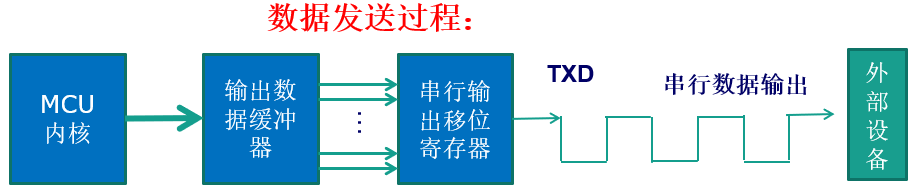
Transmitting channel information in a binary stream in the manner
(1), the sender of the serial communication (time is fixed at 1 / baud rate, in seconds) the valid information (1 or 0) is placed to the communication line, one by one binary bit transmitted at regular time intervals.
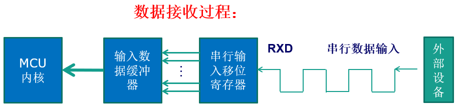
(2) the recipient (the start time starts to read the start flag, the time interval determined by the baud rate) level communication line read level to distinguish sent to me is 1 or 0 through the timing. Sequentially reading data bits, parity, stop bits, the stop bit indicates that a communication unit (frame) ends, then the middle of the length of the variable is non-communication time (transmission side immediately transmits the second possible frame, also probably for a long time do not send the second frame, which is called asynchronous communication), is the second frame down ?????
summarize : first, the baud rate is very important, the whole communication baud wrong went wrong; data bits , parity, stop bits is also very important, otherwise illegible data.
Third, regardless of hair through the serial port number, or text or command or something, you have to send to encode the content, and then encoded into binary-by-bit transmission.
(3) serial character are generally transmitted, the general character of the ASCII code are coded, so normally are 8 data bits, just a convenient transmit a byte.
Detailed STM32 serial communication
Serial communication physical layer standards and there are many variants, mainly on the standard RS-232, RS-232 standard specifies the level of the main uses standard signal, and the signal communication interface. Because we have a common market, development boards that are talking about an agreement on a standard RS-232 serial port communications.
What we have here is not to talk about the structure, which go directly to the data sheet is like, talk about the configuration process step, so that with confidence, aware of.
1. The serial clock enable pin of GPIOA
RCC_AHB1PeriphClockCmd(RCC_AHB1Periph_GPIOA,ENABLE);
2. Enable serial clock, the serial mount AHB2
RCC_APB2PeriphClockCmd(RCC_APB2Periph_USART1, ENABLE);
3. The pin serial port multiplexed serial interrupt line
/*连接 PA10 复用到 USART1_Rx*/
GPIO_PinAFConfig(GPIOA,GPIO_PinSource10,GPIO_AF_USART1);
/*连接 PA9 复用到 USART1__Tx*/
GPIO_PinAFConfig(GPIOA,GPIO_PinSource9,GPIO_AF_USART1);
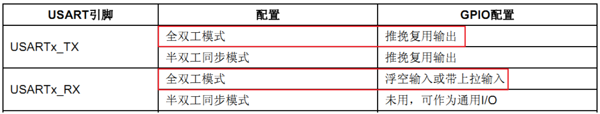
STM32 has a lot of built-in peripherals, these peripherals external pins are multiplexed with GPIO. In other words, if a GPIO can be reused as a built-in peripheral function pin, then when the time GPIO as built-in peripheral use, is called multiplexing. Such as serial transmission and reception pin 1 is PA9, PA10, when we put PA9, PA10 is not used as GPIO, and used to send alternate function pin serial port 1 receiver, called port multiplexing.
4. The normal operation of the GPIO pins initialize the serial port
/* GPIO初始化 */
GPIO_InitStructure.GPIO_OType = GPIO_OType_PP;
GPIO_InitStructure.GPIO_PuPd  = GPIO_PuPd_UP;
GPIO_InitStructure.GPIO_Speed = GPIO_Speed_50MHz;
/* 配置Tx引脚为复用功能  */
GPIO_InitStructure.GPIO_Mode = GPIO_Mode_AF;
GPIO_InitStructure.GPIO_Pin =  GPIO_Pin_9  ;
GPIO_Init(GPIOA, &GPIO_InitStructure);
/* 配置Rx引脚为复用功能 */
GPIO_InitStructure.GPIO_Mode = GPIO_Mode_AF;
GPIO_InitStructure.GPIO_Pin =  GPIO_Pin_10;
GPIO_Init(GPIOA, &GPIO_InitStructure);
The serial port initialization parameters
USART_Init serial port initialization function is achieved by ().
/* 波特率设置:115200 */
USART_InitStructure.USART_BaudRate = 115200;
/* 字长(数据位+校验位):8 */
USART_InitStructure.USART_WordLength = USART_WordLength_8b;
/* 停止位:1个停止位 */
USART_InitStructure.USART_StopBits = USART_StopBits_1;
/* 校验位选择:偶校验 */
USART_InitStructure.USART_Parity = USART_Parity_No;
/* 硬件流控制:不使用硬件流 */
USART_InitStructure.USART_HardwareFlowControl = USART_HardwareFlowControl_None;
/* USART模式控制:同时使能接收和发送 */
USART_InitStructure.USART_Mode = USART_Mode_Rx | USART_Mode_Tx;
/* 完成USART初始化配置 */
USART_Init(USART1, &USART_InitStructure);
/* 使能串口 */
USART_Cmd(USART1, ENABLE);
/*开启中断 接收到数据产生中断 进入中断服务函数 */
USART_ITConfig(USART1, USART_IT_RXNE, ENABLE);
Initialization parameters need to be set as: baud rate, word length, stop bits, parity bit, hardware flow control mode (sending and receiving).
There's USART_Cmd (); function is well understood, it is that the serial port. USART_ITConfig (); interrupt response is to open up, and there's a second entrance parameters we generally write that USART_IT_RXNEis open to receive interrupt that program at the end of the transmission data to generate an interrupt, the interrupt service functions transferred.
6. Set the serial port interrupt priority grouping
Previous chapter we say, as long as you use the program inside the interrupt, you must configure the serial port priority packet. But we sometimes we find ourselves in the manufacturer's serial number is not configured in the serial port interrupt routine priority grouping, it is because he has only one serial port interrupt program is no so-called priority, with no configuration, the program only interrupts.
NVIC_InitStructure.NVIC_IRQChannel = USART1_IRQn;
NVIC_InitStructure.NVIC_IRQChannelPreemptionPriority = 3;//抢占优先级3
NVIC_InitStructure.NVIC_IRQChannelSubPriority = 0;       //子优先级0
NVIC_InitStructure.NVIC_IRQChannelCmd = ENABLE;
NVIC_Init(&NVIC_InitStructure);
7. Writing the serial interrupt service routine
This function is very important, since it is necessary to interrupt the implementation of the serial interrupt service routine to go, follow the appropriate instructions.
void USART1_IRQHandler(void)
{
	if(USART_GetITStatus( USART1, USART_IT_RXNE ) != RESET)//获取接收中断标志位(接收到的数据必须是0x0d 0x0a结尾)
	{
	  Res = USART_ReceiveData( USART1 );
			if((USART_RX_STA&0x8000)==0)//接收未完成
			{
			if(USART_RX_STA&0x4000)//接收到了0x0d
				{
				if(Res!=0x0a)USART_RX_STA=0;//接收错误,重新开始
				else USART_RX_STA|=0x8000;	//接收完成了
				}
			else //还没收到0X0D
				{
				if(Res==0x0d)USART_RX_STA|=0x4000;
				else
					{
					USART_RX_BUF[USART_RX_STA&0X3FFF]=Res ;
					USART_RX_STA++;
					if(USART_RX_STA>( USART_Rec_Len-1))USART_RX_STA=0;//接收数据错误,重新开始接收
					}
				}
			}
	}
}
7.1 interrupt service function names are not just played, USART1_IRQHandler represents a serial port interrupt service function, function names can be found in the startup file startup_stm32f10x_hd.s file.
7.2 if (USART_GetITStatus (USART1, USART_IT_RXNE )! = RESET) EENOW see the name, the serial port interrupt flag obtained, determines whether or not a serial port receive interrupt occurs, if the serial port receive interrupt, received serial data is read.
7.3 Res = USART_ReceiveData (USART1); 1 read from the assigned serial received data to the variable Res.
7.4 Simple receiving protocol. Through the if statement, a complex array USART_RX_BUF [], a receive status register USART_RX_STA (this register is actually a global variable, added by the reader itself. Since it functions as a similar register, let us call this register) to achieve serial data the reception management. USART_RX_BUF size defined by USART_Rec_Len, i.e. a received data must not exceed the maximum USART_Rec_Len bytes. USART_RX_STA is receiving a status register.

Hair is received from the computer over the serial debugging assistant data, the received data stored in USART_RX_BUF while the reception state register (USART_RX_STA) counting the number of valid data is received, when a carriage return (Enter representation It consists of 2 bytes: ASCII carriage return and line feed code is the ASCII code 0X0D is 0X0A) 0X0D first byte, the counter will not increase, waiting 0X0A, and if not to 0X0A it is considered the reception failed once again to receive the next start. If 0X0A successfully received, the first mark 15 USART_RX_STA so complete a received bit is cleared, and waits for the other programs, so that the next reception start, and if not received 0X0D delay, then the received data exceeds USART_Rec_Len when the preceding data is discarded, re-received.
8. The send function to write custom
This custom function to send is that we send the data directly in the program to serial debugging assistant, this custom function and interrupt service function has nothing to do, because the interrupt service function is used to receive data that we send to the microcontroller through the serial debugging aid data, need to use an interrupt service routine. In other words, if you just want to send data to the microcontroller through the serial debugging assistant, then you do not need to write the interrupt service routine. But this approach does not make sense, we mainly use the serial port is receiving data, just send a little sense data.
/***************** 发送一个字符 **********************/
static void Uart_SendByte(uint8_t ch)
{
/* 发送一个字节数据到USART1 */
USART_SendData(USART1,ch);
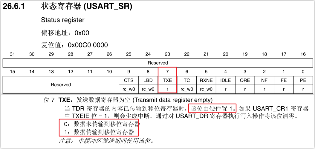
/* 等待发送完毕 */
while (USART_GetFlagStatus(USART1, USART_FLAG_TXE) == RESET); //获取发送状态
}
/***************** 发送字符串 **********************/
void Uart_SendString(uint8_t *str)
{
uint8_t k=0;
do
{
Uart_SendByte(*(str + k) );
k++;
} while(*(str + k)!='\0');
}
/***************** 指定长度的发送字符串 **********************/
void Uart_SendStr_length(uint8_t *str,uint32_t strlen )
{
uint8_t k=0;
do
{
Uart_SendByte( *(str + k) );
k++;
} while(k < strlen);
}
We are here to prepare the three main functions are functions: send a character to the microcontroller, sends a string to the microcontroller sends a specified length to the microcontroller.
Code is very short, not much explanation. When sending byte function uses acquisition state, the transmission data acquisition status register bits 7, when the number 1 is transmitted from the shift register. The transmission can be sent over.
9. The preparation of the main function
int main(void)
{
	char ch;
	NVIC_PriorityGroupConfig(NVIC_PriorityGroup_2);
	USART1_Init();
	Uart_SendString( (uint8_t *)"这条数据是来自单片机发送的数据\n" );
	Uart_SendString( (uint8_t *)"输入数据并以回车键结束\n" );
	while(1)
	{	}
}
First, we need to call NVIC_PriorityGroupConfig (NVIC_PriorityGroup_2); completion interrupt priority group setting. Then call USART1_Init USART function to complete initial configuration, including GPIO configuration, configure the USART receive interrupt use and so forth. Then you can call the character transmission function to send data to the serial debugging assistant. Finally, the main function does nothing, just quietly waiting for the USART receive interrupt, and interrupt service function to return data.
10. Verify Download
Ensure the development board related hardware is connected correctly, connect the serial debug interfaces with the computer usb development board with a USB cable, open the serial debugging assistant at the computer end, to configure the baud rate, parity, data bits, stop bits. The compiled program is downloaded to the development board, then the serial debugging assistant can receive data sent over the development board. We send in the serial debugging assistant enter any character area, click on the Send button, you can immediately see the same characters in the serial debugging assistant reception area. Because I do not have the hands of a serial cable at home, so we can not demonstrate a screenshot.
11. serial debugging assistant to send data to the microcontroller
SCM and receive, execute a corresponding instruction. We can not just send data to serial debugging assistant, we can also send data in serial debugging assistant to the controller, the controller work program to the next step according to the received data. First of all, let's write a program to achieve development board to communicate with the computer, send a bunch of string through the USART in the development of the electric board to the computer, and then into the development board interrupt reception waiting state, if the computer has to send data over the development board will generate an interrupt, the interrupt service routine we receive the data, and the data is returned immediately sent to the computer.
//重定向c库函数printf到串口,重定向后可使用printf函数
int fputc(int ch, FILE *f)
{
		/* 发送一个字节数据到串口 */
		USART_SendData(USART1, (uint8_t) ch);
		/* 等待发送完毕 */
		while (USART_GetFlagStatus(USART1, USART_FLAG_TXE) == RESET);
		return (ch);
}

//重定向c库函数scanf到串口,重写向后可使用scanf、getchar等函数
int fgetc(FILE *f)
{
		/* 等待串口输入数据 */
		while (USART_GetFlagStatus(USART1, USART_FLAG_RXNE) == RESET);
		return (int)USART_ReceiveData(USART1);
}
In the C language standard library, fputc internal function is a function of the printf function, function is the character ch f written to the file pointer points to the file of the current write pointer position, simple understanding is write characters to a specific file. We use the USART function re-edit function fputc content, to achieve a similar " write " function. fputc fgetc function and function is very similar to continually read the characters. When using scanf function note character input format.
Another point to note, using fput and fgetc function reaches redirect input and output C language standard library functions must MDK project options on the "Use MicroLIB" tick, MicoroLIB default C library is an alternative library, it the standard C library has been highly optimized to make the code less, take up less resources. Using printf, scanf function need to include stdio.h header file in the file.

11. The modified main function
int main(void)
{
	char ch;
	NVIC_PriorityGroupConfig(NVIC_PriorityGroup_2);
	LED_Init();
	USART1_Init();
	Uart_SendString( (uint8_t *)"这条数据是来自串口发送的\n" );
	Uart_SendString( (uint8_t *)"输入数据并以回车键结束\n" );
	while(1)
	{
		ch=getchar();
		printf("接收到字符:%c\n",ch);
		switch(ch)
		{
			case '1':
			    printf("LED灯亮");
			    GPIO_ResetBits(GPIOH,GPIO_Pin_12);//PH12接了一个LED灯
			    break;
			default:
			    break;
		}
	}
}
Programming explain this point serial communication is over, now you yet?

