I learned the basic concepts of DMA last time, but I still don’t understand the application of DMA+serial port. The code I wrote doesn’t work well, so let’s put it in the back first. Here, I will learn the knowledge of the general-purpose timer GPTM.
Article directory
1. What is a timer?
TIM (Timer) timer
The timer can count the input clock and trigger an interrupt when the count value reaches the set value. The time base
unit of the 16-bit counter, prescaler, and automatic reload register, under the 72MHz count clock It can achieve a maximum timing of 59.65s. It
not only has the basic timing interrupt function , but also includes internal and external clock source selection , input capture , output comparison , encoder interface , master-slave trigger mode and other functions
. According to the complexity and application scenarios, it is divided into advanced There are three types of timers, general timers, and basic timers.
The advanced timer module contains a powerful 16-bit auto-reloadable timer (TIM1, TIM8, TIM9, and TIM10) The
general-purpose timer module contains a 16-bit auto-reloadable timer (TIM2, TIM3, TIM4, and TIM5)
Basic The timer module contains a 16-bit auto-reloadable timer (TIM6 and TIM7).
2. Universal timer
1. Main features
The main features of the general-purpose timer include:
16-bit auto-reload counter, supporting up-counting mode, down-counting mode and up-down counting mode
16-bit prescaler, frequency division coefficient dynamically adjustable from 1 to 65536
Supporting four channels Independent comparison capture channel
Each comparison capture channel supports multiple working modes, such as: input capture, output comparison, PWM generation and single pulse output
Support external signal control timer
Support using DMA in multiple modes to
support incremental encoding, Cascading and synchronization between timers
2. The basic structure of the basic timer
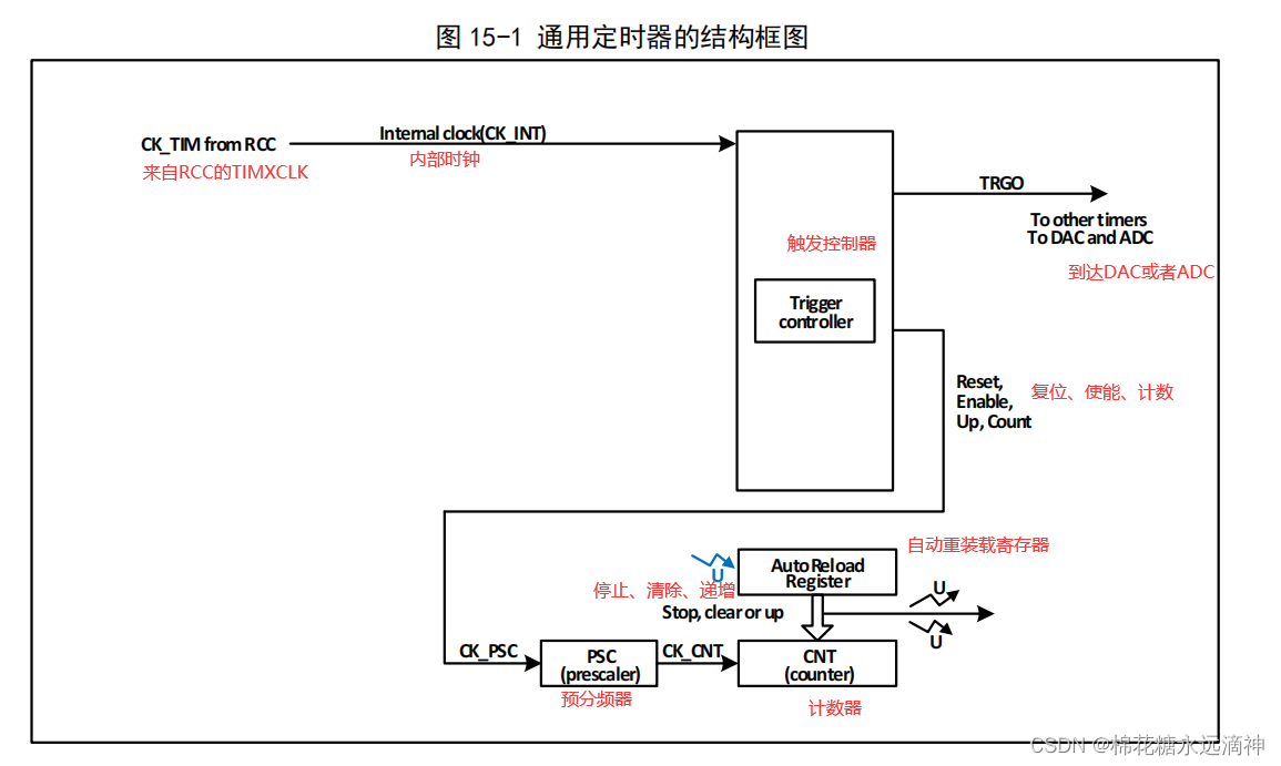
The structure of the basic timer can be roughly divided into two parts, namely the input clock part and the core counter part .
(1) Input clock part:
The internal clock CK_INT is generally the main frequency of the system, such as 72MHz.
(2) The core of the general-purpose timer is a 16-bit counter (CNT).
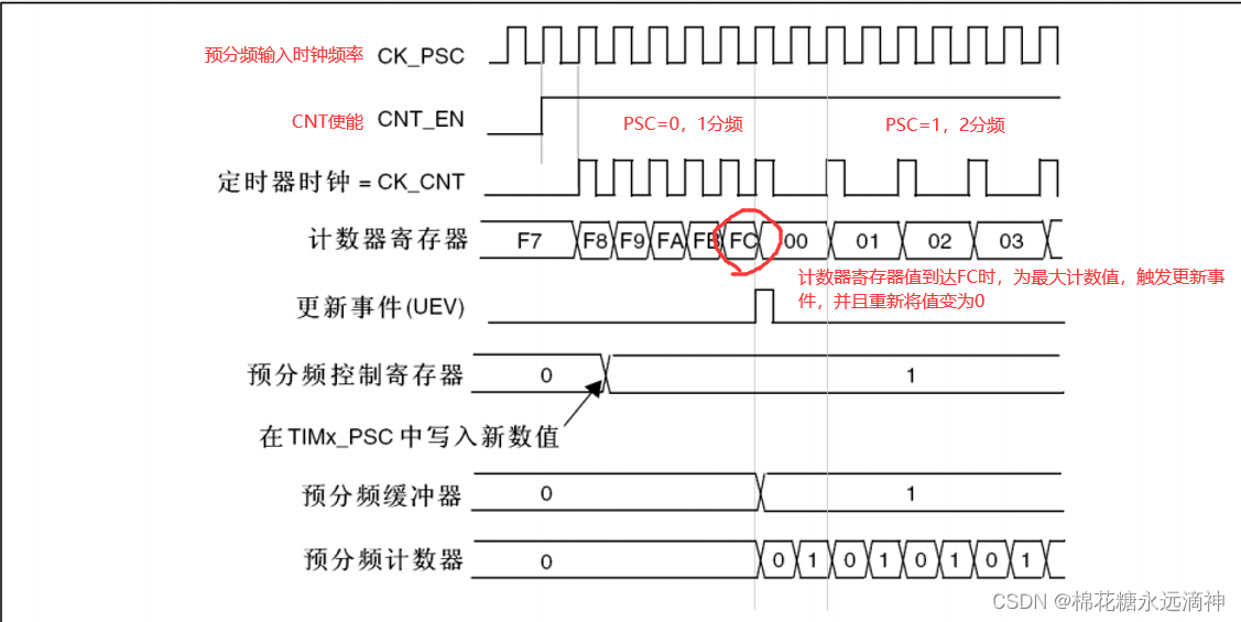
CK_PSC becomes CK_CNT after frequency division by the prescaler (PSC), and finally loses to CNT. The CNT is reloaded with the initialization value at the end of counting cycles.
Note that the frequency divider PSC here can divide the frequency by writing its value, such as writing 0 to it, that is, no frequency division, writing 1, that is, two frequency division, writing 2, that is, three frequency division, and so on. That is, the actual frequency division = prescaler + 1. Up to 65535 frequency divisions can be performed.
Automatic reload register ARR: The CNT register is used for counting, and the ARR register is used to set the initial value and automatic reload value of the counter. When CNT counts to the value set by ARR, the timer will trigger an interrupt or generate an output signal, and then automatically reload the value of ARR to make the counter restart counting. By repeating this process continuously, the function of the timer can be realized.
3. General timer structure
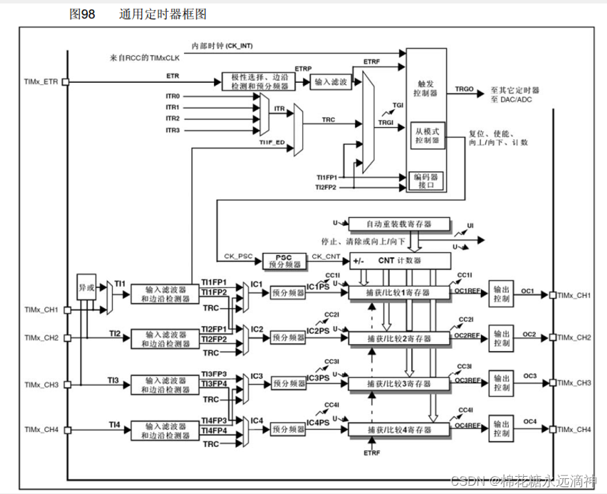
The structure of the general-purpose timer can be roughly divided into three parts, namely the input clock part , the core counter part and the input capture part .
(1) Input clock
The clock of the general-purpose timer can come from the AHB bus clock (CK_INT), which is 72MHZ , or from the external clock input pin (TIMx_ETR) , or from other timers with clock output function (ITRx) , or Can come from compare capture channel input (TIMx_CHx) .
These input clock signals become the CK_PSC clock after various settings such as filtering and frequency division, and are output to the core counter part. In addition, these complex clock sources can also be output as TRGO to other peripherals such as timers, ADC and DAC.
(2) Core counter The general-
purpose timer supports three counting methods: up-counting, down-counting, and center-aligned.
Up-counting (Up-Counting) means that the counter counts up from 0 until it reaches the maximum value of the counter, and then restarts from 0. Start counting up. This counting method is often used in occasions such as timers and timers.
Down-counting (Down-Counting) means that the counter counts down from the maximum value until the counter value is 0, and then counts down from the maximum value again. This counting method is often used in countdown, counter and other occasions.
Center-Aligned means that the counting direction of the counter can be either up counting or down counting, and the counting value and counting period of the counter are both even numbers.
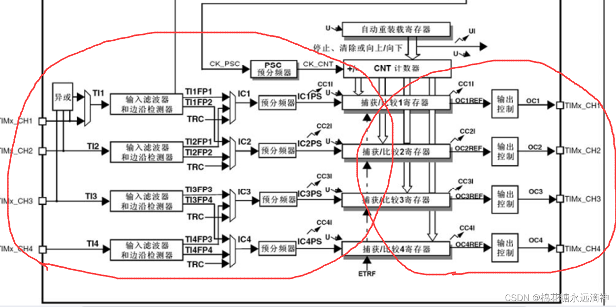
(3) Input capture and output comparison
The general-purpose timer has four groups of comparison capture channels, each group of comparison capture channels can input pulses from dedicated pins, and can also output waveforms to pins, that is, comparison capture channels support input and output model. The input of each channel of the comparison capture register supports operations such as filtering, frequency division, and edge detection, and supports mutual triggering between channels, and can also provide clocks for the core counter CNT. Each compare capture channel has a set of compare capture registers (CHxCVR), which support comparison with the main counter (CNT) and output pulses.
4. Timer interrupt structure
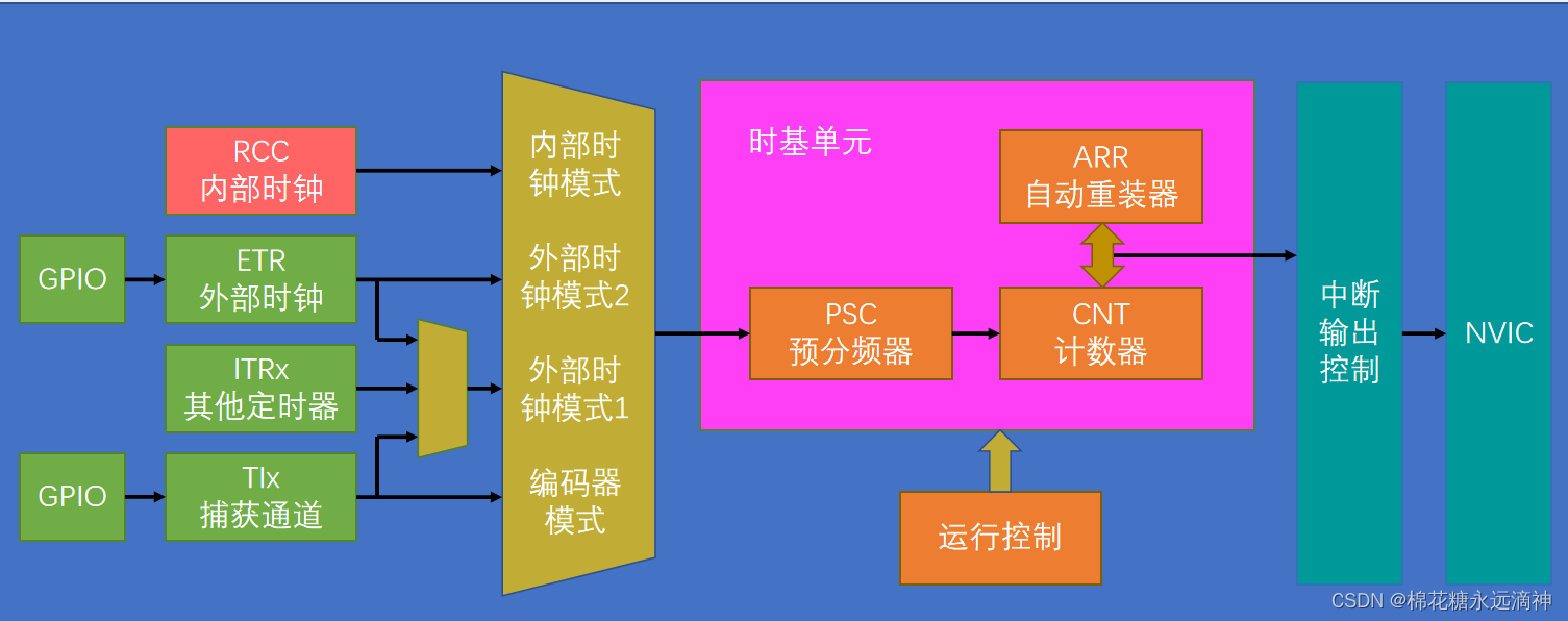
The left side is the input clock part, the core is the time base unit, that is, PSC, CNT and ARR, the operation control refers to the counting method, such as counting up and down, and then the CNT counts to generate an interrupt, and the output control is given to the NVIC interrupt line.
Counter counting frequency: CK_CNT = CK_PSC / (PSC + 1)
Counter overflow frequency: CK_CNT_OV = CK_CNT / (ARR + 1)
= CK_PSC / (PSC + 1) / (ARR + 1)
Counter overflow frequency refers to the frequency of counter overflow , that is, the frequency at which the counter restarts counting from 0 after overflowing from the maximum value. For example, if the clock frequency of a counter is 1MHz, the value of the auto-reload register is 999 (that is, the maximum value of the counter is 999), the clock frequency of the counter clock prescaler is 10MHz, and the frequency division factor is 9, then the counter's The overflow frequency is:
CK_CNT_OV = 1MHz / (999 + 1) = 1kHz
5. Doubt
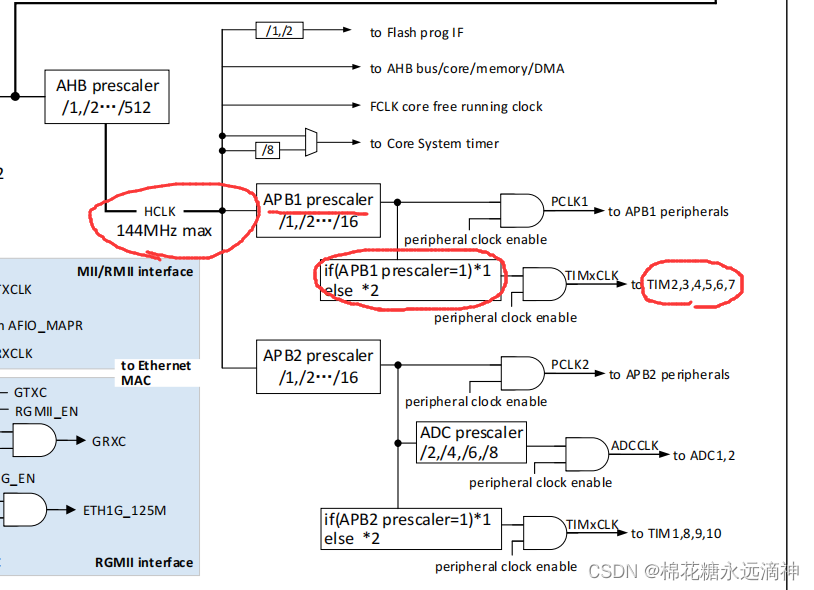
It can be seen here that the system clock is 144MHz, TIM2, 3, 4, 5, 6, and 7 are mounted on the APB1 bus, so what does the red box in the middle mean?
If the division factor of the APB1 bus prescaler is 1, then the clock frequency used by the timer is the clock frequency of the APB1 bus, otherwise the clock frequency used by the timer is the clock frequency of the APB1 bus divided by 2. When the prescaler coefficient of APB1 is 2, the system clock output is 72MHZ, but it needs to be multiplied by 2 again, and it becomes 144MHZ again.
So, for timers, their clock frequency is the system clock frequency.
6. Output compare function
The compare output mode is one of the basic functions of the timer. The principle of the comparison output mode is to output a specific change or waveform when the value of the core counter (CNT) is consistent with the value of the comparison capture register. The OCxM field (in R16_TIMx_CHCTLRx) and the CCxP bits (in R16_TIMx_CCER) determine whether the output is a definite high or low level or a level toggle. The CCxIF bit will also be set when a compare coincidence event occurs. If the CCxIE bit is preset, an interrupt will be generated; if the CCxDE bit is preset, a DMA request will be generated.
The steps to configure the comparison output mode are as follows:
1) Configure the clock source and auto-reload value of the core counter (CNT);
2) Set the count value to be compared to the comparison capture register (R16_TIMx_CHxCVR);
3) If necessary, generate interrupt, set CCxIE bit;
4) keep OCxPE to 0, disable preload register of compare capture register;
5) set output mode, set OCxM field and CCxP bit;
6) enable output, set CCxE bit;
7) set The CEN bit starts the timer;
PWM output mode
PWM output mode is one of the basic functions of the timer. The most common PWM output mode is to use the reload value to determine the PWM frequency, and use the capture compare register to determine the duty cycle. Set the OCxM field to 110b or 111b to use PWM mode 1 or 2, set the OCxPE bit to enable the preload register, and finally set the ARPE bit to enable the automatic reload of the preload register. When an update event occurs, the value of the preload register can be sent to the shadow register, so before the core counter starts counting, it is necessary to set the UG bit to initialize all registers. In PWM mode, the core counter and compare capture register are always comparing, and the timer can output edge-aligned or center-aligned PWM signals according to the CMS bit.
Edge
alignment When edge alignment is used, the core counter counts up or down. In PWM mode 1, when the value of the core counter is greater than the compare capture register, OCxREF rises to high; when the value of the core counter is less than the compare capture register ( For example, when the core counter increments to the value of R16_TIMx_ATRLR and returns to all 0s), OCxREF falls to low.
Center Alignment
When the center alignment mode is used, the core counter runs in the mode of up-counting and down-counting alternately, and OCxREF jumps up and down when the values of the core counter and the comparison capture register are consistent. However, the timing of setting the comparison flag is different in the three center alignment modes. When using center-aligned mode, it is best to generate a software update flag (set the UG
bit) before starting the core counters.
Summarize
Here is a study on the general-purpose timer. I pay more attention to the PWM output function, which should be a very common function of TIM.