[ Written in the front ] I also wrote a few sharing articles for everyone before the May 1st holiday. I hope that my articles can bring some help to you who are preparing for the soft exam network administrator exam. May 27th is also the National Computer Software The examination time is unified, so there is no need to go to various places to find information and codes.
Immediately afterwards, I will share some of the materials I have compiled with you. It is mainly aimed at the knowledge points of the network architecture of the primary data of the national soft exam network administrators: osi seven-layer model, the concept of throughput bandwidth delay, TCP/IP system structure and concept.
Table of contents
1. Basic concepts of network
1.1 Composition of the network
From the perspective of the functions of the components of the computer network, each component mainly completes two functions, namely, network communication and resource sharing. The collection of devices and their software that implement network communication functions in a computer network is called a network communication subnet, and the collection of devices and their software that implement resource sharing functions in a network is called a resource subnet.
Resource subnet: composed of network servers, workstations, shared printers and other devices and related software.
Communication subnet: refers to the collection of devices and software that implement network communication functions in the network. Communication equipment, network communication protocols, communication control software, etc. belong to the communication subnet, which is the inner layer of the network and is responsible for the transmission of information. Mainly provide users with data transmission, transfer, processing, transformation, etc.
1.2 Performance parameters of the network
Computer network performance parameters include: speed, bandwidth, throughput, delay, channel utilization, etc.
1.2.1. Rate
The rate in network technology refers to the rate at which a host connected to a computer network transmits data on a digital channel, which is also called data rate or bit rate. Speed is the most important performance index in computer network. The unit of rate is bit/s or bps (bits per second).
1.2.2. Bandwidth
"Bandwidth" has the following two different meanings. (1) Bandwidth originally refers to the frequency bandwidth of a certain signal. The bandwidth of a signal refers to the frequency range occupied by various frequency components contained in the signal. For example, the standard bandwidth of a telephone signal transmitted on a traditional communication line is 3.1 kHz (from 300 Hz to 3.4 kHz, the frequency range of the main components of speech). The unit of bandwidth in this sense is hertz (or kilohertz, megahertz, gigahertz, etc.). (2) In a computer network, bandwidth is used to represent the ability of the communication line of the network to transmit data, so the network bandwidth represents the "highest data rate" that can pass from one point to another point in the network within a unit of time. The "bandwidth" generally mentioned here refers to this meaning. The unit of bandwidth in this sense is "bit per second", denoted as bit/s.
1.2.3. Throughput
Throughput represents the amount of data passing through a network (or channel, interface) per unit time. Throughput is more often used as a measure of real-world networks to know how much data is actually going through the network. Obviously, the throughput is limited by the bandwidth of the network or the rated rate of the network. For example, for a 100Mbit/s Ethernet, its rated rate is 100Mbit/s, then this value is also the absolute upper limit of the throughput of the Ethernet. Therefore, for 100Mbit/s Ethernet, its typical throughput may only be 70Mbit/so sometimes the throughput can also be expressed by the number of bytes or frames transmitted per second.
1.2.4. Latency
Latency is the time it takes for data to travel from one end of a network (or link) to the other. The delay in the network is composed of transmission delay, propagation delay, processing delay and queuing delay. (1) Transmission delay The transmission delay is the time required for the host or router to send a data frame, that is, the time required to send the last bit of the frame from the first bit of the data frame. Transmission delay may also be referred to as sending delay. Transmission delay = data frame length (b) / sending rate (b/s) o (2) Propagation delay Propagation delay is the time it takes for electromagnetic waves to propagate a certain distance in the channel. Propagation delay = channel length (m)/propagation rate of electromagnetic waves on the channel (m/s). Note: The propagation rate of electromagnetic waves in free space is the speed of light, that is, the propagation rate of 3.0X10⁵km/so electromagnetic waves in network transmission media is lower than that in free space, and the propagation rate in copper wire cables is about 2.3Xl() 5km/s , The propagation rate in the optical fiber is about 2.OX105km/so (3) Processing time delay The host or router will spend a certain amount of time processing when receiving the packet, which results in a processing time delay. (4) Queuing delay Queuing delay: When a packet is transmitted through the network, it will pass through many routers. Packets are queued in input queues for processing before entering the router. After the router determines the forwarding interface, it must queue up in the output queue and wait for forwarding. This creates a queuing delay. In this way, the total delay experienced by data in the network is: total delay = sending delay + propagation delay + processing delay + queuing delay.
1.2.5 Channel utilization
Channel utilization indicates how many percent of the time a channel is used
1.3 Concept of protocol
Multiple computer systems in different geographical locations interconnected through communication channels and devices must have a common language in order to enable them to work together to achieve information exchange and resource sharing. What, how, and when to communicate must follow certain mutually acceptable rules. A set of rules, standards, or conventions established for the exchange of data in a computer network. A protocol always refers to a certain layer of protocol. To be precise, it is a collection of relevant communication rules and conventions formulated for communication between equivalent entities. Three elements of a network protocol:
Semantics: Involves control information for coordination and error handling.
Syntax: Involves the format, coding and signal level of data and control information.
Timing: involves speed matching and sequencing, etc.
2. OSI seven-layer model
2.1 Functions of each layer
The osi architecture defines a seven-layer model for inter-process communication and as a framework to coordinate the formulation of standards for each layer; the service definition of OSI describes the services provided by each layer, as well as the inter-layer The abstract interface and service primitives used for interaction; the protocol specifications of each layer of OSI precisely define what kind of control information should be sent and what process should be used to interpret the control information. The mnemonic method of y substructure is shown in Figure 6-1 below: 0SI/RM divides the system into seven layers, which are Physical Layer (Physical Layer, PHL) and Data Link Layer (Data Link Layer, DLL) from bottom to top. ), Network Layer (Network Layer, NL) > Transport Layer (Transport Layer, TL) > Session Layer (Session Layer, SL) > Presentation Layer (Presentation Layer, PL) and Application Layer (Application Layer, AL), as shown in Figure 3T shown.
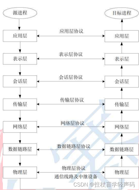
2.1.1. Physical layer
Provides bitstream transmission between adjacent devices. It uses the physical communication medium to provide a physical connection for the upper layer (data link layer), and transparently transmits the bit stream through the physical connection. The so-called transparent transmission means that the bit stream transmitted through the actual circuit does not change, and any combination of bit streams can be transmitted on this circuit, and the physical person does not know the meaning of the bit. What the physical layer needs to consider is how to send "0" and "1" and how to identify them at the receiving end.
2.1.2. Data Link Layer
Responsible for transmitting frame-based data without error on the line between two adjacent nodes. Each frame includes certain data and necessary control information. When the receiving point receives an error in the data, it must notify the sender to resend until This frame arrives at the receiving node without error. The data link layer is to turn an actual link that may be wrong into a link that makes the network layer seem to be error-free.
2.1.3. Network layer
Two computers communicating in the network may pass through many nodes and links, and may also pass through several communication subnets. The transmission unit of network layer data is a packet. The task of the network layer is to select an appropriate route so that the packets sent by the transport layer of the sending station can correctly find the destination station according to the address and deliver it to the transport layer of the destination station. This is the addressing function of the network layer.
2.1.4. Transport layer
The task is to make optimal use of network resources according to the characteristics of the communication subnet, and to establish a transmission connection between the session layers of two end systems in a reliable and economical way, and to transmit messages transparently. The transport layer provides a reliable end-to-end service to the upper layer, so that the session layer does not know the details of the data communication below the transport layer.
2.1.5. Session layer
Although the session layer does not participate in specific data transmission, it manages the data. It provides a set of session facilities for the presentation processes that cooperate with each other, organizes and synchronizes their session activities, and manages their data exchange process.
2.1.6. Presentation layer
The sixth eye in the Open Systems Interconnection (OSI) model provides information representation to the application process so that systems with different representations can communicate. The presentation layer is also responsible for data encryption and compression.
2.1.7. Application layer
At the highest layer in the Open Systems Interconnection (0SI) model, services are provided for applications to ensure communication. The main purpose is to provide an interface to software so that software programs can use network services.
2.2 SAP concept
Encapsulation means that the network node packs the data to be transmitted with a specific protocol and then transmits it. Most protocols implement encapsulation by adding an encapsulation header before the original data, and some protocols also add an encapsulation trailer after the data, and the original data becomes the payload. On the sending side, each layer of the osi seven-layer model encapsulates the upper layer data to ensure that the data can be transmitted to the destination without error; on the receiving side, each layer decapsulates the encapsulated data of this layer, and Passed to the upper layer so that the data can be understood by the upper layer.
(N) layer entities provide services to (N+1) layer entities, and (N+1) layer entities request services from (N) layer entities. Conceptually, this is achieved through It is implemented by the service access point (N) SAP on the interface of the ) layer. (N)SAP is an access tool consisting of a set of service elements and abstract operations and invoked at that point by (N+1) entities. We collectively call those (N) entities that provide (N) services in the (N) layer (N) service providers; and call (N+1) entities that call (N) services as (N) service users. As shown in Figure 3-2
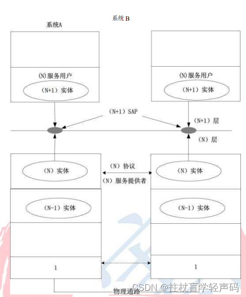
Figure 3-2 Service access point SAP In the OSI environment, information transmission occurs between peer entities that have established connections at the first layer, and can also occur between entities in adjacent subsystems of the same open system. Therefore, different types of data units are used to represent information of such different transmission modes. (N) Protocol Data Unit (N) PDU: A unit for exchanging information between peer (N) entities of the same layer that have established a connection. (N) Service Data Unit (N) SDU: The exchange of information from adjacent two-layer entities is the exchange of information between the service provider and the service user. (N) Interface Data Unit (N) IDU: On the (N+l)/f (N) layer boundary, the information exchanged between (N+1) entity and (N) entity is commonly referred to as (N) interface data
3.TCP/IP Architecture
3.1 Functions of each layer
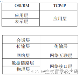
osi is a purely theoretical framework concept proposed by the International Organization for Standardization to realize device interconnection. Because the OSI network model standard is relatively strict and too complicated, and it was introduced relatively late, there is currently no network fully implemented according to the OSI model. On the other hand, with the rapid development of the Internet, the TCP/IP architecture has become popular, and it is the most widely used network model in our practice. The TCP/IP protocol family is also a hierarchical architecture, which is divided into 5 layers. The underlying physical layer and data link layer only need to support the packet transmission of the IP layer, so they are treated as the network interface layer. From the perspective of hierarchical structure, the architecture model of TCP/IP is shown in Table 3-1. Table 3-1 TCP/IP protocol layer relationship
3.2 Layers of protocols
The functions of each layer of the TCP/IP protocol family are briefly described as follows: Network interface layer: Provides sending and receiving of IP datagrams. The protocol used in this layer is the inherent protocol of each communication subnet itself. For example, the 802.3 protocol of the Ethernet, the 802.5 protocol of the token ring network, and the X. 25 protocol of the packet interactive network.
Network layer: Provides packet transmission between computers.
(1) Packet generation of high-level data;
(2) Packet assembly of low-level datagrams;
(3) Dealing with issues such as routing, flow control, and congestion. The IP protocol provides a unified address format and IP data packet format to eliminate the differences of each communication subnet, thus providing a transparent channel for the information sender and receiver. Transport layer: Provides communication between applications.
(1) Format information flow;
(2) Provide reliable transmission. The TCP protocol provides connection-oriented reliable byte stream transmission; the UDP protocol provides connectionless unreliable packet transmission. Application layer: Provides commonly used applications.
Application layer protocols include HTTP, FTP, SMTP, POP3, Telnet, DNS, SNMP, RIP, DHCP, etc. The transport layer bearer protocols of HTTP, FTP, SMTP, POP3, and Telnet are based on TCP. The transport layer bearer protocols of DNS, SNMP, RIP, and DHCP are for UDP.
4. End credits easter eggs
Dedicated to creating a masterpiece, I would like to solve your confusion. If you are lucky, I hope you will be on the list to help out. Thank you very much! Click here for the entrance of
Huangbang