The job of a digital filter is to filter out signals that are not of interest, leaving the desired signal. Digital filters can be divided into infinite impulse response (IIR) digital filters and finite impulse response (FIR) digital filters, both of which have their own advantages and disadvantages. Among them, FIR digital filters are widely used because of their good linear phase characteristics. Application, linear phase means that the relative phase relationship of each frequency component in the signal does not change, that is, the delay time of each frequency component after the signal passes through a filter with linear phase characteristics is the same, and the IIR digital filter achieves the same performance index. The required order is smaller and the cost is lower, but the phase is nonlinear, so many aspects need to be considered when selecting the filter. In occasions that are not sensitive to phase requirements, such as voice communication, it is more appropriate to choose IIR, which can Give full play to its cost-effective features; in occasions with high linear phase requirements, such as radar, image processing, data transmission and other systems that carry information in waveforms, FIR digital filters need to be used.
There are many methods in MATLAB to implement FIR digital filtering. For example, use the fir1 function to first obtain the filter coefficient h, and then use the filter/conv function to convolve the obtained coefficient h with the filter input signal. This paper mainly introduces a more flexible and intuitive graphical filter design method, that is, using the Filter Designer toolbox that comes with MATLAB to complete the design of the FIR digital filter by setting relevant parameters, and the coe file generated by the filter coefficients can also be used for FPGA implementation. The way to open it is: find "APP" in the MATLAB toolbar, and select Filter Designer from the drop-down bar, as shown in the figure below.

Then set the relevant parameters:
Response Type: Select the type of filter: low pass, high pass, band pass, band stop, etc.
Design Method: There are many FIR filter design methods, the most commonly used are window function design method (Window), equiripple design method (Equiripple) and least squares method (Least-Squares). Among them, the window function design method is mainly explained in the school classroom. When it comes to FIR filters, hamming and kaiser windows will definitely come to mind, but they are rarely used in practical applications, because if the window function design method is used, the desired frequency response can be achieved. , compared with other methods, the order will often be more; and the window function design method generally only designs the filter with reference to the passband wp, the rejection band ws and the ideal gain, but the ripple of the passband and the rejection band in practical applications also needs to be considered Yes, in this case, the equi-ripple design method is very applicable.
Filter Order: Set the order of the filter. This option directly affects the performance of the filter. The higher the order, the better the performance, but correspondingly more resources are consumed in FPGA implementation. There are 2 options in this setting: Specify order and Minimum order. Specify order is the order of the filter determined by the user himself, and its value is equal to the filter order -1. Minimum order is to let the tool automatically determine the desired frequency corresponding to the order The minimum order required.
Frequency Specification: Set the parameters of the frequency response, including sampling frequency Fs, passband frequency Fpass, and stopband frequency Fstop. The passband frequency can be understood as allowing frequencies less than Fpass to pass, and the stopband frequency can be understood as allowing frequencies greater than Fstop to be suppressed. .
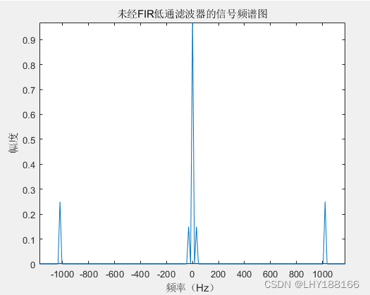
This article takes the design of a FIR low-pass filter to filter out the 1020Hz high-frequency component in a signal containing three frequency components of DC, 30Hz, and 1020Hz (the spectrum diagram is shown in the figure below) as an example, and introduces the filter parameter setting method. (For the method of drawing a spectrogram, see the previous article - FFT of signal processing).
The parameter settings are shown in the figure below.
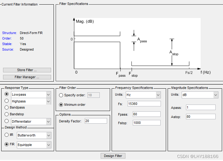
Select low-pass for Response Type, select FIR and other ripple design methods for Design Method, select Minimum order for Filter Order, and set the sampling rate to 15360Hz in Frequency Specification. In order not to attenuate the low-frequency component of 30Hz as much as possible, the passband frequency is set to 60Hz. The component plays a better attenuation effect, and the stopband frequency is set to 1000Hz.
After the parameter setting is complete, click "Design Filter", and you can see the designed filter order is 41 and the amplitude-frequency response curve of the filter, and you can observe the attenuation of different frequency components, as shown in the figure below.
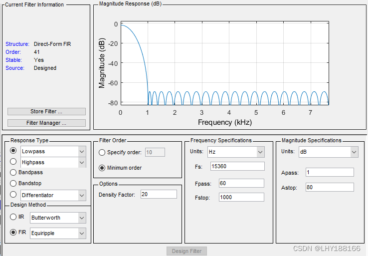
From the amplitude-frequency response curve in the above figure, it can be seen that there is an attenuation of about 60dB at 1020Hz. According to -60=-20lg (amplitude before attenuation/amplitude after attenuation), the attenuation amplitude is the thousandth of the attenuation before attenuation One, that is, the frequency component of 1020Hz can be better filtered out. Matlab code can be generated by following the steps shown in the figure below.

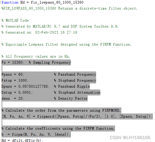
Copy and paste the shaded part of the generated code to the main program, and then use conv(x,b,'same') to get the signal after the FIR low-pass filter, and its spectrum is shown in the figure below, where x is the input signal to the filter.
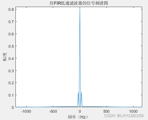
It can be seen from the figure that the high-frequency component of 1020Hz is filtered, leaving only the DC component and the low-frequency component of 30Hz.
References: https://blog.csdn.net/weixin_28951059/article/details/112188261
References: https://blog.csdn.net/s09094031/article/details/83755663