Article directory
foreword
1. Introduction to SPI
1. What is SPI
SPI, is the abbreviation of English Serial Peripheral interface, as the name suggests is the serial peripheral interface. It was first defined by Motorola on its MC68HCXX series processors. The SPI interface is mainly used between EEPROM, FLASH, real-time clock, AD converter, and digital signal processor and digital signal decoder. SPI,是一种高速的,全双工,同步的通信总线, and only occupy four wires on the pins of the chip, which saves the pins of the chip, and at the same time saves space for the layout of the PCB and provides convenience. It is precisely because of this easy-to-use feature that more and more Advanced chips integrate this communication protocol, such as the MSP430 microcontroller series processors.
2. Characteristics of SPI
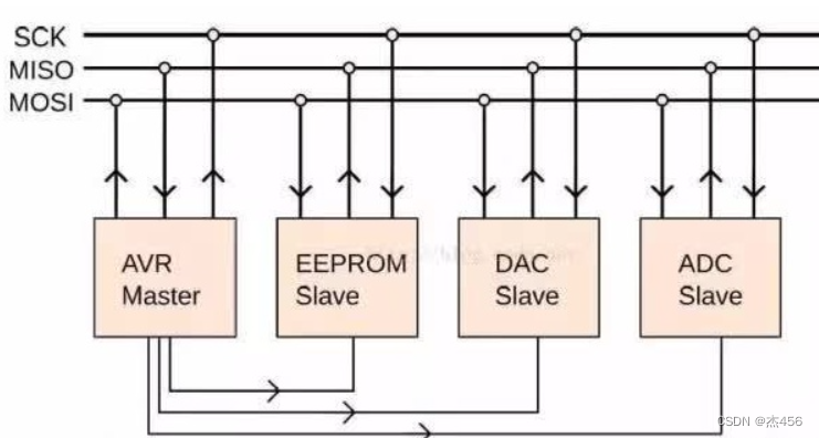
SPIThe bus consists of 4 logic lines
- MISO: Master input slave output Master input, slave output (data from the slave).
- MOSI: Master output slave input Master output, slave input (data from the master).
- SCLK: Serial Clock Serial clock signal, generated by the master and sent to the slave.
- SS: Slave Select Chip select signal, sent by the master to control which slave to communicate with, usually a low-level active signal.
3. Advantages of SPI
- It supports full duplex communication
- communication is very simple
- The data transfer rate is fast
缺点:There is no specified flow control, and there is no response mechanism to confirm whether the data is received, so compared with the IIC bus protocol, there are certain defects in data reliability.
4. Characteristics of SPI communication
-
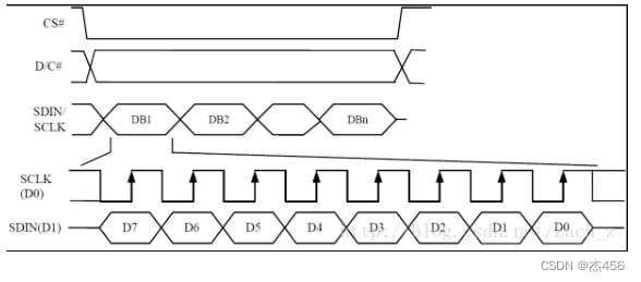
The master device will generate the corresponding clock pulse (Clock Pulse) according to the data to be exchanged in the synchronous way (Synchronous), the clock pulse constitutes the clock signal (Clock Signal), and the clock signal passes through the clock polarity (CPOL) and the clock phase (CPHA) controls when data is exchanged between two SPI devices and when the received data is sampled to ensure that data is transmitted synchronously between the two devices.
-
The master-slave mode (Master-Slave) control method
SPI stipulates that the communication between two SPI devices must be controlled by the master device (Master) and the slave device (Slave). A Master device can control multiple Slave devices by providing Clock and chip selection (Slave Select) to the Slave device. The SPI protocol also stipulates that the Clock of the Slave device is provided to the Slave device by the Master device through the SCK pin, and the Slave device itself cannot generate Or control the Clock, without the Clock, the Slave device cannot work normally. -
Data Exchanges
The reason why data transmission between SPI devices is also called data exchange is because the SPI protocol stipulates that an SPI device cannot only act as a "Transmitter" or "Receiver" in the process of data communication. (Receiver)". In each Clock period, the SPI device will send and receive a bit-sized data (regardless of whether the master device is good or the slave device), which means that the device has a bit-sized data exchanged. If a Slave device wants to be able to receive the control signal sent by the Master, it must be able to be accessed (Access) by the Master device before that. Therefore, the Master device must first select the Slave device through the SS/CS pin, and select the Slave device to be accessed. During data transmission, each received data must be sampled before the next data transmission. If the previously received data is not read, the data that has been received may be discarded, resulting in the final failure of the SPI physical module. Therefore, in the program, the data in the SPI device is generally read after the SPI transmits the data, even if the data (Dummy Data) is useless in our program (although the reading immediately after sending is meaningless , but still need to be read from the register).
Two, oled display name
1. A brief introduction to oled
This study uses the oled screen of the four-wire spi to display and learn the SPI protocol.
- The pins are defined as follows.
| pin | pin definition |
|---|---|
| GND | land |
| VCC | Power supply, 3.3~5v |
| D0 | 4-wire ISP interface mode: clock line (CLK) |
| D1 | 4-wire ISP interface mode: serial data line (MOSI) |
| RES | 4-wire ISP interface mode: command/data flag (RET reset) |
| DC | command/data flag |
| CS | OLED Chip Select |
- Timing diagram
2. Download and use font-taking software
The liquid crystal display module of the single-chip microcomputer is displayed in the form of a dot matrix. When displaying Chinese characters, the font will be used. The font is the corresponding code when the Chinese character is displayed on the LCD screen. If we come by ourselves, it will be very troublesome. We can use fonts to obtain software, which is very convenient, just use the obtained fonts.
Software download link : http://www.lcdwiki.com/zh/0.96inch_SPI_OLED_Module
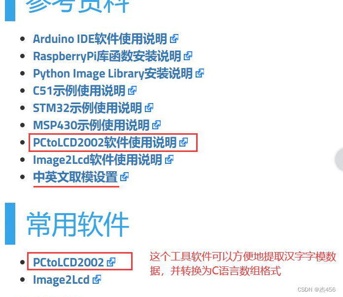
You can go here to download it yourself.
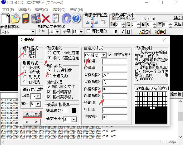
- Font software related settings
3. oled initialization code
void OLED_Init_GPIO(void)
{


	GPIO_InitTypeDef  GPIO_InitStructure;
 	RCC_APB2PeriphClockCmd(RCC_APB2Periph_GPIOB, ENABLE);	 //使能B端口时钟
	GPIO_InitStructure.GPIO_Pin = GPIO_Pin_10|GPIO_Pin_11|GPIO_Pin_12|GPIO_Pin_13|GPIO_Pin_15;	//GPIOB10,11,12,13,15
 	GPIO_InitStructure.GPIO_Mode = GPIO_Mode_Out_PP; 		 //推挽输出
	GPIO_InitStructure.GPIO_Speed = GPIO_Speed_50MHz;//速度50MHz
 	GPIO_Init(GPIOB, &GPIO_InitStructure);	  //初始化GPIOB10、11、12、13、15
 	GPIO_SetBits(GPIOB,GPIO_Pin_10|GPIO_Pin_11|GPIO_Pin_12|GPIO_Pin_13|GPIO_Pin_15);
}
void OLED_Init(void)
{


 	OLED_Init_GPIO(); //初始化GPIO
 	delay_ms(200);
	OLED_Reset();     //复位OLED

/**************初始化SSD1306*****************/
	OLED_WR_Byte(0xAE,OLED_CMD); /*display off*/
	OLED_WR_Byte(0x00,OLED_CMD); /*set lower column address*/
	OLED_WR_Byte(0x10,OLED_CMD); /*set higher column address*/
	OLED_WR_Byte(0x40,OLED_CMD); /*set display start line*/
	OLED_WR_Byte(0xB0,OLED_CMD); /*set page address*/
	OLED_WR_Byte(0x81,OLED_CMD); /*contract control*/
	OLED_WR_Byte(0xFF,OLED_CMD); /*128*/
	OLED_WR_Byte(0xA1,OLED_CMD); /*set segment remap*/
	OLED_WR_Byte(0xA6,OLED_CMD); /*normal / reverse*/
	OLED_WR_Byte(0xA8,OLED_CMD); /*multiplex ratio*/
	OLED_WR_Byte(0x3F,OLED_CMD); /*duty = 1/64*/
	OLED_WR_Byte(0xC8,OLED_CMD); /*Com scan direction*/
	OLED_WR_Byte(0xD3,OLED_CMD); /*set display offset*/
	OLED_WR_Byte(0x00,OLED_CMD);
	OLED_WR_Byte(0xD5,OLED_CMD); /*set osc division*/
	OLED_WR_Byte(0x80,OLED_CMD);
	OLED_WR_Byte(0xD9,OLED_CMD); /*set pre-charge period*/
	OLED_WR_Byte(0XF1,OLED_CMD);
	OLED_WR_Byte(0xDA,OLED_CMD); /*set COM pins*/
	OLED_WR_Byte(0x12,OLED_CMD);
	OLED_WR_Byte(0xDB,OLED_CMD); /*set vcomh*/
	OLED_WR_Byte(0x30,OLED_CMD);
	OLED_WR_Byte(0x8D,OLED_CMD); /*set charge pump disable*/
	OLED_WR_Byte(0x14,OLED_CMD);
	OLED_WR_Byte(0xAF,OLED_CMD); /*display ON*/
}
4. oled display character effect
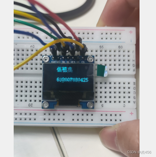
It can be found that the character display effect is very successful, and the name and student number are displayed
3. OLED echoes the temperature and humidity collected by the temperature and humidity sensor
This is based on my last blog, which is a display of the data collected by the temperature and humidity sensor on the oled. I will not introduce the collection of temperature and humidity here. If you are interested, you can go to my last blog. Here we will focus on how to display temperature and humidity on oled.
- Related display codes. The code here is a call to the oled library written by the manufacturer, which can be downloaded from the above modulo software information
void TEST_MainPage(u32 Tem,u32 Hum)//这里传进来的Tem为温度,Hum为湿度
{


	GUI_ShowCHinese(10,0,16,"温度",1);
	GUI_ShowString(40,0,":",16,1);
	GUI_ShowCHinese1(10,20,16,"湿度",1);
	GUI_ShowString(40,20,":",16,1);
	GUI_ShowNum(50,0,(u32 *)(Tem/10),2,16,1);
	GUI_ShowString(68,0,".",16,1);
	GUI_ShowNum(75,0,(u32 *)(Tem%10),1,16,1);
	GUI_ShowNum(50,20,(u32 *)(Hum/10),2,16,1);
	GUI_ShowString(68,20,".",16,1);
	GUI_ShowNum(75,20,(u32 *)(Hum%10),1,16,1);
	GUI_ShowString(85,0,"*c",16,1);
	GUI_ShowString(85,20,"%",16,1);
	delay_ms(1500);
	delay_ms(1500);
}
- Actual display effect display
Four, oled realizes the scrolling of text
Regarding the scrolling of the text, the hardware refresh program given by the manufacturer is used, not the simulated program written by myself. During the actual test process, you will find that the simulation program you wrote is not very smooth, very stuck, and sometimes even Lost words. Therefore, it is recommended to use the hardware refresh program provided by the manufacturer, which will be very smooth.
int main(void)
{


	delay_init();
	NVIC_Configuration();
	OLED_Init();
	OLED_Clear(0);
	OLED_WR_Byte(0x2E,OLED_CMD);
	OLED_WR_Byte(0x26,OLED_CMD);
	OLED_WR_Byte(0x00,OLED_CMD);
	OLED_WR_Byte(0x00,OLED_CMD);
	OLED_WR_Byte(0x07,OLED_CMD);
	OLED_WR_Byte(0x07,OLED_CMD);
	OLED_WR_Byte(0x00,OLED_CMD);
	OLED_WR_Byte(0xFF,OLED_CMD);
	TEST_MainPage(0,0);
	OLED_WR_Byte(0x2F,OLED_CMD);
	while(1);
}
- The actual effect realized in kind
Summarize
In the actual learning process, I learned a lot by looking at the source code given by the manufacturer, that is, the oled display library that the manufacturer has written. Although many of them were not written by myself, by reading their code, not only in code style but also in principle In terms of realization, it has been very helpful to me. During the learning process, I also encountered many problems, such as oled cannot display characters, etc. After subsequent investigations, I found that it was caused by my lack of care. It is not a big problem, but I only have a preliminary understanding of spi. Not very familiar with it, still need to continue to work hard!