STM32 control stepper motor: ULN2003 driver/stepper motor driver based on timer interrupt
Revise
2023.04.24 Modifications: The following program has been improved, and some content in the working principle has been added.
I read the question pointed out by a friend in the comment area, and then I made some small changes to the working principle and program in the article (modified positions are: 1, 1 2; 3, 1; 5), so that friends who have previously collected it can refer to it , the program source files are also re-uploaded. The pulses required for one circle in this article are calculated as 4096 pulses, but in fact, my personal test is 2048 pulses, and the output of the driver is normal when measured with an oscilloscope (1, 2). It is not clear why . In order not to mislead other later friends, let me explain here first. If anyone knows the reason, criticism is welcome.
1. ULN2003 driver
1. Working principle
The figure below is the schematic diagram of the ULN2003 driver.
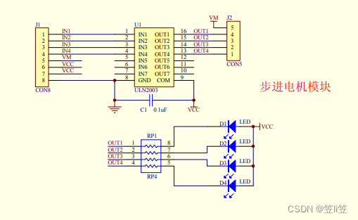
The principle of this driver is the working principle of the stepper motor. This article introduces: STM32 control stepper motor: working principle and library function (standard library) / HAL library control program (updated from time to time)
through one after another The pin drives the 4 phases of the motor to make the stepper motor rotate. When the driver input is low level, the corresponding output pin outputs high level. Conversely, when the input is high level, the output is low level. Therefore, when some pins are output as high level, the corresponding pins should be set as low level, and other pins as high level.
2. Calculation of the step angle and the number of steps required for a circle
The 4-phase 5-wire stepper motor used in this article has a step angle of 5.625/64, so the stepper motor needs to take 360°/step angle steps per revolution, that is, (360/5.625)*64 = 4096 steps .
Although the calculation is 4096 pulses per circle, in fact, when I use it, the motor rotates with 2048 pulses per circle, so I used an oscilloscope to test whether there is any problem with the program.
Indicated in white circles as shown below:


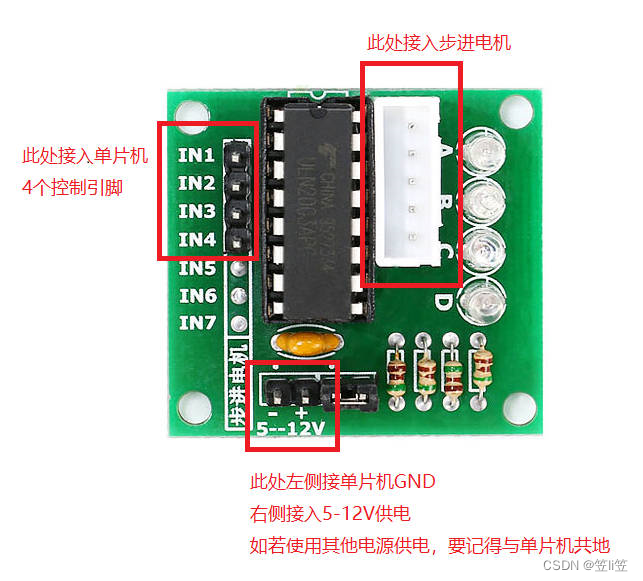
2. Hardware connection
As shown in the picture, remember to share the ground. The 4 control pins are defined and referenced in the .h and .c files of the program below.
3. STM32F103 timer interrupt control stepper motor program
The effect of this program is to rotate forward for 1 week and then reverse 1 week to return to the origin. The procedure is as follows.
1. .c file
The following is the motor.c file driven by the stepper motor :
#include "motor.h"

//num用于对引脚的索引,j用于计算步数,fx为电机旋转方向
unsigned short int num=0,j,fx;

void motor_GPIO_Init(void)
{


 GPIO_InitTypeDef  GPIO_InitStructure;

 RCC_APB2PeriphClockCmd(RCC_APB2Periph_GPIOB, ENABLE);	 //使能PB端口时钟

 GPIO_InitStructure.GPIO_Pin = GPIO_Pin_5 | GPIO_Pin_6 | GPIO_Pin_7 | GPIO_Pin_8;
 GPIO_InitStructure.GPIO_Mode = GPIO_Mode_Out_PP; 		 //推挽输出
 GPIO_InitStructure.GPIO_Speed = GPIO_Speed_50MHz;		 //IO口速度为50MHz
 GPIO_Init(GPIOB, &GPIO_InitStructure);					 //根据设定参数初始化GPIOB
 GPIO_ResetBits(GPIOB,GPIO_Pin_5 | GPIO_Pin_6 | GPIO_Pin_7 | GPIO_Pin_8);						 //PB.5/6/7/8 输出低电平
}

void TIM3_Int_Init(u16 arr,u16 psc)
{


  TIM_TimeBaseInitTypeDef  TIM_TimeBaseStructure;
	NVIC_InitTypeDef NVIC_InitStructure;

	RCC_APB1PeriphClockCmd(RCC_APB1Periph_TIM3, ENABLE); //时钟使能

	TIM_TimeBaseStructure.TIM_Period = arr; //设置在下一个更新事件装入活动的自动重装载寄存器周期的值 计数到5000为500ms
	TIM_TimeBaseStructure.TIM_Prescaler =psc; //设置用来作为定时器时钟频率出书的预分频值 10KHZ的计数频率
	TIM_TimeBaseStructure.TIM_ClockDivision = 0; //设置时钟分割:TDTS = Tck_tim
	TIM_TimeBaseStructure.TIM_CounterMode = TIM_CounterMode_Up;  //TIM向上计数模式
	TIM_TimeBaseInit(TIM3, &TIM_TimeBaseStructure); //根据TIM_TimeBaseInitStruct中指定的参数初始化TIMx的时间基数单位

	TIM_ITConfig(  //使能或失能指定的TIM中断
		TIM3, //TIM
		TIM_IT_Update ,
		ENABLE  //使能
		);
	NVIC_InitStructure.NVIC_IRQChannel = TIM3_IRQn;  //TIM3中断
	NVIC_InitStructure.NVIC_IRQChannelPreemptionPriority = 1;  //先占优先级1
	NVIC_InitStructure.NVIC_IRQChannelSubPriority = 3;  //从优先级3
	NVIC_InitStructure.NVIC_IRQChannelCmd = ENABLE; //IRQ通道使能
	NVIC_Init(&NVIC_InitStructure);  //初始化外设NVIC寄存器

	TIM_Cmd(TIM3, ENABLE);  //使能定时器外设

}

static uint8_t GPIO_list[] = {

    0x01,0x02,0x04,0x08};     //对应驱动器4引脚,即电机4相

void TIM3_IRQHandler(void)   //TIM3中断(2ms)
{


	if (TIM_GetITStatus(TIM3, TIM_IT_Update) != RESET) //检查指定的TIM中断发生与否,TIM中断源
		{


			TIM_ClearITPendingBit(TIM3, TIM_IT_Update);  //清除TIMx的中断处理位
			if(judge == 0)
			{


			  judge=0;
			}
			if(judge == 1)
			{


				 if(fx == 0)  //fx为电机旋转方向,fx=0时电机正转,fx=1时电机反转
		     {


					 motor_GPIO1 = ~(GPIO_list[num]&GPIO_list[0])>>0;  //判断是否为引脚1,然后将其数值向右移动0位至第1位,得到unsigned int类型时的1或0
					 motor_GPIO2 = ~(GPIO_list[num]&GPIO_list[1])>>1;  //判断是否为引脚2,然后将其数值向右移动1位至第1位,得到unsigned int类型时的1或0
					 motor_GPIO3 = ~(GPIO_list[num]&GPIO_list[2])>>2;  //判断是否为引脚3,然后将其数值向右移动1位至第1位,得到unsigned int类型时的1或0
					 motor_GPIO4 = ~(GPIO_list[num]&GPIO_list[3])>>3;  //判断是否为引脚4,然后将其数值向右移动1位至第1位,得到unsigned int类型时的1或0
			 	 }
				 if(fx == 1)
				 {


					 motor_GPIO4 = ~(GPIO_list[num]&GPIO_list[0])>>0;  //上述的反转
					 motor_GPIO3 = ~(GPIO_list[num]&GPIO_list[1])>>1;
					 motor_GPIO2 = ~(GPIO_list[num]&GPIO_list[2])>>2;
					 motor_GPIO1 = ~(GPIO_list[num]&GPIO_list[3])>>3;
				 }
				 num += 1;  //num用于对引脚的索引
				 j += 1;  //j用于计算步数
				 if(num == 4)  //到第4个GPIO后回到第1个GPIO
				 {


				   num = 0;
				 }
		     if(j == 2048&fx == 0)  //走完一圈同时是正转结束,对参数进行修改
		     {


					 j = 0;
					 fx = 1;
					 num = 0;
		     }
				 if(j == 2048&fx == 1)  //走完一圈同时是正反转结束,对参数进行修改
				 {


					 j = 0;
					 fx = 0;
					 start = 0;
					 num = 0;
				 }
			}
		}
}
2. .h file
The following is the motor.h file driven by the stepper motor :
#ifndef __MOTOR_H
#define __MOTOR_H

#include "sys.h"
#include "delay.h"

void motor_GPIO_Init(void);//引脚初始化
void TIM3_Int_Init(u16 arr,u16 psc); //定时器初始化

#define motor_GPIO1 PBout(5)  //引脚定义
#define motor_GPIO2 PBout(6)  //引脚定义
#define motor_GPIO3 PBout(7)  //引脚定义
#define motor_GPIO4 PBout(8)  //引脚定义

extern u8 start;  //start为1时启动电机程序,为0时关闭
extern u8 judge;  //judge为1时电机开始旋转,为0时停止

#endif
3. Part of the main.c program
u8 judge = 0;  //judge为1时电机开始旋转,为0时停止
u8 start = 0;  //start为1时启动电机程序,为0时关闭

void run(void)  //步进电机启动函数
{


	if(start == 1) {

    judge = 1;}
	else {

    judge = 0;}
}

//初始化后,只要给start赋值、把run()放进main里即可,也可在上述start里添加一些步进电机以外的程序
4. Effect demonstration
As shown in the video below:
SMT32 serial port controls ULN2003 driver to drive stepper motor
5. Program link
The program has been packaged and uploaded to the resources of csdn.
CSDN: Library function (standard library) STM32F103C8T6 ULN2003 driver/stepper motor driver based on timer interrupt
can also be downloaded through the following link:
Link: Link: https://pan.baidu.com/s/1rpUggpOruBFhwOHcfRon2w
Extraction code: l70o
I am a student and I am currently studying. This article can be regarded as my study notes. Please correct me if I am wrong.