1. Introduction to PowerPC Interrupt System
The interrupt system of PowerPC processor consists of two parts, one is the processing of the interrupt and exception of the kernel; the other is the interrupt controller. Take the P2020 processor as an example, including the E500 core interrupt and exception handling system and the OpenPIC interrupt controller. In the E500 core, there are two kinds of events, interrupts and exceptions that can temporarily suspend the processor from running the current instruction. Among them, the exception is generated by the E500 core, such as an illegal instruction, a TLB Miss when accessing the memory, etc.; and the interrupt is generated by the external pins of the processor core, such as int , cint and mcp when the signals are valid.
1.1 Kernel interrupt vector
The interrupt vector refers to the entry address of the interrupt or exception program. For PowerPC processors based on the 603E core , the interrupt vector is a fixed physical address. When these processors enter the interrupt and exception handler, the MMU will be automatically turned off, so the 603E core can use a fixed physical address as the interrupt vector. The E500 core cannot close the MMU when entering the interrupt and exception handler , so the physical address cannot be used as the interrupt vector, but the IVPR and IVOR registers should be used to save the corresponding interrupt vector.
In the E500 core, use the IVPR and IVORx registers to determine the entry address of the interrupt or exception program together. Among them, the IVPR register provides the 0~15th bits of the interrupt program entry address, IVORx provides the 16th~27th bits of the interrupt program entry address, and the 28th~31st bits of the interrupt program entry address are 0 . The correspondence between IVORx and anomalies is shown in Figure 1.1 :
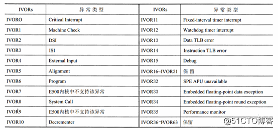
Figure 1. 1 E500 Core Interrupt Vector Table
1.1 External interrupt processing flow
The external interrupt of E500 core consists of three parts, namely Machine Check exception, Critical Interrupt exception and External Input exception. In the E500 core, Machine Check exceptions are edge-triggered , while Critical Interrupt exceptions and External Input exceptions are level-triggered .
In the PIC , the P2020 processor sets some register bits to map the interrupt as level or edge trigger, but these interrupt trigger conditions need to be passed to the E500 core in the form of level. The E500 core both enters an interrupt and returns from an interrupt
To switch the program context. Frequent interrupts will greatly affect the efficiency of the processor. In the E500 core, a complete interrupt processing flow is as follows:
1. The E500 kernel captures the hardware interrupt signal cint , int or mcp .
2. After the E500 core captures the hardware interrupt signal, it needs to make some necessary preparations before entering the external interrupt handler. These preparations bring some delays in the processing of external interrupts, which are unavoidable. First, the E500 core clears all instructions in the instruction completion queue CQ , except for the following three instructions:
1) The read operation instruction to the protected area (Guarded) in CQ0 .
2) Instructions for prohibiting the operation of the Cache memory area.
3) stwcx. instruction.
After these instructions are executed, the E500 core can enter the interrupt mode. After clearing the CQ , the E500 interrupt processing module prefetches instructions from the corresponding interrupt vector into the IQ . The main purpose of the preprocessing of these interrupts is to prepare a "clean" space for the interrupt handler to ensure that the interrupt handler and the interrupted program do not interfere with each other. It can be seen that before the E500 core enters the interrupt handler, the instruction synchronization operation is implicitly performed.
3. The E500 core saves the return address of the interrupt program in SRR0 ; saves the MSR register of the program in SRR1 . For some special exceptions, such as DSI , ISI and TLB Miss , the E500 core will automatically reserve some other registers of the E500 core.
4. The E500 core reserves the CE , ME , and DE bits of the MSR register , and clears all other bits to zero. Therefore , the E500 core can still be reentrant by Critical interrupt, Machine check interrupt and debug interrupt program when performing external interrupt handler , but cannot be reentrant immediately by external interrupt. In Linux PowerPC , the external interrupt handler will select the appropriate time to enable the EE bit of the MSR register to support the heavyweight of external interrupts.
5. The PR , EE , IS and DS bits in the MSR will be cleared, so the E500 kernel runs the interrupt handler in the super user mode, and the access to the program space and the data space must be carried out on the address space 0 .
6. The E500 core will determine the interrupt vector according to the IVPR and IVOR4 registers to execute the interrupt program.
7. After the interrupt handler is executed, use the rfi instruction to return from the interrupt. The rfi instruction will restore the value of the MSR register from the SRR1 register and obtain the program return address from the SRR0 register. The rfi instruction also synchronizes the instruction and data before switching the program text, and returns a "clean" space to the interrupted program, and then the E500 core returns from the interrupt.