Tensilica is a rapidly growing company. The company's main products are microprocessors for professional applications, providing the best solutions for today's high-capacity embedded systems. The company was established in July 1997. The company’s investors include three well-known venture capital companies: Oak Investment Partners, Worldview Technology Partners and Foundation Capital, and five well-known companies in the high-tech electronics industry: Cisco Systems, Inc, Matsushita Electric Industrial Company Ltd, Altera Corporation, NEC Corporation and Conexant Systems. The founder of Tensilica is Chris Rowen, who is also the first CEO. He used to work for Intel, Stanford, MIPS, SGI and Synopsys. He is also the proponent and practitioner of reconfigurable processing ideas. The purpose of Tensilica's creation is to provide a reconfigurable, ASIC-based, dedicated microprocessor solution with corresponding software development tools.
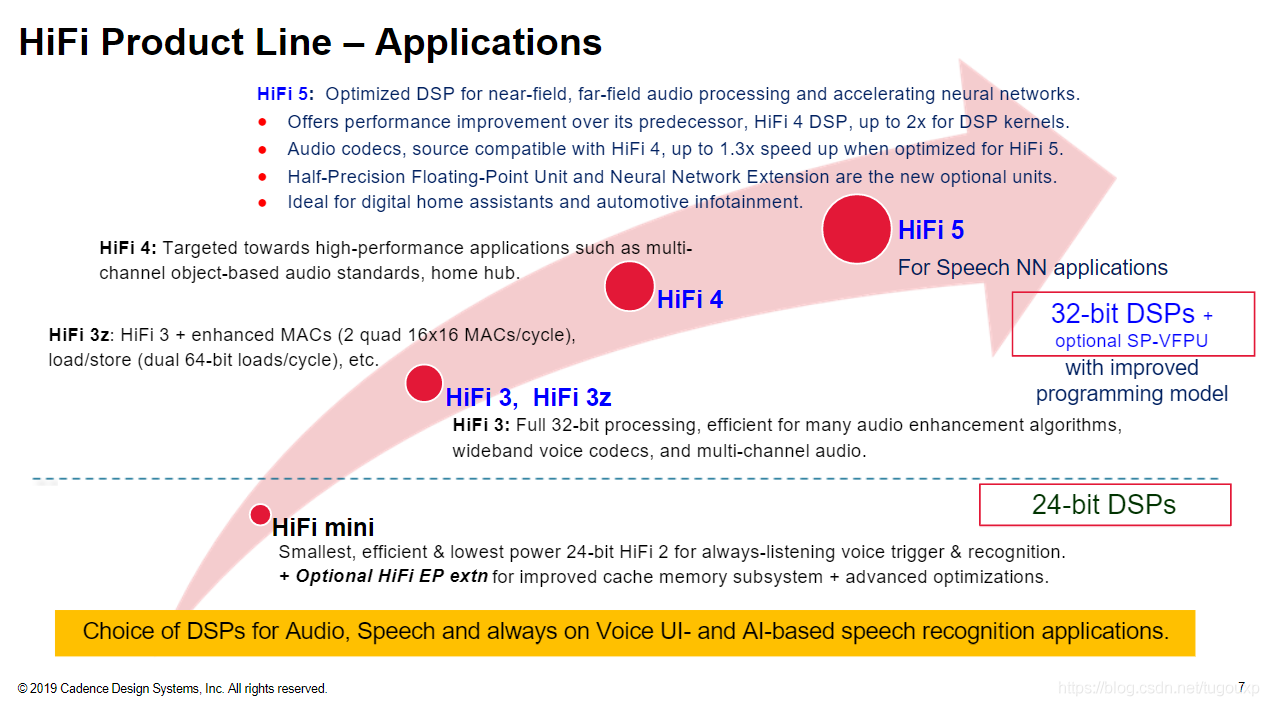
The main applications of its HIFI series products include:


As a configurable processor core, Xtensa processor supports instruction expansion. Users can encapsulate common logic into circuits and add new instructions to call, for example:

f represents a function, which can be either FFT or any algorithm such as CRC.
1. In order to better support the efficient compilation of high-level programming languages, modern processors usually have 16 or even 32 general-purpose registers. So many registers can achieve depth in more complex applications. When nesting calls, in order to ensure the correct execution of the program, registers must be frequently pushed into and out of the stack. Such frequent stack memory access will significantly reduce the performance of the application. In order to effectively solve this problem, tensilica's Xtensa architecture A register management mechanism in Windows rotation mode is designed to separate the logical register and the physical register. When the function is called, the logical register is switched by sliding windows to avoid register coverage. An abstraction is added to the design to reduce stacking and stacking. The stack operation improves performance to a greater extent. The following figure shows the register window implemented on 64 physical registers. Although the ISA only defines 16 AR registers, the actual microarchitecture design is not limited to the number of physical registers. Of course, the cost increases with the number of microarchitecture registers. And increased.

A more specific mapping example:

Regarding the working mechanism of the register window, WindowBase cooperates with the src and dst fields in the instruction to realize the working principle of the final physical register addressing, which can be represented by the following figure. The numbers beside the slash in the connection indicate the data bit width, as shown in the figure below It represents an addressing scheme implemented by the micro-architecture of 64 32-bit physical registers.

The number of physical registers is limited. If call 4/8/12 is nested in multiple layers, the original register window will be overwritten. When overwriting occurs, Xtensa handles this situation through register window exceptions. In the register window mechanism, any reference to a0-a3 will not generate a register window exception. The user can use it in c or assembly code at will, because in any environment, the register of the current logical window either has no overwrite or is already in The call/entry instruction is pushed to the stack. The high register reference of a4-a15 will trigger the coverage detection of the low register, even if the low register is not shown, the trigger sequence is overflow4 first, then overflow8 to overflow12.
Execution pseudo code of entry instruction:


2. The difference between ESP32 and HIFI3/4/5

The ISA of HIFI3/4/5 is the same. The difference may lie in the number of resources and the implementation of the execution unit.

to sum up:
- On the basis of the Xtensa core, the HIFI series integrates DSP Extensions, such as integrating the VLIW computing unit to accelerate various DSP operations, etc. The ESP32 core does not have these extensions.
- The base ISA part of ESP32 and HIFI series should be the same, which is somewhat similar to the design of RISCV ISA RV32I/64I extensions. However, the same Base ISA does not mean that the characteristics of the processor are exactly the same, especially the Xtensa support reconfigurable processor design architecture, it is very easy to extend new instructions, so the HIFI series is implemented as the DSP of the xtensa core. It must be added to support fast DSP operation DSP instructions. ESP32 is not a DSP, it does not have these.
- ESP32 does have some 32bit mac single instructions, such as single-cycle multiply and accumulate instructions. Although it can also be used to do some DSP operations, it is completely different from the HIFI core approach. The HIFI core is implemented based on hardware vector and VLIW. , Is oriented to DSP processing, and the performance is definitely not at the same level.
- In fact, there is a project on github that implements an algorithm library that uses ESP32 for DSP-like operations. esp-dsp project .
- HIFI5 DSP is a configuration option of the LX series processor, which can be added to the LX series processor core to form a DSP core. Of course, it is not a DSP if it is not added. When the extended configuration of DSP is used, the compiler will automatically use HIFI5 DSP for instructions Compile in an accelerated way.
- HIFI5 DSP is built on the baseline of Xtensa RISC Architecture. Its most powerful capabilities come from the DSP instruction set and audio instruction set extension, not the baseline ISA. If you want to see the baseline ISA, you can use esp32 or esp8266 to experience it.
- The HIFI series processors can transmit up to 5 instructions at the same time (no structure, data related), and pack these five instructions into 128-bit ultra-long instructions, and distribute them to five sets of VILW Machine slots execution units for execution. There are structure-related instructions that cannot be packaged together into VLIW. For example, because only slot0 supports store operations, it is impossible to package two or more memory store operations to execute at the same time. Other instructions that rely on slot capabilities are also limited, depending on each slot. Support information.
- It seems that xtensa is very confident in the register scheduling capabilities of its own compiler xcc, so it is not recommended for users to rub DSP assembly on HIFI5.
- Compared with HIFI4 and HIFI5, the performance has been enhanced, including the number of VLIW machine slots (4 for HIFI4, 5 for HIFI5), which makes HIFI have stronger computing resources, such as MACs, and load/store bandwidth. Among other aspects, HIFI5 It has also been enhanced. But from the perspective of software development, HIFI4/5 are all based on Xtensa LX processor, and support XEA2 exception models.
- The ESP32 has the MAC16 which adds some 16-bit multiply/add instructions to the ISA, but it does not have HiFi extensions. I think this may mean there are no VLIW machine slots, but I'm not sure... There's some examples of this here if you're interested; the linked code compiles for & runs on an ESP32.
- Window ABI has a limitation that all the codes should be put in the same GB region. e.g. 0 ---- 0x3FFFFFFF or 0x40000000 --- 0x7FFFFFFF, call4/call8/call12 has the effective range (524284 to 524288 bytes). But they have another long call version: callx4/callx8/callx12 which can be enabled by compiler option -mlongcalls. Complier will automatically use them if required. They can allow a call in the 1GB region.
- The Xtensa ISS (invoked with xt-run) supports two major simulation modes, cycle-accurate and fast functional, which the user specifies via a command-line option. In the default cycle-accurate mode, the ISS directly simulates multiple instructions in the pipeline cycle by cycle, modeling most micro-architectural features of the Xtensa processor while maintaining a very high degree of accuracy. In this mode, the ISS can be used as a reference model for a detailed hardware simulation.
In the fast functional (or TurboXim) mode, the ISS does not model the micro-architectural details but performs an architecturally correct simulation of all Xtensa instructions and exceptions. For long-running programs, the fast functional simulation can be 40 to 80 times faster than the cycle-accurate simulation, which makes it ideal for high-level verification of application software.
Our ISS models iDMA and memory, but does not currently support QEMU – which would allow expansion of other system IP. However, we have another tool (XTSC) that supports both transaction-level modeling and pin-level modeling of the Xtensa cores in a SystemC or SystemC/Verilog environment. And we have customers currently co-simulating XTSC alongside other IP on QEMU.
The Xtensa LX processor has a function called FLIX (Variable Length Instruction Extension), which allows the processor to mix the existing 16-bit and 24-bit Xtensa instructions to generate customized wide instructions, VLIW diagram, slot is the execution unit, each capability Different, you need to pay attention to the instruction cannot be structurally related.

3. According to the information about xtensa from Google, some information about the application scenarios and usage of VLIW is extracted, including a total of ten instruction packaging formats. Each format differs in the resources used, application scenarios, and instruction length.

4: According to experience, under normal circumstances, there are two ways to define the exception entry of the processor ISA and expose it to the software. The
first is the entry address of the ISA fixed exception. For example, the previous arm9 only has two 0x00000000/0xffff0000. A choice, the start vector of mips is 0xbfc00000 and so on.
The second type: ISA provides an exception base address register, and the software can write the exception entry address, so that the exception entry can be placed anywhere in the address space, such as the riscv/cortex-a series.
But in the spec of xtensa, I did not see the definition of the entry address, nor did I find in the code to configure the exception entry to a certain register (after software decompilation, I looked for the symbol table, but I did not find the exception symbol set to a certain register. (Logic)
So the confusion is that I know that it will call an exception handling function when an exception occurs, but I don't know where the execution flow comes in!
So, if the above two options are no, what is the third exception handling method? Could it be that the entry address is determined during HW digital design, and then the configuration file (here is the link script xmm) is generated, and the software puts the abnormal code in the correct place according to this configuration file, so that I can understand it.
After confirmation, xtensa handles this way, that is to say, the address of the exception vector table can be remapped, which is also an aspect that it claims to be a reconfigurable processor. It can be known by investigating the compilation and linking method of esp32/exp8266SDK, soft core The xmm file generated by the reconstruction generates the link script. The software lays out the code and data according to the generated link script. Therefore, the address and the abnormal entry logic in the HW are bound. After the chip TO, if I modify the xmm file again, it will cause an abnormality. If the entry code is inconsistent with the actual hardware, if the CPU enters the wrong entry processing program, problems will occur.
However, software often says that to solve a problem can be solved by adding a layer. This statement also applies to hardware. After all, they are all languages. When digital design, some registers can be configured on the periphery. These registers are not part of xtensa ISA. Through the logic set by these registers, the exception entry can be flexibly set to achieve an address effect similar to riscv mtvec/stvec or cortex-a CP15 vbar.
The reconfigurable processor is more flexible. It can generate HDL code according to different configurations. To change the function of the processor, you only need to reconfigure the generated code. This is a bit similar to the configuration header file in software development, isn't it?
5: ESP32 xtensa architecture freeRTOS startup process, pay attention to the operation of calling the wsr.vecbase instruction to set the windowoverflow exception entry.

Regarding the setting of WindowOverFlow, the base address is set by "cpu_hal_set_vecbase" in ESP32.


6: ESP32 exception handling architecture:

7: Timing of Xtensa ISA Windows check, note that the entry command will also trigger a windowoverflow exception.

8: Xtensa ABI:

Window ABI and Call0 ABI cannot be mixed, of course, except for the safe hand-rubbing assembly that contains call0.

9: In-depth analysis of Xtensa's register window mechanism
Download the code that supports xtensa LX series processors from the freeRTOS development warehouse maintained by cadence on github. This warehouse is provided by cadence and is open source.
git clone https://github.com/foss-xtensa/amazon-freertos.gitWindow ABI is a major feature of the Xtensa architecture, and it is also the most difficult to understand. The call of call4/call8/call12 will affect the registers used by the callee function. Between the child function and the parent function, the same register name corresponds to Different physical registers are difficult to imagine in architectures such as ARM, X86, MIPS or RISCV, which also poses a big obstacle to the understanding of Xtensa architecture.
After in-depth analysis of Xtensa's documentation, it is found that although the learning curve of its register window concept is very steep, it is mainly due to insufficient understanding of the document and missing many details. In fact, the core logic of register window conversion and when the window occurs The WindowOverflowException handling that the processor needs to do during coverage is introduced in the ISA architecture document, but the English reading is rather jerky. After reading the relevant chapters a few times, I gradually feel a little bit.
After summarizing, in fact, its register window has a strong assumption on the system software. This assumption is mandatory, that is, the top level of the call stack of all threads. Either use call4 to initiate a call to the first function, or compile by hand. Manually fabricate a call that conforms to call8 exception handler or call12 exception handler to meet the top-level logic triggered by WindowException. This logic is that WindowOverflow8/12 needs an initial base save area to obtain the stack pointer, as shown in the figure below:


It can be seen that _WindowOverflow8/_WindowOverflow12 needs to obtain an SP from the stack at the beginning of the exception. The source of this SP is either initialized through _WindowOverflow4 generated by call4, or manually fabricated a stack layout to ensure that the window register mechanism can operate effectively.
After analysis, a three-level function call stack layout is as follows:

For the same reason, when the FreeRTOS thread creates the initial stack filling, since there is no call chain at the upper layer of the thread entry function, in order to ensure that the register window can work normally, it is necessary to forge a call4 site. The method is as shown in the screenshot below:
The code is in the implementation of freertos/kernel/FreeRTOS/portable/XCC/Xtensa/port.c pxPortInitialiseStack function.

By opening the window register (WOE), setting PS_UM (user exception) and the most important CALLINC (1), which corresponds to the callinc of call4, the purpose of setting EXCM to 1 is to ensure that rfe returns abnormally.
When the thread entry function executes the entry instruction, the callinc set here will be used.
10: Regarding whether the initialization stack needs to be initialized and how to initialize the logic:
If you need to initialize, you need to follow the steps below:

Under what circumstances do not need to be initialized:

When must be initialized:

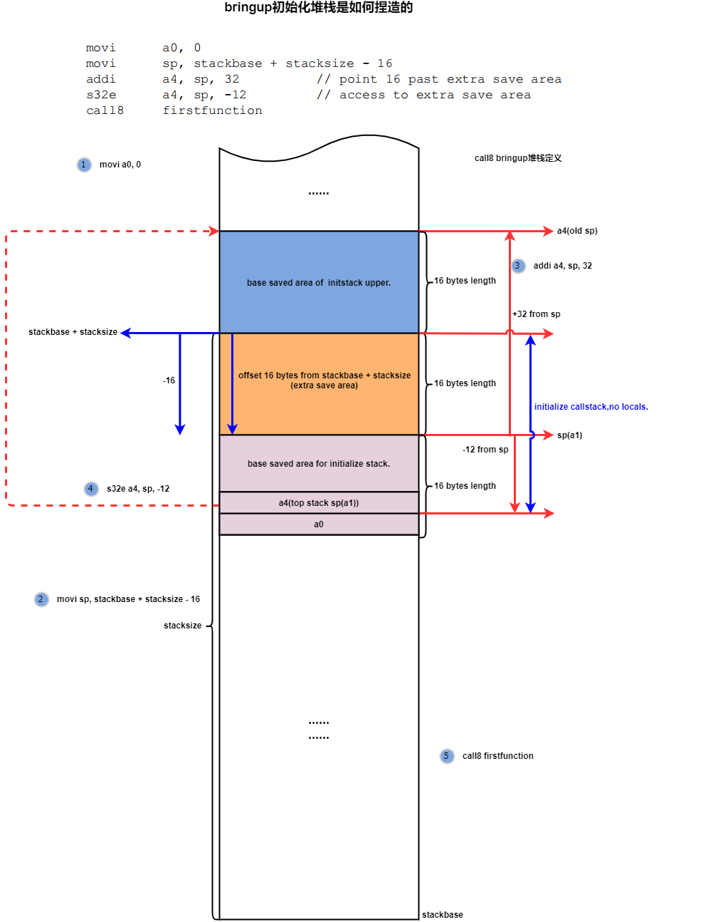
12:call8/call12 Initialize the logic fabricated by stack manually, pay attention to the following points:
1. The blue part is the current stack hand-rubbed by the bringup initialization process, which represents the stack used by the bringup assembly, which is generally the process with the _start flag.
2. This stack has no local object, only the extra save area in the brown part and the base saved area in the purple part below. This is well understood. The stack fabricated during the assembly phase does not need storage in the stack itself.
3. The execution process is that if the call chain initiated by firstfunction covers this layer of registers in a function call, the window will rotate to the register window view represented by call8, and perform WindowOverflow8 exception handling. In the process, first Get the sp(a1) of the last stack frame stored in the address of sp-12. In fact, this stack frame is fabricated. Where there is the previous stack frame, the purpose of taking the upper level sp here is to only pass the sp of this layer. In addition, 16 bytes of cheap skip and base saved area (blue part) can be added to address the yellow part of the extra save area.).
4. In WindowOverflow8, continue to pass a9, which is the stack address of the firstfunction, and save the values of a0-a3 in the bringup stack to the base save area of the firstfunction.
5. The purpose of fabricating a stack for call8/12 is to simulate the presence of a call4 call in the upper layer, which has already occurred a windowoverflow4 exception, and save its own sp in the base save area of call8, so that for the call8 layer, it can be Address to the extra save area of this layer through the value of the saved sp.
The a0-a3 of call8 itself are saved in the base save area of callee.
The initialization stack of call12 is similar to that of call8, and the details are different. Call12 takes into account the space for parameter transfer and local variables. For parameter transfer, it takes into account that 16 bytes of space are reserved for a8-a11 in the extra save area, and then again Loc bytes that are integer multiples of 16 bytes are reserved as space for stack local variables.

After the fabrication of this stack, the first c function call at the source of the thread can be implemented without call4.
I have to say that the stack layout of Xtensa is too ruinous. After reading Xtensa, I look back at ARM and RV. I feel that ARM and RV are much more cute.
13: In order to consolidate the understanding of Window Register ABI, continue to analyze setjmp, the function most closely related to the software ABI.
Xtensa's struct jmp_buf is defined as follows:


14: The impact of special instructions on special registers

15: The logic of WindowCheck

16: It seems that the xt-xcc compiler can only generate call8 instructions when compiling c code, and call4/call12 can only be realized by the user's hand rubbing assembly. See the frequency of use of call4/8/12 in the following executable file.
call0 is an independent ABI and can only be rubbed by hand, unless the system selects CALL0 ABI instead of Window ABI.

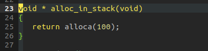
The alloca stack allocation memory instruction will generate a "movsp" instruction, which does not seem to be too many:

For example, the movsp instruction in the figure below is generated because alloca is called in alloc_in_stack.


to sum up:
1. Call8 requires 16 bytes for extra save area and 16 bytes for base save area, so the entry at the entrance is at least 32.
2. Call12 requires 32 bytes for extra save area and 16 bytes for base save area, so the entry at the entrance is at least 48.
3. Since C code compilation only uses the call8 instruction by default, for non-leaf functions, the entry must not be entry 16. For leaf functions, it seems that the c compiler also starts with entry 32. In fact, in order to save space, it should be possible Hand-rub assembly starts with entry 16, and then internally calls with call4 or does not make function calls.
4. According to the working principle of the register window, since the register window is rotated to the new register view when the child function is called, there is no register conflict between the parent and child functions, that is to say, the useful registers of the parent function will not be stepped on by the child function. Therefore, the parent function does not need to be saved. Similarly, the child function does not need to be afraid of stepping on and destroying the execution site of the parent function. The child function will only destroy the call site further away in the call chain and trigger a WOF Exception.
The hardware execution logic of the movsp instruction will trigger an alloca exception in the middle to move the base save area [sp-16, sp] of the current stack to the new range of [as-16, as], which is a way of lazy restore.

Exception handling flow:

17: The native xt-xcc of xtensa does not seem to support "__builtin_apply_args" "__builtin_apply" "__builtin_return" several GNU GCC built-in extensions, I don't know how well the xtensa gcc support of ESP32 is.

18: The ill/ill.n instruction is similar to the unimp instruction of riscv, which is used to unconditionally trigger an illegal instruction exception, which is used for debugging in the software


19: About the interrupt logic of xtensa:
1. The higher the interrupt LEVEL number, the higher the priority of the interrupt, so the priority of Level-1, Level-2, Level-3,... gradually increases.
2. EXCMLEVEL sets a relatively large number by default, which means that most interrupts can be masked. When an exception occurs, PS.EXCM is 1. The formula shown in the figure below, the exception level CINTLEVEL of the processor is determined by the product of PS.EXCM. Therefore, most interrupts will be shielded when the exception occurs. This method of shielding interrupts in exceptions,
MPS, ARM, and RISCV all have similar implementations, which is not surprising.


3. According to the different configuration of PS.UM, exceptions can go to KernelExceptionVector or UserExceptionVector, UserException can switch the stack before processing, and KernelException directly uses the kernel stack.

4. Regarding the interrupt priority, NMI is the highest, and DEBUG is the second. As the level is smaller, the priority is lower. DEBUG level is an interrupt whose priority is second only to NMI.

5. The interrupt register function is similar to the interrupt pending register on the general-purpose processor, marking the interrupt request that is currently active and pending.

6. Interrupt handling process:

7. When using the Xplorer ISS simulator to run the FreeRTOS test case project, it has been compiled, but the link is always not at the last step. The reason is that the exception handling in the FreeRTOS native code xtensa_vector.S uses the call0 instruction, but due to the xtensa instruction The coded offset field is only 18bit, the unit is WORD, and the conversion is only supported
The offset is 1M byte, and the linker links the function behind call0 to an address that is more than 1M away when linking, so linking is not possible. Similar problems also exist in MIPS.
In order to solve this problem, according to the xt-xcc manual, you need to add a compile option when compiling:
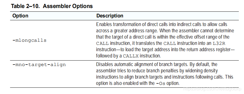
Originally I wanted to add the -mlongcalls compilation option through the build configuration page of xplorer. I tried too many and I was unsuccessful. It may be because I am not familiar with this set of tools. Later I simply modified the following assembly code by myself, as shown in the figure below. The left side is the modification. Later, I changed the call0 instruction into a load instruction and a callx instruction. It is found that different architectures add the suffix -x after the jump to indicate the register jump. This is the same. For example, arm bx, mips jalx, riscv also have jumps with the suffix x Transfer instructions.

Depending on the bit width of the immediate data, the compiler judges whether to compile the movi instruction into the l32r instruction
