Duality in logical algebra: If all "·" in the logical function expression F becomes "+", "+" becomes "·", "0" becomes "1", and "1" becomes "0", and keep the order of operations in the original function unchanged, the new logical expression obtained is called the duality of the function F, and is denoted as F'.
F=AB+B(C+0) F'=(A+B)(B+C·1)
Positive logic: Use high power to represent logic 1, and low power to represent logic zhi0.
Negative logic: Use low to represent dao logic, and use high to represent logic 0.
There is a simple logic between positive and negative logic. Dual relationship, for example, a positive logic AND gate is equivalent to a negative logic OR gate.
In the logic design of digital systems, if NPN transistors and NMOS transistors are used, the power supply voltage is positive, and positive logic is generally used. If the PNP tube and PMOS tube are used, and the power supply voltage is negative, it is more convenient to use negative logic.
BCD code, 8421 code, remaining three codes, Gray code
A four-digit binary code is used to represent a decimal number, which is called two-decimal code, or BCD (Binary Coded Decimal) code for short. According to whether each bit of the code has the right value, the BCD code can be divided into two types: the right code and the unauthorized code. The 8421BCD code is the most used. The unauthorized code is the remaining three codes and the Gray code. We usually The BCD code refers to 8421BCD code. The relationship between these codes and decimal numbers is as follows:
Decimal number 8421BCD code Remaining 3 codes Gray code
0 0000 0011 0000
1 0001 0100 0001
2 0010 0101 0011
3 0011 0110 0010
4 0100 0111 0110
5 0101 1000 1110
6 0110 1001 1010
7 0111 1010 1000
8 1000 1011 1100
9 1001 1100 0100
The "8421" in the 8421BCD code means that the corresponding weights of the binary digits from high to low are 8, 4, 2, 1, respectively. Multiply each binary digit with the weight, and add the product to get the corresponding decimal number. . For example, 8421BCD code "0111", 0×8+1×4+1×2+1×1=7D, where D stands for Decimal number.
It is worth noting that there are only ten 8421BCD codes from 0000 to 1001, and 1010, 1011... etc. are not 8421BCD codes! !
The remaining three codes are obtained by adding 0011 (corresponding to the decimal number 3) to the code of each number on the basis of the 8421BCD code. The encoding rule of Gray code is that only one binary bit is different between two adjacent codes. Regardless of the 8421BCD code, the remaining three codes, or the Gray code, 4 binary digits always correspond to a decimal number. For example, the 8421BCD code corresponding to the decimal number 18 is 0001 1000.
The compressed BCD code uses 4 binary digits to represent the decimal number. The above mentioned is the compressed BCD code. The uncompressed BCD code uses one byte (eight binary digits) to represent a decimal number, the upper 4 digits are always 0000, and the lower 4 digits 0000 to 1001 represent the corresponding decimal number. For example, the decimal number 87D, expressed as a binary number using uncompressed 8421BCD code, is 00001000 00000111B. This uncompressed BCD code is mainly used in non-numerical computing applications.
TG is the abbreviation bai of transmission gate, that is, transmission gate du. The so-called transmission gate (TG) is an analog switch that transmits analog signals.
The CMOS transmission gate consists of a P-channel and a N-channel enhancement MOSFET, namely TP and TN in parallel. TP and TN are symmetrical devices, and their drain and source are interchangeable. The symmetric circuit structure formed by TP and TN is to ensure that the conduction (transmission) performance is kept as unchanged as possible under the condition of the transmission signal change.
When it is turned on, the amplitude and polarity of the transmission signal will affect the conduction of the two MOS tubes: the deeper the conduction of one tube, the less the conduction of the other tube. In other words, when the on-resistance of one tube decreases, the on-resistance of the other tube increases. Since the two pipe systems run in parallel, it can be approximately considered that the on-resistance of the switch is approximately a constant.
In addition to being a switch for transmitting analog signals, CMOS transmission gates can also be used as the basic unit circuits of various logic circuits.
CMOS transmission gate (Transmission Gate) is a controllable switch circuit that can transmit both digital signals and analog signals. The CMOS transmission gate is composed of a PMOS and an NMOS tube in parallel, which has a very low on-resistance (a few hundred ohms) and a very high off-resistance (greater than 10^9 ohms)
Field effect transistor (Field Effect Transistor abbreviation (FET)) is referred to as field effect transistor. There are two main types: junction FET (JFET) and metal-oxide semiconductor FET (MOS-FET). Participation in conduction by majority carriers, also known as unipolar transistors. It is a voltage controlled semiconductor device.
1. What is FET
FET is the abbreviation of Field Effect Transistor and is called Field Effect Transistor. It is a type of transistor. Generally speaking, the transistor refers to a bipolar transistor.
The working mode of the field effect transistor is that the majority of carriers in the channel drift from the source to the drain under the action of an electric field, forming a drain current. Only involves
It is a kind of drift effect of carriers, so it is also called unipolar transistor.
The FET has three electrodes, namely the gate (Gate), the source (Source) and the drain (Drain).
Tips:
Bipolar transistor, full name bipolar junction transistor (bipolar junction transistor, BJT), commonly known as triode, the charge flow in the transistor is mainly
Due to the diffusion and drift movement of carriers at the PN junction. The work of a bipolar transistor involves the flow of both electrons and holes at the same time, so it
It is called bipolar, so it is also called bipolar carrier transistor.
Second, the working principle of FET
The triode controls the current at the output end (collector) by the current flowing at the input end (base), which is a flow control element. The FET is added to the input
The voltage (gate) controls the current at the output (drain), which is a voltage-controlled current component.
The figure below is a schematic diagram of the internal workings of the FET. The FET continuously monitors the voltage applied between the gate and the source, and controls the current source between the drain and the source to make it flow
The current is proportional to its voltage.

Three, the classification of FET
As shown in the figure below, FETs can be divided into junction FETs (JFET: Junction FET) and insulated gate FETs (MOSFET: Metal Oxide Semiconductor FET) according to their structure.
According to electrical characteristics, MOSFETs can be divided into two types: depletion and enhancement. They can be further divided into N-channel type and P-channel type.

Fourth, the structure of FET
The figure below is a schematic diagram of the simple structure of the FET.
There is a PN junction between the gate of the JFET and the channel (the channel between D and S is called the channel), so it is considered that there is a diode (due to the PN junction, it is called a junction FET).
The diode between the gate and the channel of the JFET works in an off state. Therefore, the current flowing between the gate and the channel is very small, which is only equivalent to the reverse leakage current of the diode, so the input impedance of the JFET is very high (about 10^8 ~ 10^12 Ω).
The gate of the MOSFET is made of metal, and there is an insulating film between it and the semiconductor channel to form a three-layer structure. The so-called MOS is because the actual structure is composed of metal (M), insulating film (such as oxide film, O) and semiconductor (S).
The characteristic of MOSFET is that there is an insulating film between the gate and the channel, and the gate and the channel are insulated, so the current flowing through the gate is much smaller than that of the JFET. Therefore, the input impedance is also much higher than JFET (about 10^12 ~ 10^14 Ω).

5. The description of the field effect tube symbol is as follows: (If it is a P channel, the arrow is outward)

The arrow in the transistor circuit symbol indicates the direction of current flow, while the arrow of the FET does not represent the direction of current, only the polarity of the PN junction.
Tips:
The drain and source of the JFET can be interchanged for use. Because there is no PN junction between the source and drain of the JFET, they are made of semiconductors of the same conductivity type.
High-frequency JFET devices have physical changes in the shape of the source and drain. When two FETs are connected in series, the drain and source are different, so the drain and source cannot be exchanged.
The structure of the drain and source of the MOSFET is also different, so the drain and source cannot be exchanged.
Tips:
What are depletion FETs and enhancement FETs?
The depletion type and the enhancement type actually refer to the depletion characteristic and the enhancement characteristic in the transmission characteristic of the FET.
Depletion characteristics: For N-channel JFETs, when VGS is in the negative voltage range, ID flow is called depletion characteristics.
Enhanced features: For N-channel MOSFETs, when VGS is not in the positive voltage range, no ID will flow (the polarity of VGS is opposite for P-channel).
JFETs are all depletion type; MOSFETs are both depletion and enhancement types.
FET is a collective name, that is, field effect transistor, which is juxtaposed with balanced bipolar transistor (transistor).
The full name of MOS tube is MOSFET, that is, metal insulated gate field effect tube, which is a kind of field effect tube.
Is SRAM made of flip-flops?
Flip-flops can memorize H or L, 1-bit information, and after arranging a large number of flip-flops and making them selectable, SRAM can be formed. Since the input and output speed of SRAM is much higher than the access speed of DRAM and flash memory, it is often used as a cache and register of the CPU. Although we say this, in fact, the built-in memory or registers in the CPU do not use logic gates such as RS flip-flops. Since the use of logic gates will increase the circuit scale, generally 4 to 6 FETs are used, and then optimized to form 1 bit of the memory (Figure A). 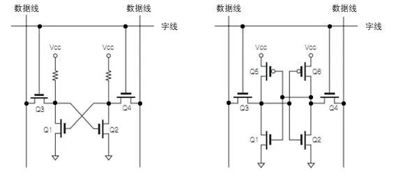 Figure A: Basic circuit of SRAM
The binary counter composed of JK flip-flops can be divided by 2 to the Nth power, N takes 1 2 3...
The frequency of the output terminal is 1/4 times the input clock frequency is divided by 4.


What is a state machine?
It is the state transition diagram. Give the simplest example. People have three states: being healthy, catching a cold, and recovering. The trigger conditions are rain (t1), medicine (t2), injection (t3), rest (t4). So the state machine is health->(t4)->health; health->(t1)->cold; cold->(t3)->health; cold->(t2)->recovering; recovering->( t4)->Health, etc. That's how the state jumps to itself or a different state graph under different conditions.
The state machine can be summarized into 4 elements, namely, current state, condition, action, and second state. This kind of induction is mainly based on the consideration of the internal causality of the state machine. The "present state" and "condition" are the cause, and the "action" and "second state" are the result. The details are as follows:
① Current state: refers to the current state.
②Conditions: also known as "events", when a condition is met, an action will be triggered, or a state transition will be performed.
③Action: the action executed after the condition is met. After the action is executed, it can be migrated to a new state, or it can remain in the original state. The action is not necessary. When the condition is met, you can also move directly to the new state without performing any action.
④The second state: the new state to be moved to after the conditions are met. The "second state" is relative to the "present state". Once the "second state" is activated, it transforms into a new "present state".
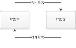
Take the light bulb diagram in physics class as an example, it is the most basic small state machine

Here are two states: ①Turn on the switch, the light bulb is on, ②Turn off the switch, and the light bulb is off
You can draw the following state machine diagram
What should I do if the progress is stuck? There is a relatively vivid case here is Taobao’s automatic confirmation of receipt. After the seller sends the goods, the status becomes pending receipt. If the buyer delays in confirming the receipt, the process will stop here, and the seller will also be delayed in receiving the goods. The payment is not available. Therefore, here, Taobao has made a condition to determine whether the time reaches 15 days, and if it reaches 15 days, it will confirm the receipt of the goods, so that the status can be transferred. Take a small light bulb as an example. Suppose that in order to save money, the light bulb will automatically turn off after being turned on for more than 8 hours, unless the switch is turned on again. The state machine diagram at this time is drawn as follows

but,
Judgment is not necessary for the state machine, such as the two states of a normal small light bulb, it does not need to be judged
The start and end states may be the same or different, that is, the same state may be the start state or the end state
Take Meituan Takeaway as an example, and make a simple state machine diagram

to sum up
The state machine diagram is somewhat similar to the business flowchart, but there are differences:
1. Two different ways of thinking
2. The starting point of the two thinking is different, so the purpose expressed by the two is also different
3. Each node of the two is different, the flowchart is the action, and the state machine is the state
The state machine can sort out the business status, which is clear at a glance, and then can be continuously increased according to business scenarios. At the same time, when using the state machine and related personnel to express, it can also be clearer and improve communication efficiency.
State machines are generally divided into three types:
1. Moore-type state machine: the next state is only determined by the current state, that is, the next state = f (current status, input), output = f (current status);
2. Mealy-type state machine: The next state is not only related to the current state, but also related to the current input value, that is, the next state = f (current status, input), output = f (current status, input);
3. Hybrid state machine.
The differences between the Moore and Mealy state machines are:
The output signal of the Moore-type state machine is directly decoded by the state register,
while the Mealy-type state machine combines the current input signal with the current state that is about to become the next state and encodes it into an output signal.
The output of the Mooer state machine is only related to the current state, that is, the current state determines the output, and has nothing to do with the input at this time. The input only determines the state change of the state machine and does not affect the final output of the circuit. (Note: The output mentioned here is not the output of the state machine state of the state machine, but the meaning of the current state. For example, when the state machine of the 110 sequence is detected, when the state machine jumps to STA_GOT110, the circuit will have a The output signal, if it is find, find will be high at this time, and find will be low in other (in state). Find is the output of our final circuit, and the value of find is set to the current of our turntable machine It is related to the state, and has nothing to do with the output). In the words of a book, each state of the Moore state machine specifies that its output is independent of the input of the circuit.
The output of the Mealy state machine is not only related to the current state, but also related to the current output (similarly, don't mistake the output of the state machine to be the state of the state machine), that is, the current input and the current state jointly determine the current input .