Article Directory
CPT software use
Cisco Packet Tracer
Download the software package on the Cisco official website and install it.
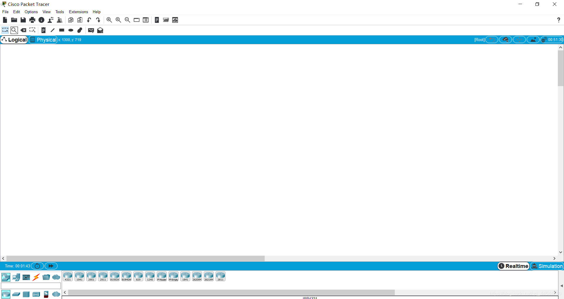
Then open the CPT page as follows:
Refer to https://www.bilibili.com/video/av33482059/ for specific learning
Two PCs are directly connected to build LAN
Build a topology map
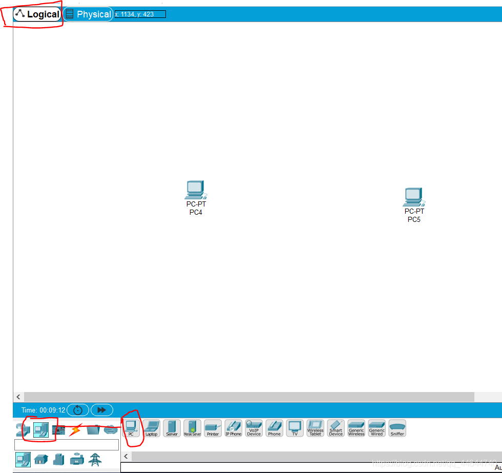
1. Add two hosts in the logical layer, just select and drag them directly:
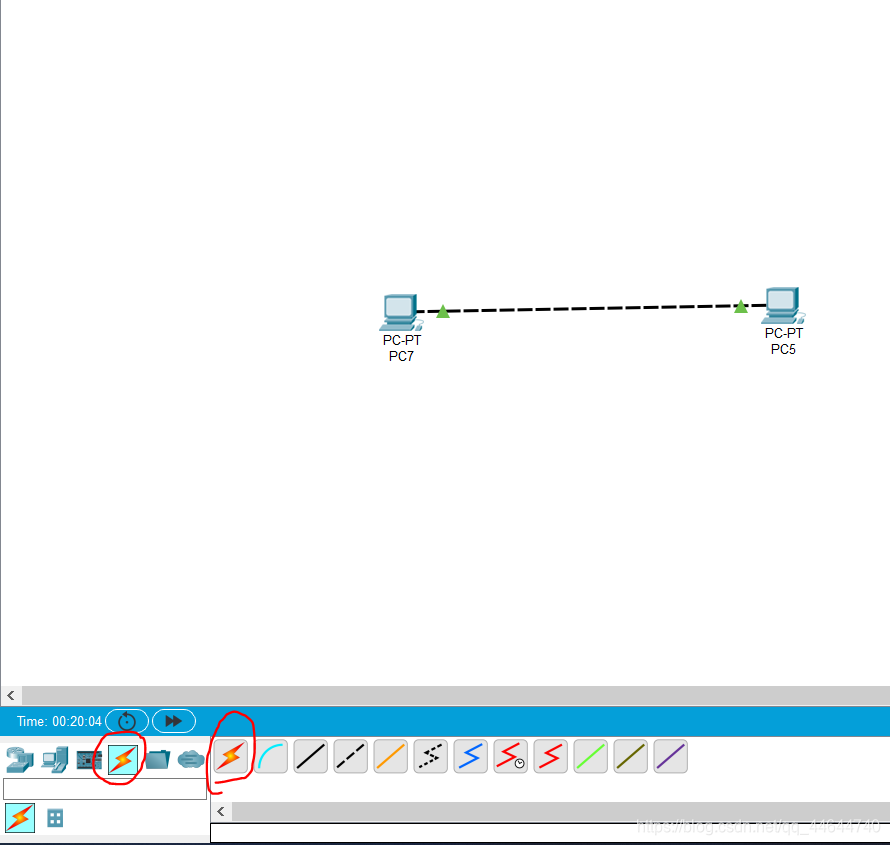
2. After that, there are no interconnected devices between the hosts, and they need to be connected directly, requiring a crossover cable. At this point, we click on the connection, then press "ctrl" and then click the connection symbol, and then click on the protected host to start automatic connection, as follows:
IP configuration
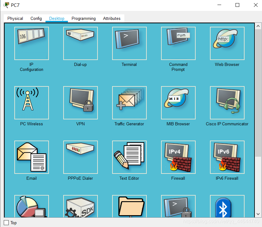
3. Next, configure the IP address, click the host and select the desktop option under the pop-up page, as follows:
4. Click the first icon again, IP address configuration, after entering, just fill in the IP address (10.10.0.1), After filling in, press Enter, the subnet mask will automatically appear as follows: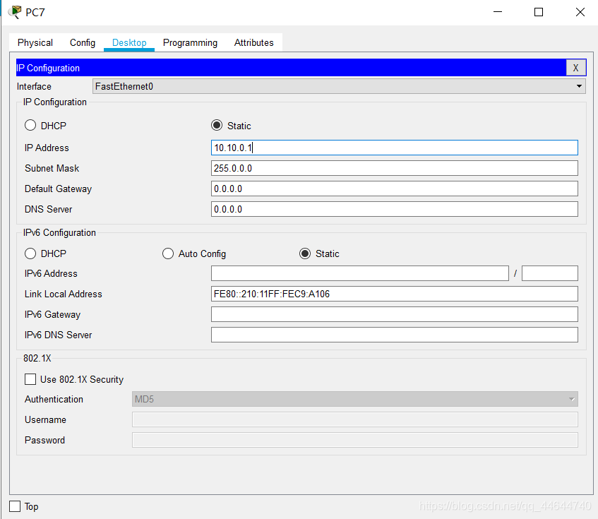
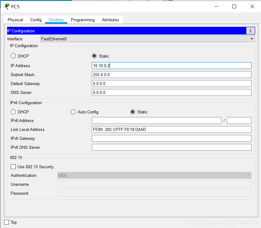
5. Configure another host's IP address (10.10.0.2) in the same way, as follows:
PDU transmission
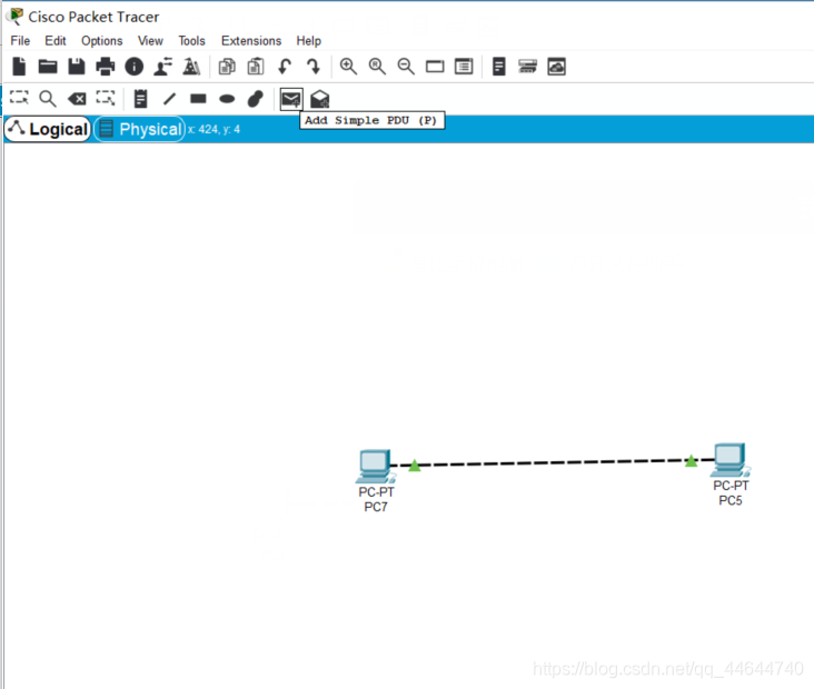
6. After the configuration is complete, a PDU is transmitted between the two hosts to test whether the hosts can communicate normally. Select Add simple PDU in the upper menu bar, as follows:
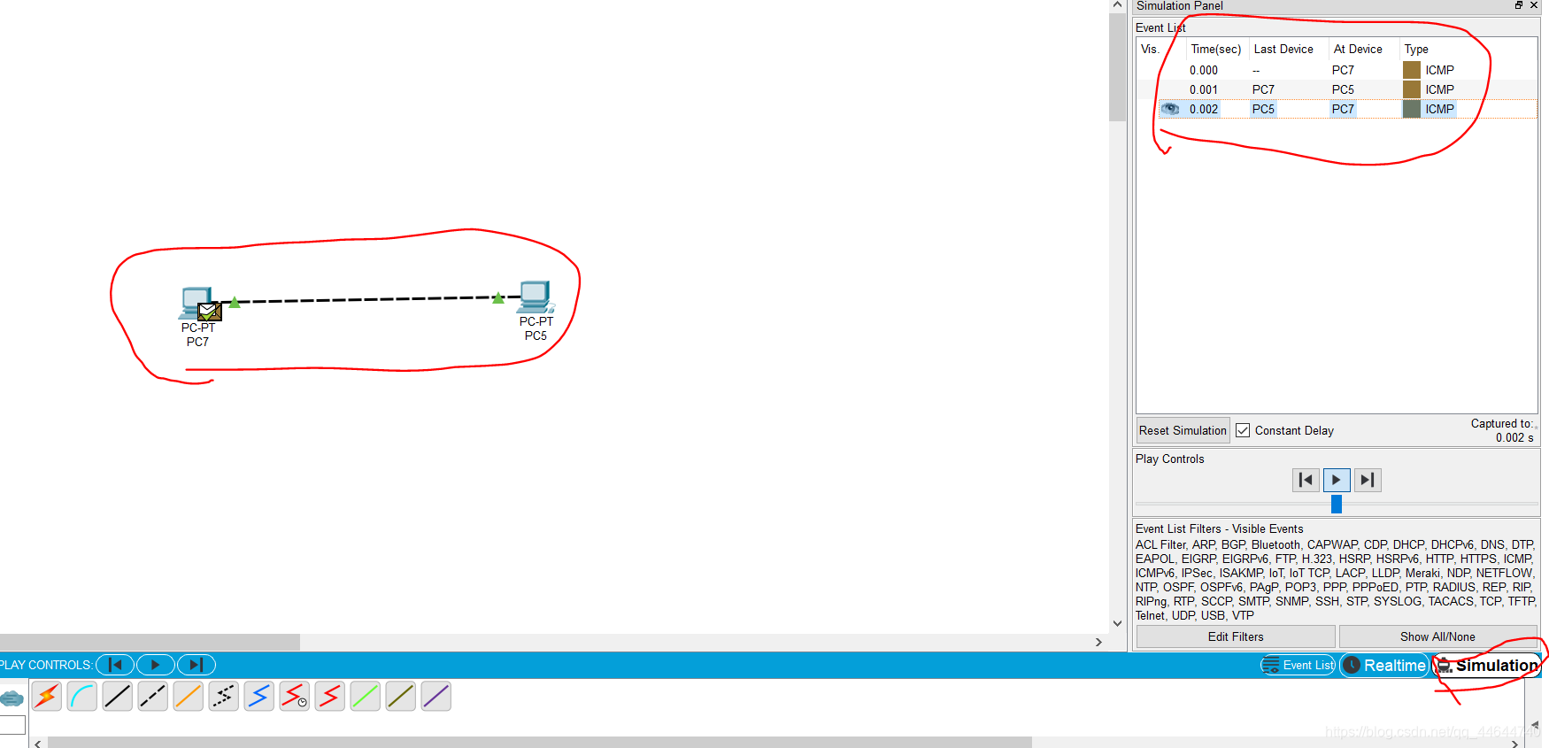
7. After clicking this time, click one host again as the sender, and then click another host as the receiver. If the two hosts complete in an instant without an error, it indicates that the communication between the hosts can be carried out.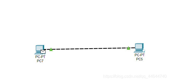
You can see that PC7 has a letter icon. Then click on the host of the receiving end, PC5, and you will find that the icon disappears, indicating that the communication is complete. This is because we are in real-time mode at this time and cannot see the specific transmission process.
8. At this time, you can view the dynamic transmission process, first click the simulation in the lower right corner, then select a transmission, click the starting play icon, you can observe the following transmission phenomenon:

Switch to build LAN
Build a topology map
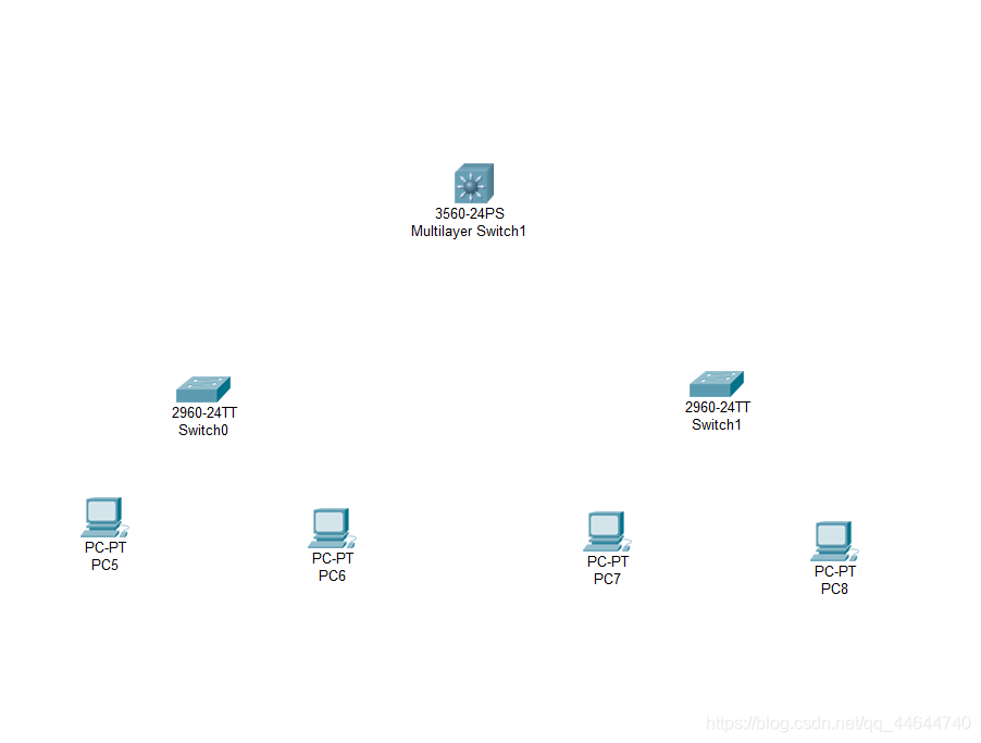
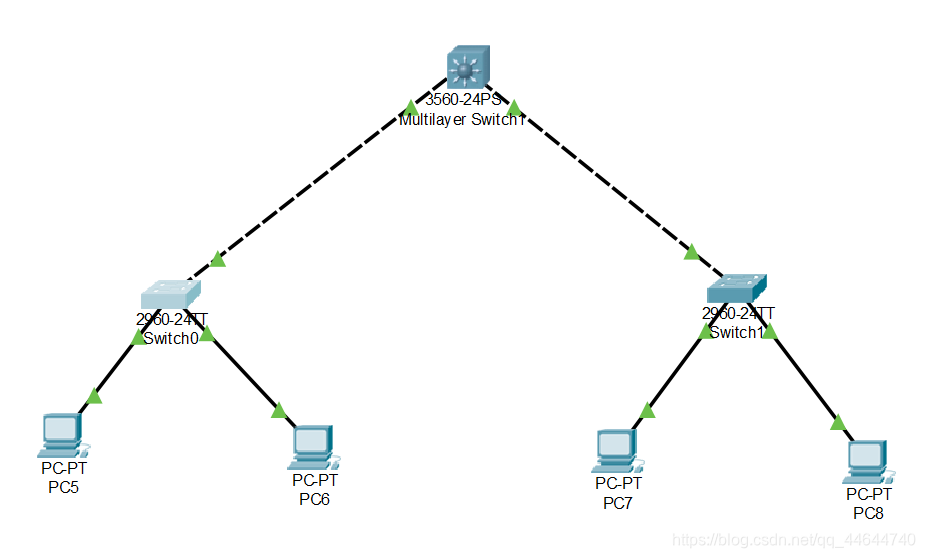
1. Place three hosts according to the method between, and then select the switch. For the selection of the switch type, there is a mark in the lower menu bar, as follows:
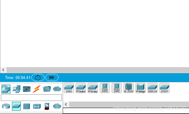
2. Select the switch category and place the switch as follows:
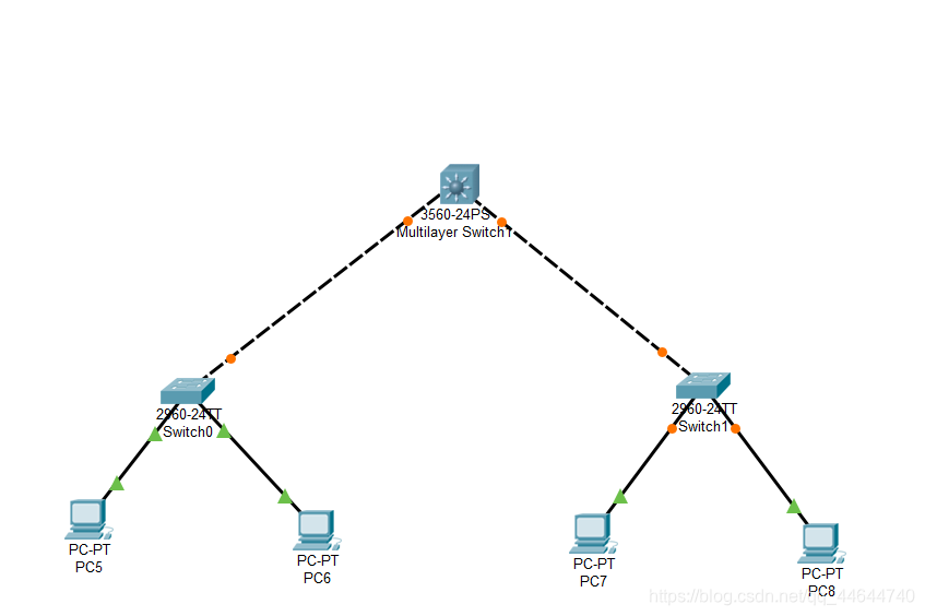
3. Start the connection, the method is the same as the previous article, as follows:
Host network configuration
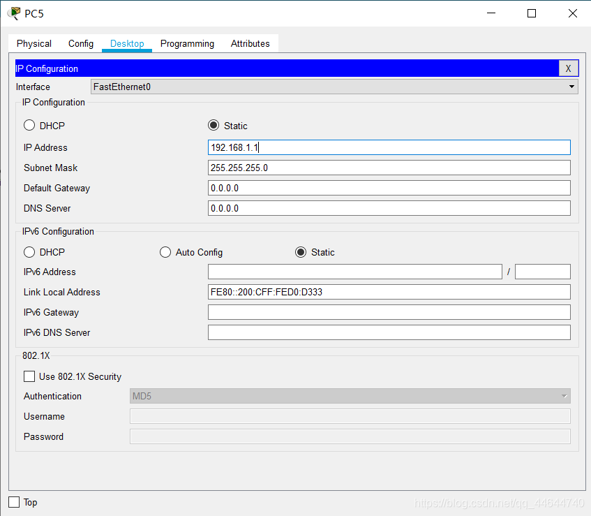
4. PC5 network configuration (IP: 192.168.1.1) is as follows:
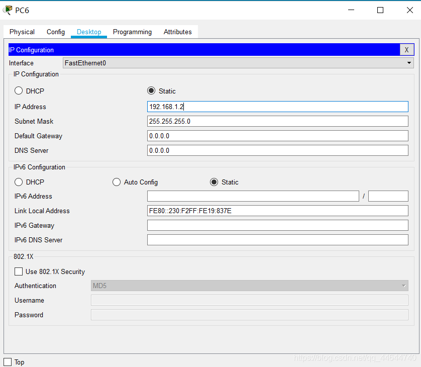
5. PC6 network configuration (IP: 192.168.1.2) is as follows:
6. PC7 network configuration (IP: 192.168.2.1) is as follows: 
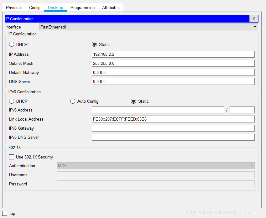
7. PC8 network configuration (IP :192.168.2.2) as follows:

PDU transmission one
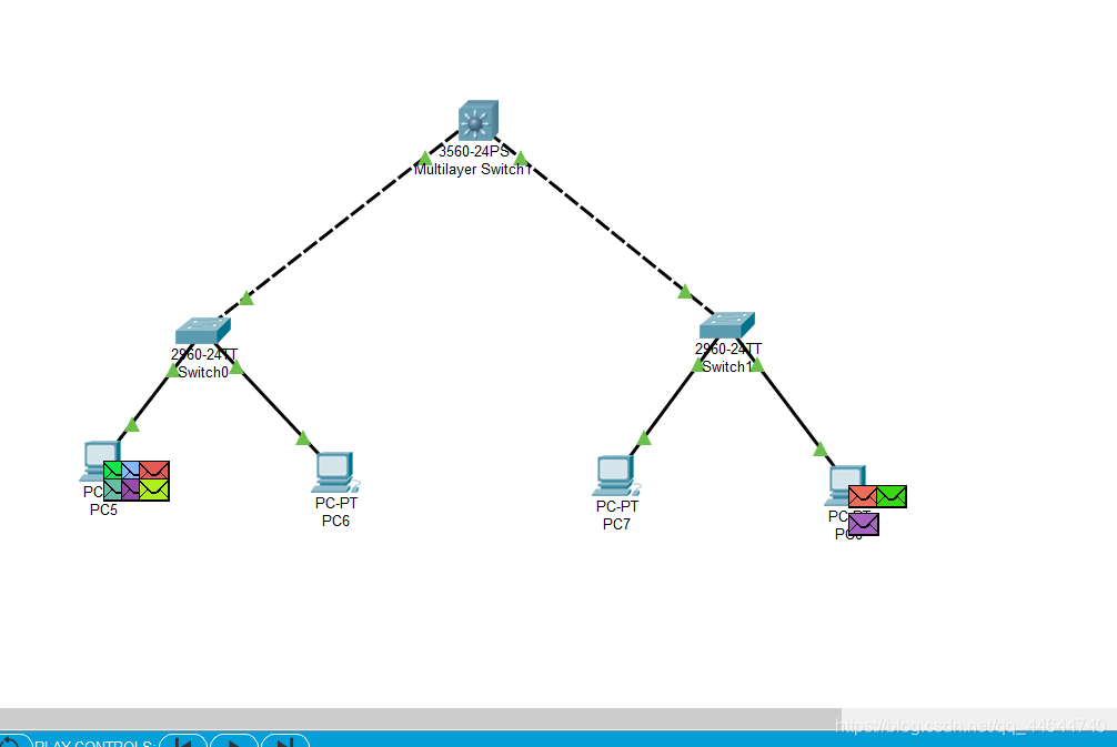
8. According to the previous method, add three PDU packets and send them from PC5 to PC6, PC7, and PC8. as follows: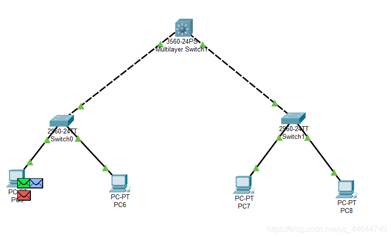
Then open the simulation observation, as follows: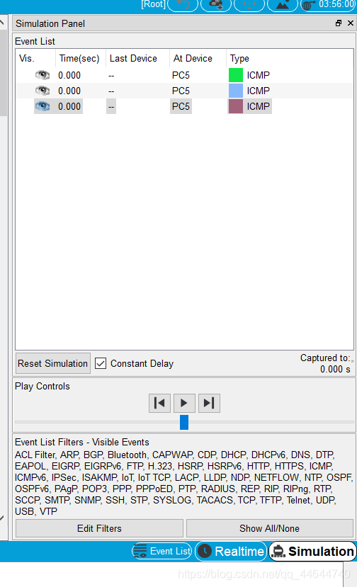
PC5 sends and PC6 receives successfully:

PC5 sends, PC7, PC8 cannot receive, as follows:

Question one
Can PC5 ping PC6, PC7, PC8?
Answer:
Can PC5 ping PC6, but cannot ping PC7 and PC8. This is because P5 and P6 are in the same subnet, but P7 and P8 are in a different subnet.
PDU transmission two
9. According to the previous method, add three PDU packets and send them from PC8 to PC5, PC6, and PC7. As follows:
Then open the simulation to observe, as follows: 
PC8 sent, PC7 received successfully completed:

PC8 sent, PC5, PC6 cannot receive, as follows:
Question two
Can PC8 ping PC5, PC6, PC7? why?
Answer:
Can PC8 ping PC7, but cannot ping PC5 and PC6. This is because P5 and P6 are in the same subnet, but P7 and P8 are in a different subnet.
PDU transmission three
10. First modify the subnet masks of PC5, PC6, PC7, and PC8 to 255.255.0.0, as follows:
11. Open the simulation again to observe the PDU transmission process, as follows:

At this time, it is found that all can be pinged.
Question three
Change the masks of the 4 PCs to 255.255.0.0, can they ping each other? why?
Answer:
You can ping through at this time. This is because although the four hosts are not in the same subnet, we have configured a gateway so that they can communicate with each other.
List of Layer 2 switch interface addresses
The Layer 2 switch is a plug-and-play multi-interface device. It has 3 processing methods for received frames: broadcast, forward and discard (please figure out when and what operation). ,
Then, to successfully forward, there must be an interface address list or MAC table in the switch, which is automatically obtained by the switch through learning.
Construct the same topology as the previous experiment.
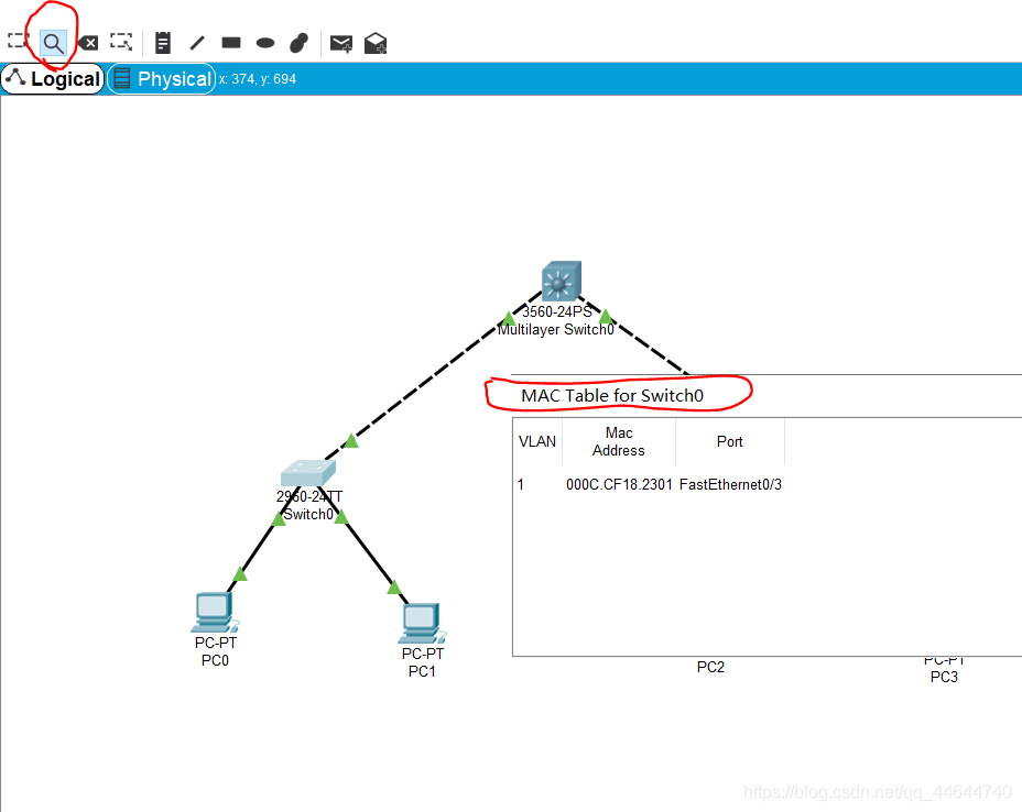
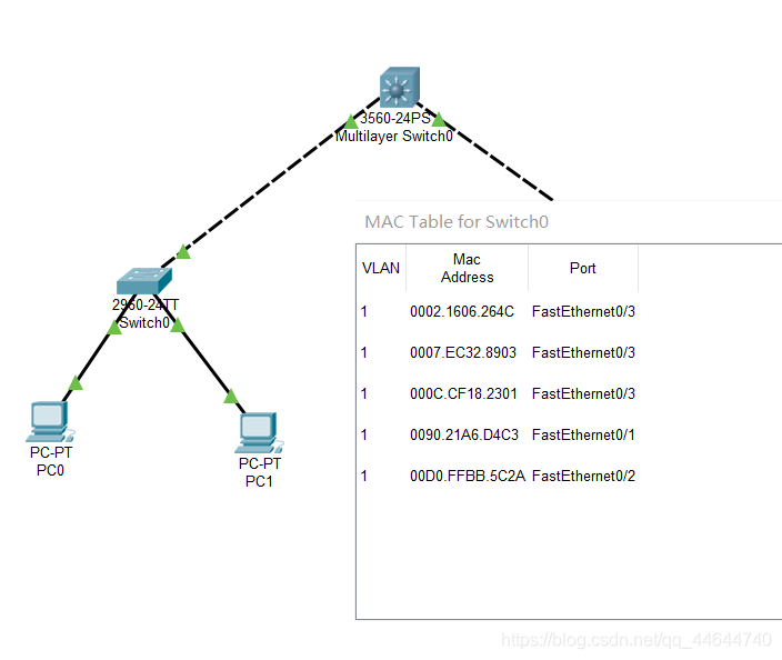
Configure the IP of each computer in the same subnet, use the magnifying glass in the toolbar to click on a switch 0, select MAC Table, you can see that the MAC table of the initial switch is empty, that is, it does not know how to forward frames, as follows :
PC0:192.168.0.1
PC1:192.168.0.2
PC2:192.168.0.3
PC3:192.168.0.4
Use PC0 to access (ping) PC1: 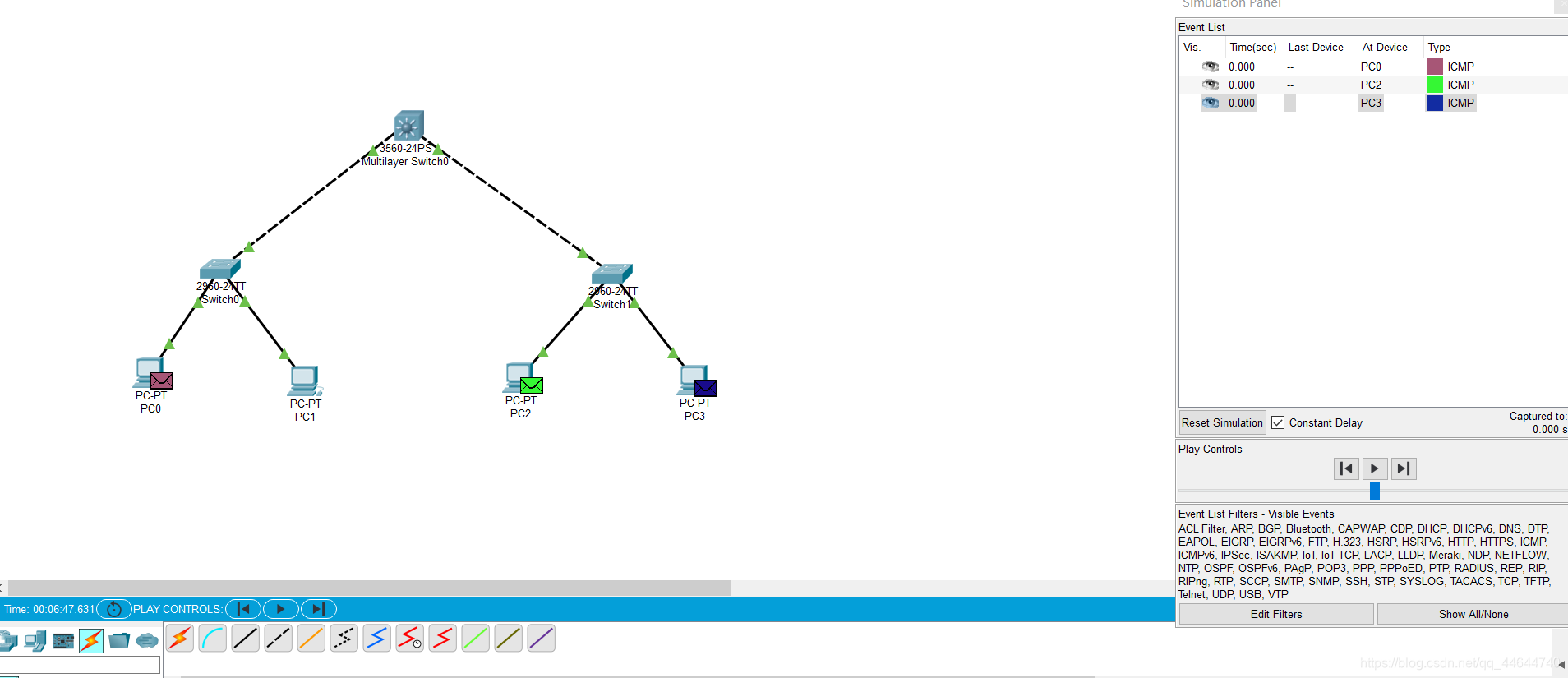

Check the MAC table of the switch again, there are corresponding records, as follows:
Question four
Do I need to configure a gateway for the network connected with a Layer 2 switch? why?
Answer: No, at this time, they are all connected to a switch and there is no gateway.
Spanning Tree Protocol
The switch will broadcast when the destination address is unknown or when it receives a broadcast frame. If there are loops/loops between switches, a broadcast loop storm will occur, which will seriously affect network performance.
The STP protocol running in the switch can avoid broadcast loop storms between switches.
Build a topology map
1. Place four switches according to the method between, as follows: 
2. Connect:
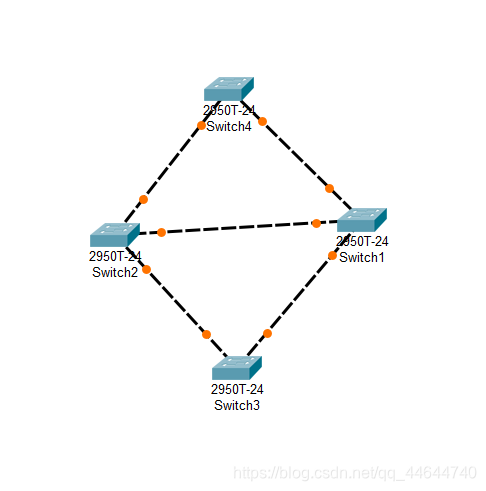

This is the initial state. We can see that there is a loop between the switches, which will cause broadcast frames to be transmitted cyclically, that is, a broadcast storm, which seriously affects network performance.
Subsequently, the switch will automatically block the redundant lines through the Spanning Tree Protocol (STP) to form a tree with a unique path, namely the spanning tree, with Switch4 as the root (which is the root switch has related policies) !
After a period of time, following the successful construction of the spanning tree with the STP protocol, the two interfaces of Switch5 are currently physically connected, but logically unconnected. They are in the Blocking state (orange) as shown in the figure below:
During network operation, if there is a problem with the physical connection between Switch1 and Switch2 (cut off the connection between Switch1 and Switch2), the spanning tree will automatically change. The previously Blocking interface under Switch2 is now active (green), but the upper interface is still in the Blocking state (orange). 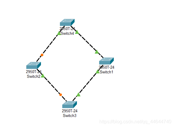

The STP protocol of the switch, that is, the Spanning Tree Protocol, always automatically guarantees that there will be no loops between the switches, thus forming a broadcast storm.
Preliminary router configuration
Simulate the connection between Chongqing Jiaotong University and Chongqing University.
Build a topology map
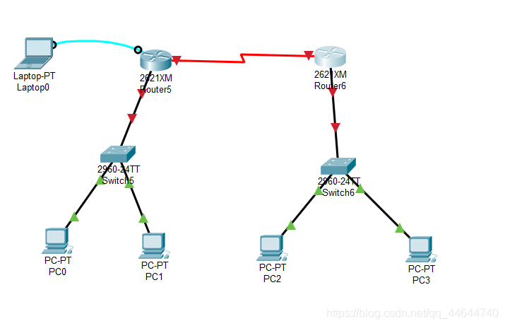
Explain 1:
Jiaotong University and Chongqing University are obviously two different subnets. Communication between different subnets needs to pass through a router.
Each interface of the router is at least one subnet. In the figure, we simply planned 3 subnets: the
router on the left is from Jiaotong University, and the switch is used to connect to the network of Jiaotong University. The network number is 192.168.1.0/24. The router interface is also the gateway of the Jiaotong University network, and the assigned IP is 192.168.1.1;
the router on the right is from Chongqing University, and the switch is used to connect to the network of Chongqing University, and the network number is 192.168.3.0/24. The router interface is also the network of Chongqing University. For the gateway, the assigned IP is 192.168.3.1; the
two routers are connected using a WAN interface, which is also a subnet, and the assigned network number is 192.168.2.0/24.
Note 2 In
reality, the connection between Jiaotong University and Chongqing University is remote. The connection is made either through the optical fiber interface of the router, or through the WAN interface, the so-called serial port (as shown in the topology diagram), and generally not through a twisted pair connection.
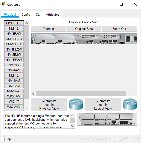
Let's take the connection through the WAN port of the router as an example for related configuration. Please note: The router we chose does not have a WAN module (named WIC-1T, etc.) by default. You need to turn off the router and add it, and then turn it on again.
Note 3:
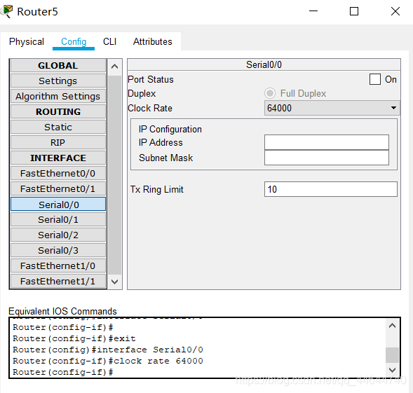
Attention should be paid to the DCE and DTE ends in the analog WAN connection (there is a prompt on the line when connecting, and the one with a clock mark is the DCE end. For the concepts of DCE and DTE, please refer to the relevant information.), the DCE end needs to be configured Clock frequency 64000;
Note 4 The
router has multiple command line configuration modes, each mode corresponds to a different prompt and corresponding authority;
Please pay attention to input configuration-related commands in the correct mode.
User mode: User mode
Privileged mode: Privileged mode
Global configuration mode: Global configuration mode
Interface mode: Interface configuration mode
Subinterface mode: Subinterface configuration mode
Note 5
In reality, it is obvious that the new router cannot be configured remotely. We must connect to the console interface of the router through the serial port of the notebook and perform the initial configuration (note that the bit rate is set to 9600) before remotely through the network. Configure it. This is also the purpose of the notebook connection drawn in the upper left of the above picture;
Note 6
In the CLI interface of the router, you can see that after the router is started successfully, because there is no configuration, you will be prompted whether to enter the initial configuration dialog (Would you like to enter the initial configuration dialog?). Because of the many steps, please select NO
For example, the preliminary configuration of the Jiaotong University router can be as follows: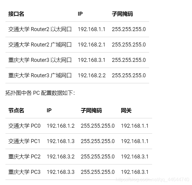
PDU transmission
Open the simulation to observe the PDU transmission process, as follows:

problem
Now the PCs and gateways in Jiaotong University can ping each other, and Chongqing University is similar. But it is not possible to ping major PCs from the PC of the National Chiao Tung University, and vice versa, that is, it cannot cross subnets. why?
Answer:
This is because the retransmission and the major server are not in the same subnet. If the two need to be pinged, the gateway needs to be configured.