A very good article I saw when I was learning serial communication, forward it to friends who need it.
1. Combing the experimental content
Firstly, the experiment will be described with the help of the serial port debugging assistant, so that you can get familiar with the whole process in combination with the code later. The whole experiment is actually to send data to the MCU through the serial port debugging assistant, and then the MCU will return the received data to the host computer and display it.
Simply speaking, the serial port debugging assistant is actually a bridge software for the communication between the upper computer and the lower computer. There are two main functions, which are also the two steps of this experiment:
1. Manually send data to the MCU for processing, that is, edit the data through the lower window of the serial port debugging assistant, and then click the send button to send the data to the MCU; 2. Accept the data sent by the MCU and display it to you, that is,
through the serial port debugging assistant above window to display the data sent back from the MCU to the host computer;
Regarding the serial port debugging assistant, you should also know:
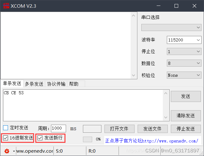
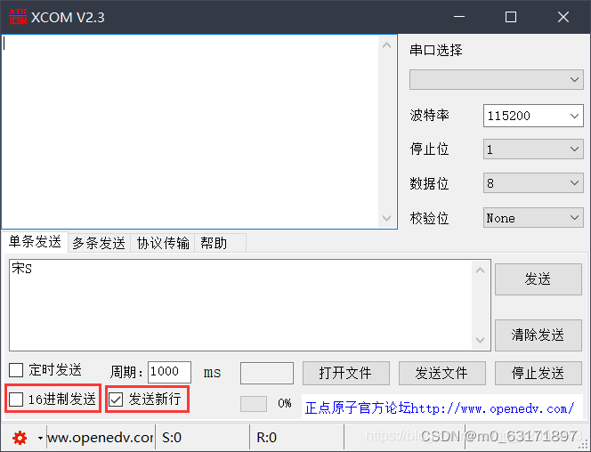
Sending English characters requires one character or 8 bits, and sending Chinese characters requires two characters or 16 bits. As shown in the figure above, sending the Chinese character "Song" is actually sending "CB (1100 1011) CE (1100 1110)" and sending the English character S is actually It is to send "53 (0101 0011)", there is not much difference in essence;
after checking the "send new line" below, XCOM will automatically add a carriage return (0X0D+0X0A) after the data you input to be sent ), if it is not checked, we need to press the Enter key after manually inputting "Song S". Only after clicking Send, the window above the debugging assistant can display it, because we A data receiving protocol is customized, that is, only when the received data ends with a carriage return (0X0D+0X0A), the serial port will recognize that the data has been received.
2. Understanding of the serial port interrupt function (custom data receiving protocol)
In the routine of the punctual atom, the relevant interrupt is enabled through the statement USART_ITConfig(USART1, USART_IT_RXNE, ENABLE). When the read data register is not empty, that is, when the microcontroller receives data, The interrupt function of serial port 1 will be triggered.
The core of the modified protocol is to define a 16-bit variable USART_RX_STA. The 0-13 bits of this variable are used to store the received data. The last 14 and 15 bits are used when the 14 and 15 bits receive da0x0d and 0x0a in sequence , these two positions are set to 1 in turn, as the flag bit for judging whether the data has been received.
The following is a more detailed code with comments I saw, and an example. By combining the two, you can understand the process and code well.
void USART1_IRQHandler(void)                	//串口1中断服务程序
	{
	u8 Res;     //定义unsigned char型字符Res

	if(USART_GetITStatus(USART1, USART_IT_RXNE) != RESET)
		//接收中断(接收到的数据必须是0x0d 0x0a结尾)
		//这里判断发送接收完成的依据就是串口数据0x0d 0x0a,
		//0x0d是CR(carriage return)回车的意思,光标回到最左边,
		//0x0a是LF(line feed)换行的意思,光标到达下一行,
		//但是在PC上回车和换行是在一起的就是按下回车按键
		//当然可以更改程序使用其他进行判断例如使用0x2a也就是*进行结束判断
		{
		Res =USART_ReceiveData(USART1);//(USART1->DR);
		//读取接收到的数据,存放到变量Res中
		if((USART_RX_STA&0x8000)==0)
			//判断接收是否未完成
			//接收完成未清除标志位,还是会不断进入到接收中断,所以使用标志进行判断,
		  //当接收完成便不会跳入到判断,从而不执行任何指令,空等待
			//使用条件判断是否已经接收完数据,这里判断接收完的依据就是收到了0x0a;
			//具体判断在后面
			{
			if(USART_RX_STA&0x4000)
			//如果接收到了0x0d,那么再进一步执行是否接收到0x0a的判断
				{
				if(Res!=0x0a)USART_RX_STA=0;
			//没有接收到0x0a那么说明,数据未正确传输或者接收错误,重新开始判断,
			//但是这里没有将接收到的数据进行清空,也没有退出接收中断,此程序只是从头开始执行接收判断
				else USART_RX_STA|=0x8000;
			//接收完成了,收到了0x0a那么标志位USART_RX_STA将会变成0x8000,将不再进行数据检测与存储
				}
			else
				//还没收到0X0D,说明数据还未发送结束继续进行数据的检测与存储
				{
				if(Res==0x0d)USART_RX_STA|=0x4000;
				//收到了数据0x0d,标志位USART_RX_STA变成0x4000
				else
					{
				//如果没有接收到数据0x0d,执行判断是否存储数组已满,已满则重新开始接收
					USART_RX_BUF[USART_RX_STA&0X3FFF]=Res ;
				//将接收到的数据写进数组,标志位USART_RX_STA与上0X3FFF清除前两位以防止标志位与8000和4000冲突
					USART_RX_STA++;
				//数组地址加一,向后排
					if(USART_RX_STA>(USART_REC_LEN-1))USART_RX_STA=0;
				//接收数据错误,超出数组大小,又开始接收向数组重新写
					}
				}
			}
     }

}
Suppose the data we send is "abcd" and sent to the MCU after the serial port debugging assistant adds 0X0D+0X0A, that is, the data to be accepted by the MCU is "abcd"+"0X0D+0X0A"
(1) When "a" is received, the read register is not empty, RXNE is 1, and the serial port interrupt processing function is entered for the first time. We first judge whether the connection is because USART1 has received an interrupt generated by data. If so, USART1 will accept the interrupt. The received one-bit data "a" is stored in the variable Res (Res = "a")
if(USART_GetFlagStatus(USART1, USART_IT_RXNE) != RESET)2) Then we judge whether the received series of data has not been received (ie). (Of course not, we still have three data b, c, and d that have not been received). At this time, the value of USART_RX_STA—the variable that realizes message transmission among all functions is still 0, and after being combined with 0x8000, it is 0, then the inner function of the if statement is executed.
if((USART_RX_STA&0x8000)==0) //接收未完成3) After entering the inner statement of the if statement, the judgment statement is as follows. Here, it is judged whether the 14th bit of USART_RX_STA is 1. If we receive a carriage return, that is, 0x0d, then the 14th bit of USART_RX_STA will be set to 1. When we receive the first data a, USART_RX_STA is of course still 0, (the b, c, d, and 3 data behind us have not been received yet, of course we will not receive 0x0d) The phase AND of USART_RX_STA and 0x400 is 0, The judgment statement is false, and the following else statement is executed.
if(USART_RX_STA&0x4000)//接收到了0x0d(4) The inner statement of the else statement is an if-else statement
if(Res==0x0d)USART_RX_STA|=0x4000; I won’t go into details here, what we receive is data a, but we haven’t received 0x0d yet, execute the else statement.
USART_RX_BUF[USART_RX_STA&0X3FFF]=Res ; // 0x3ff = 0011 1111 1111 1111

USART_RX_STA++;

if(USART_RX_STA>(USART_REC_LEN-1))USART_RX_STA=0;//接收数据错误,重新开始接收
Bit0~bit13 of USART_RX_STA represent the number of valid data received, where the value of USART_RX_STA is still 0, USART_RX_STA & 0X3FFF = 0, and then USART_RX_BUF[USART_RX_STA&0X3FFF]=Res, which means to store the data in Res to USART_RX_BUF[0] In, and USART_RX_STA increments by 1.
At this time, USART_RX_STA = 1, so that after receiving the next data b, USART_RX_STA&0X3FFF = 1, store b into USART_RX_BUF[1], and continue to loop until we receive 0x0d (Res = 0x0d).
We can find the following code from the above program:
else //还没收到0X0D
				{
				if(Res==0x0d)USART_RX_STA|=0x4000; //再次判断这次接收到的是不是0x0d
When 0x0d is received and the program executes to this step, USART_RX_STA = 4, and the if statement is established at this time, execute USART_RX_STA|=0x4000, that is, 0000 0000 0000 0100 | 0100 0000 0000 0000 = 0100 0000 0000 0100, we can clearly see Bit13~0 is 4, which means that 4 data (a, b, c, d) have been received, and the 14th bit is 1, because the data 0x0d has been received, and it is also matched with the table given above, and then the program goes to Next execution, received 0x0d (carriage return), then the next one is to receive 0x0a (line feed), Res = 0x0a:
if(USART_RX_STA&0x4000)//接收到了0x0d     0100 0000 0000 0000
				{
				if(Res!=0x0a)USART_RX_STA=0;//接收错误,重新开始--接收到了0X0d但是没有接受到0x0a
				else USART_RX_STA|=0x8000;	//接收完成了--0x0d后面是0x0a
				}
The first judgment statement here, if(USART_RX_STA&0x4000), is of course true, because Res = 0x0a, then execute the else statement USART_RX_STA|=0x8000, that is, 0100 0000 0000 0100 | 1000 0000 0000 0000 = 1100 0000 0000 0100. At this point, it means that this string of data has been completely received USART_RX_STA = 1100 0000 0000 0100, the highest bit is 1: it means that 0x0a has been received, the fourteenth bit is 1: it means that 0x0d has been received, and the 0th bit is The 13th bit is 4, which means that 4 bits of valid data (a, b, c, d) have been received
3. Understanding of the main function
The main function is as follows, and the general execution flow is:
int main(void)
{

	u8 t;
	u8 len;
	u16 times=0;
	NVIC_PriorityGroupConfig(NVIC_PriorityGroup_2);//设置系统中断优先级分组2
	delay_init(168);		//延时初始化
	uart_init(115200);	//串口初始化波特率为115200
	LED_Init();		  		//初始化与LED连接的硬件接口
	while(1)
	{
		if(USART_RX_STA&0x8000)
		{
			len=USART_RX_STA&0x3fff;//得到此次接收到的数据长度
			printf("\r\n您发送的消息为:\r\n");
			while(USART_GetFlagStatus(USART1,USART_FLAG_TC)!=SET);
			for(t=0;t<len;t++)
			{

				USART_SendData(USART1, USART_RX_BUF[t]);         //向串口1发送数据
				while(USART_GetFlagStatus(USART1,USART_FLAG_TC)!=SET);//等待发送结束
			}
			printf("\r\n\r\n");//插入换行
			USART_RX_STA=0;
		}else
		{
			times++;
			if(times%300==0)
			{
				printf("\r\nALIENTEK 探索者STM32F407开发板 串口实验\r\n");
				printf("正点原子@ALIENTEK\r\n\r\n");
			}
			if(times%200==0)printf("请输入数据,以回车键结束\r\n");
			if(times%30==0)LED0=!LED0;//闪烁LED,提示系统正在运行.
			delay_ms(10);
		}
	}
}
1. Complete the relevant settings of the serial port, enable the corresponding interrupt, and the initialization process, and then enter the while waiting;
2. When the data to be sent is input in the serial port debugging assistant's thinking window, and click send, when the microcontroller starts to receive data It will trigger the interrupt function USART1 IRQHandler ( ) to receive the data and finally store it into the buffer RX_BUF_USART, and its life in usart.h is extern u8 USART_RX_BUF[USART_REC_LEN]. Among them, USART_REC_LEN=200
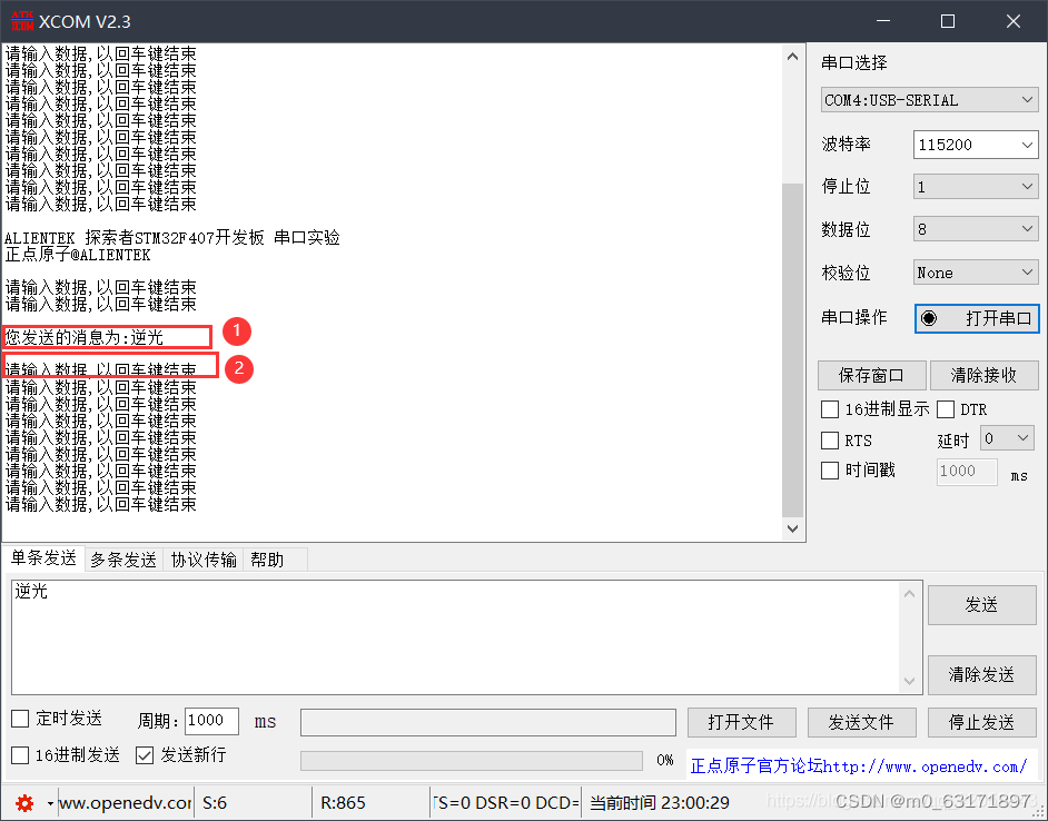
3. Use the language if (USART RX STA&0x8000) to judge whether the data has been accepted and stored in the buffer array RX_BUF_USART. If it is completed, use the redirected printf function to send the statement "\r\nYou sent The message is:\r\n", the following icon number 1 area (the experimental phenomenon here is abnormal, there will be an explanation later) and then send the data in the cache RX_BUF_USART to the host computer through the USART_SendData() function through the for loop, and send it to the host The data of the computer will be displayed on the serial debugging assistant. After all the data is sent, send "\r\n\r\n" to the host computer again through the printf function, that is, the window cursor on the serial port debugging assistant moves up and down two lines based on the original position. It is shown in area 2 of the icon below.
4. When the data has not been received or sent to the MCU, the MCU will send "\r\nALIENTEK Explorer STM32F407 Development Board Serial Port Experiment\r\n", "Punctual atom
Note: The redirected printf() function essentially sends data to the host computer through USART_SendData(), and the "\r\n" sent here and the "\r\n" in the interrupt function need to be used as the acceptance completion flag "(0X0D+0X0A) is just an escape character that simply means a newline. After receiving it, the upper computer will move the cursor down two lines. Visually, it is an empty line displayed on the serial port debugging assistant.
4. Experimental anomalies and solutions.
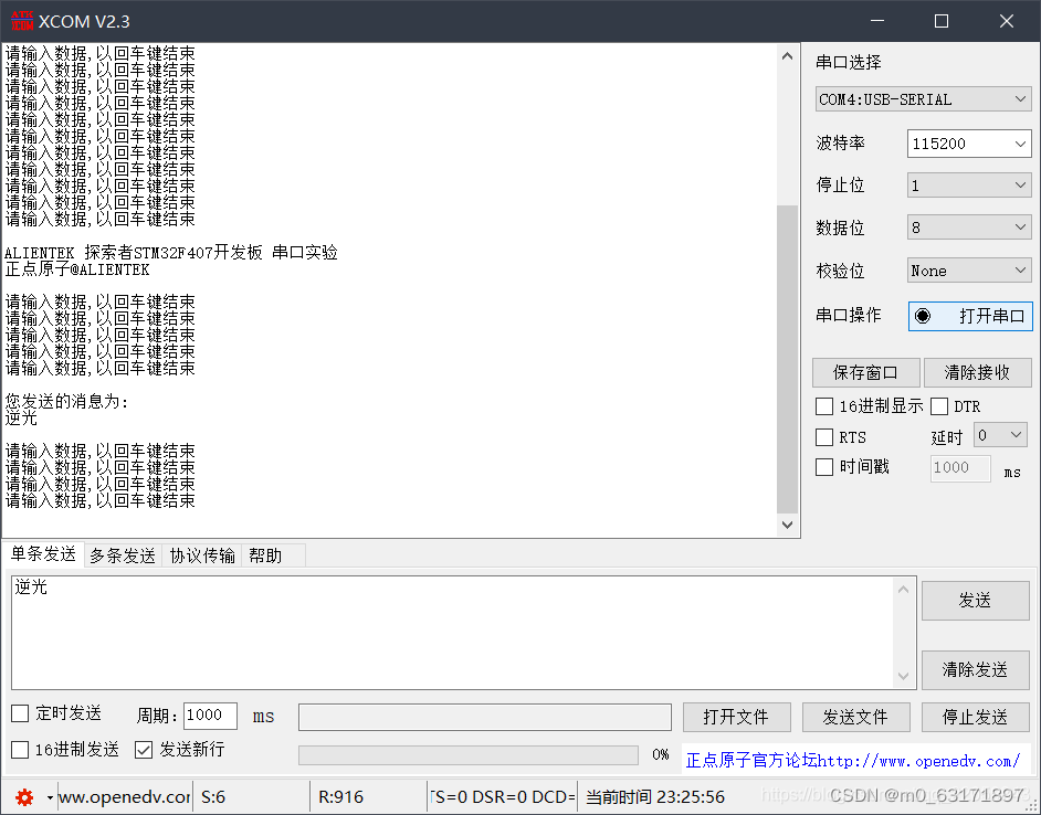
It is mentioned above that there is an abnormal experimental phenomenon in the area of the picture label 1, that is, the result displayed by the single-chip microcomputer using the printf("\r\nThe message you sent is:\r\n") statement The "\r\n" at the end of the statement does not work, that is, the "backlight" is displayed after the cursor moves to the next line.
The reason for this phenomenon is that the sending of "\r\n" in the printf statement is not completed, and the register is overwritten by the data to be sent later. The solution is to add a while in front of USART_SendData(USART1, USART_RX_BUF[t]); (USART_GetFlagStatus(USART1,USART_FLAG_TC)!=SET);//Waiting for the end of sending
for(t=0;t<len;t++)
			{
				while(USART_GetFlagStatus(USART1,USART_FLAG_TC)!=SET);
				USART_SendData(USART1, USART_RX_BUF[t]);         //向串口1发送数据
				while(USART_GetFlagStatus(USART1,USART_FLAG_TC)!=SET);//等待发送结束
			}
I have tried to solve the problem by using delay after the printf statement, but only the first time it can be displayed normally, and when it is sent again later, the actual data will have the problem of garbled characters.
5. USART-FLAG-TXE and USART-FLAG-TC flags
I think the use of these two flags should be strictly separated, as an additional knowledge record:
USART-FLAG-TXE transmit buffer empty flag: It means that data can be written to the data register, but it does not mean that the code data transmission is completed.
USART-FLAG-TC sending completion flag: This means that the data transmission of the USART in the buffer is completed, that is, the slave has received the data.
The difference between these two flags is that they respectively indicate the completion of the data in two different stages during the transmission process. TXE indicates that the data is taken from the transmission buffer and transferred to the shift register. At this time The send buffer is empty and new data can be added to it. The TC indicates that the data that is finally put into the sending buffer has been transferred from the shift register to the sending signal line Tx. Therefore, the flag that determines that the data is finally sent is TC, not IXE.