OSPF简介
OSPF是一个内部网关协议,用于在单一自治系统内决策路由。是一种典型的链路状态(Link-state)的路由协议。
OSPF通过路由器之间通告网络接口的状态来建立链路状态数据库,生成最短路径树,每个OSPF路由器使用这些最短路径构造路由表。在一个AS(Autonomous System,自治系统)中,所有的OSPF路由器都维护一个相同的描述这个AS结构的数据库,该数据库中存放的是路由域中相应链路的状态信息。
作为一种链路状态的路由协议,OSPF将链路状态组播数据LSA(Link State Advertisement)传送给在某一区域内的所有路由器。区域内的路由器收到LSA后,会将其放入LSDB(link state database,链路数据库)中,由其计算出最优的路径放入路由表中。
OSPF主要根据cost值来选择路径,计算式为:${10}^{8}$÷接口带宽。OSPF会进行周期,每30min更新一次,是针对于每一条LSA的更新,我们称这种更新方式为错峰出行。
OSPF同样具有邻居的概念,通过向邻居发送HELLO包来维系邻居关系。每10s发一次,若40s内未收到邻居的应答则认为邻居死亡。
OSPF报文直接封装在IP报头中发送。
OSPF几种版本:
- version 1,用于实验环境下
- version 2,基于IPv4的版本
- version 3,基于IPv6的版本
OSPF的三张表:
1.邻居表。show ip ospf neighbor
2.LSDB表。show ip ospf database
3.路由表。show ip route ospf
OSPF区域特性:
1.减小了路由表大小。
2.本地拓扑的改变只会对本区域产生影响。
3.明细的LSA的传递只会停留在区域的边界ABR(区域边界路由器area border router)。
ASBR:自治系统边界路由器(autonomous system boundary router),指连接两个运行不同协议的网络的路由器。
4.具有层次化的网络。
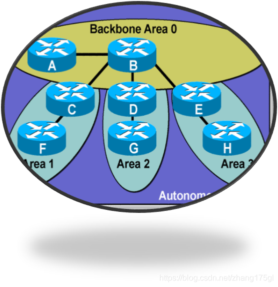
需要注意的是,骨干区域内(area 0)的路由器都是骨干路由器。
同时连接着骨干区域和常规区域的路由器一定是ABR(区域边界路由器)。
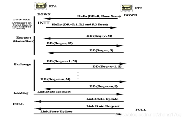
OSPF的几个状态
1.Down:此状态还没有与其他路由器交换信息。首先从其ospf接口向外发送hello分组,还并不知道DR(若为广播网络)和任何其他路由器。发送hello分组时使用组播地址224.0.0.5。
2.init状态: 一方收到了另一方的hello。但在这个hello包中还看不到自己是对方的邻居,这种状态叫做init状态。
3..two-way状态: 双方的hello已经交换完成,建立了邻居关系(注意区别于邻接关系),dr,bdr选举成功,若两端都是drother路由器则会一直停留在这个状态。
4.Exstart状态: 交换LSA之前,两端路由器会选择一个主从关系,确定由谁来先发起数据(DBD,LSR等),router-id较大者成为主路由器,先发送,选举主从关系的状态叫做exstart状态。
关于router-id:router-id在ospf中,起到了一个表明身份的作用,不同的router-id表明了在一个ospf进程中不同路由器的身份。一般手动配置时会选择路由器上的loopback接口的ip地址作为router-id。 如果没有loopback接口,那么可以不进行人为配置,系统自动选择物理接口上最大的ip地址。
注:router-id不可配置为0.0.0.0和255.255.255.255 。
5.Exchange状态: 交换DBD的过程,DBD相当于一个路由器自己的链路状态数据库的目录,对方收到DBD根据目录来索要自己需要的信息从而发送LSR
6.Loading状态: 邻居收到了对方发来的LSR,回复对方索要的信息LSU,这是一个学习的过程,叫做loading状态。
7.Full状态: 完全邻接状态,数据库已经同步,网络收敛完成,就是最后达到的正常的状态
8.Attempt状态: 这是在特殊网络条件下才有的状态,就是不支持广播的网络(非广播网络),以太网是没有的,因为ospf需要使用组播发送hello,所以在这种网络环境下,必须要指定使用单播来发送hello,这种状态叫做attempt状态。
邻居状态机:
LSDB的建立过程: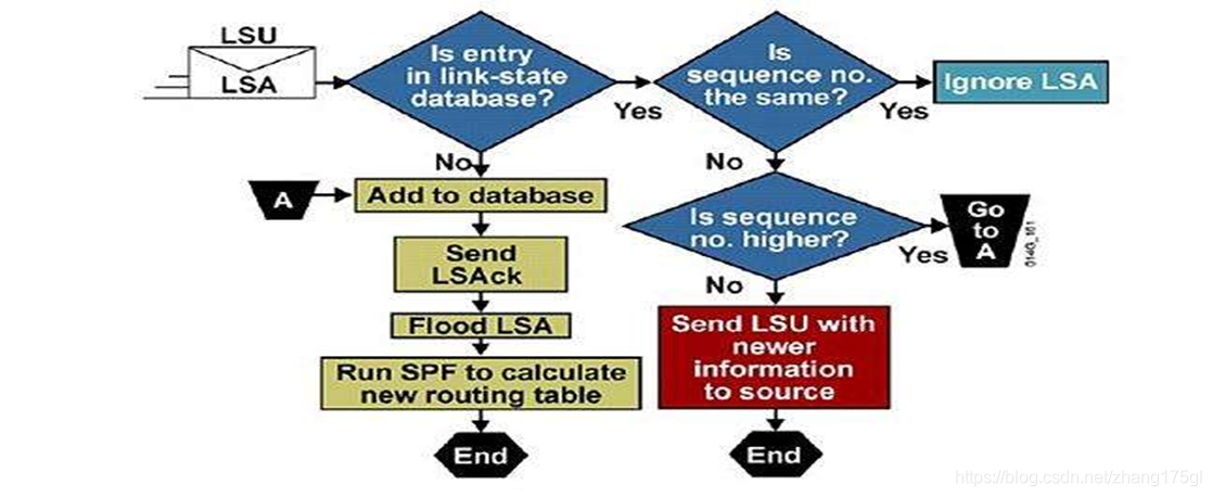
OSPF几种数据包图解: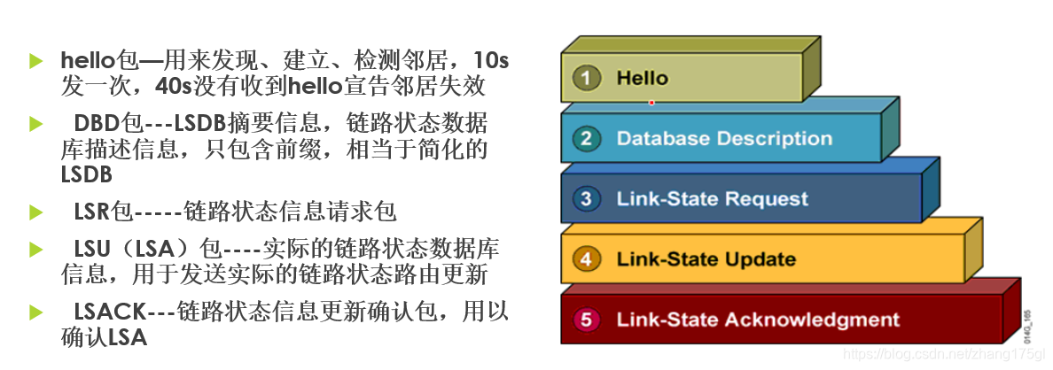
OSPF五种网络类型
1.点到点网络
通常指早期的帧中继网络serial或T1网络,亦即专线网络。
是连接单独的一对路由器的网络,因为链路上只有两台路由器,故而跳过了选举BR和BDR阶段,直接进入到FULL状态。在这种网络上,OSPF包的目标地址使用的是224.0.0.5,这个组播地址称为AllSPFRouters.
这种网络收敛速度极快,因此在实际应用中,若是两个不同的自治系统之间的路由器设备未连接交换机的话,可以将这两个路由器设置为点到点网络来加速收敛。
Route(config)#interface s0/0
Route(config-if)#ip ospf network point-to-point
2.广播型网络
如以太网,Token Ring和FDDI,这样的网络上会选举一个DR和BDR,DR/BDR发送的OSPF包的目标地址为224.0.0.5,运载这些OSPF包的帧的目标MAC地址为0100.5E00.0005;而除了DR/BDR以外的OSPF包的目标地址为224.0.0.6,这个地址叫AllDRouters.
3.非广播型(NBMA)网络
如X.25,Frame Relay,和ATM,不具备广播的能力,因此邻居要人工来指定,在这样的网络上要选举DR和BDR,OSPF包采用unicast的方式
4.点到多点网络
是NBMA网络的一个特殊配置,可以看成是点到点链路的集合. 在这样的网络上不选举DR和BDR.
5.虚链接(virtual link)
OSPF包以unicast的方式发送
六类常见的LSA
将LSA进行分类的目的是为了方便优化,减小路由表的大小,让各类的LSA信息只在自己的区域内进行传递,从而节省设备的资源。
show ip ospf database可查看链路状态数据库。
一类LSA(区域内的条目O)
Router Link States:区域内的每个路由器都将产生Router LSA,这种LSA只在本区域内传播,描述了该路由器所有的链路和接口,状态和开销。通告的是自己。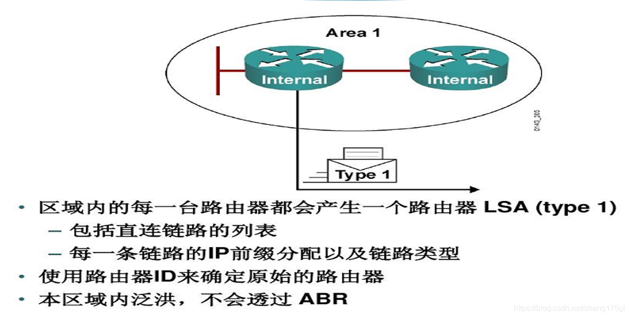
二类LSA(常见但不重要,只是展示出谁是DR)
Network LSA:在每个多路访问网络中,DR都会产生这种Network LSA,它只在产生这条Network LSA的区域泛洪,描述了所有和它相连的路由器(包括DR本身)。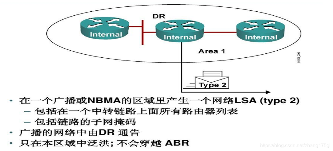
三类LSA(区域间的LSA---O IA)
Network Summary LSA :由ABR路由器始发,用于通告该区域外部的目的地址。当其他的路由器收到来自ABR的Network Summary LSA以后,不会运行SPF算法,只简单的加上到达那个ABR的开销和Network Summary LSA中包含的开销,通过ABR,到达目标地址的路由和开销一起被加进路由表里。这种发送区域间的LSA的路由条目,在链路状态数据库中体现为O IA条目。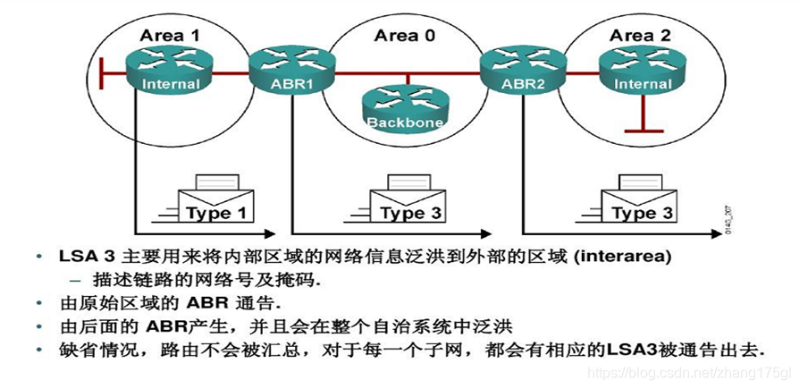
四类LSA(常见但不重要,只是展示谁是ASBR)
ASBR Summary LSA:由ABR发出,ASBR汇总LSA除了所通告的目的地是一个ASBR而不是一个网络外,其他同NetworkSummary LSA。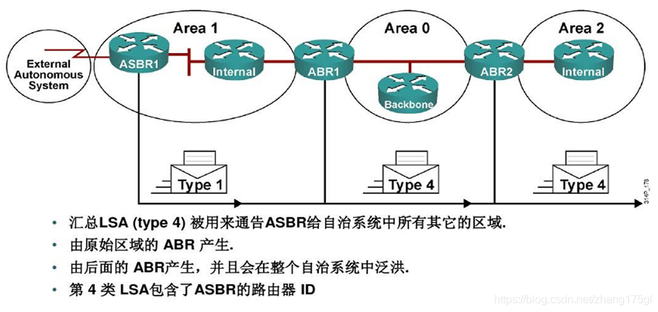
五类LSA(自治系统外部的LSA ---OE)
AS External LSA:发自ASBR路由器。用来通告来自OSPF自治系统外部的网络,或者OSPF自治系统外部的缺省路由的LSA。这种LSA将在全AS内泛洪。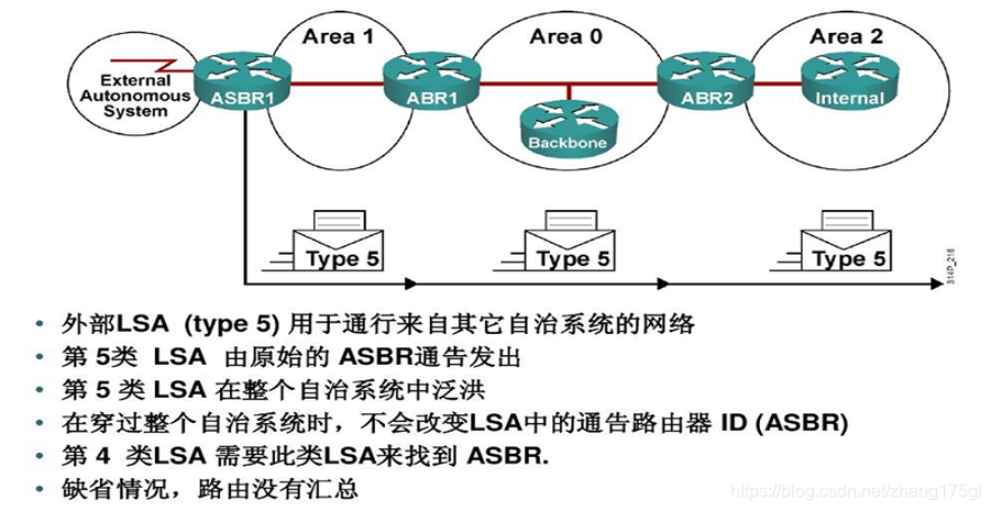
七类LSA(NSSA,非完全末节区域)
NSSA External LSA:来自非完全末节区域(not-so-stubby area)内ASBR路由器始发的LSA通告。它只在NSSA区域内泛洪,这是与LSA-Type5的区别。
OSPF路由类型
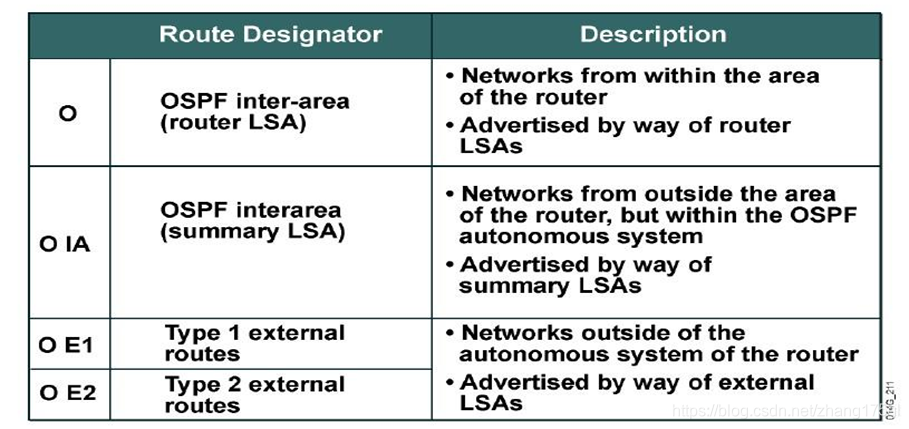
1 、O 域内路由
2 、O IA 域间路由
3 、O E1 域外路由,会累加metric值(默认20)
4 、O E2 域外路由,不累加metric值(默认20),由外部重分布进来默认使用OE2。
重分布直连配置命令:
R(config)#router ospf 100
//若不选择则默认为O E2
R(config-router)#redistribute connected subnets metric-type 1或2
O E1和O E2的区别:
它们代表的是外部路由1和外部路由2,它们的区别就在于是否加内部路由(度量花销)。默认是O E2就是不加内部路由,假设网络只有一个出口,那么使用OE1和OE2都一样;
A、如果有多个ASBR宣告一条到达同一外部AS的外部路由时候用只需要比较域外部开销,只需考虑外部开销更小就可以了,不需要考虑内部开销。所以优先选择O E2。
B、单出口(ASBR),计不计算域内开销已经没有意义,所以默认O E2。
C、如果我们只有一个出口那么O E2就能帮我们解决所有问题,如果我们有多个出口这时我们可以使用O E1,它能够让我们在做路由决策的时候变得更加精确。因此多出口,建议用O E1。
cost值的比较:
O >O IA > O E1 >O E2
接口下修改cost值:
R(config-if)#ip ospf cost value
在实际应用中,若接口的带宽高于100M,其默认cost均为1,为确保路由计算的准确性,应当考虑使用以下命令:
R(config-router)#auto-cost reference-bandwidth
OSPF路由汇总
基本配置;
R1
R1(config)#interface loopback 0
R1(config-if)#ip address 1.1.1.1 255.255.255.0
R1(config-if)#exit
R1(config)#interface f0/0
R1(config-if)#ip address 12.1.1.1 255.255.255.0
R1(config-if)#no shutdown
R1(config-if)#exit
R1(config)#interface range f0/0 , loopback 0
R1(config-if-range)#ip ospf 100 area 1
R1(config-if-range)#exit
R1(config)#router ospf 100
R1(config-router)#router-id 1.1.1.1
R1(config-router)#network 1.1.1.0 0.0.0.255 area 0
R1(config-router)#network 12.1.1.0 0.0.0.255 area 0
R1(config-router)#exit
R2
R2(config)#interface f1/0
R2(config-if)#ip address 23.1.1.1 255.255.255.0
R2(config-if)#no shutdown
R2(config-if)#exit
R2(config)#interface f0/0
R2(config-if)#ip address 12.1.1.2 255.255.255.0
R2(config-if)#no shutdown
R2(config-if)#exit
R2(config)#interface loopback 0
R2(config-if)#ip address 2.2.2.2 255.255.255.0
R2(config-if)#no shutdown
R2(config-if)#exit
R2(config)#router ospf 100
R2(config-router)#router-id 2.2.2.2
R2(config-router)#network 2.2.2.0 0.0.0.255 area 0
R2(config-router)#network 12.1.1.0 0.0.0.255 area 0
R2(config-router)#network 23.1.1.0 0.0.0.255 area 1
R2(config-router)#exit
R2(config)#interface range f0/0 , loopback 0
R2(config-if-range)#ip ospf 100 area 1
R2(config-if-range)#exit
R2(config)#interface range f1/0 , loopback 0
R2(config-if-range)#ip ospf 100 area 0
R2(config-if-range)#exit
R3
R3(config)#interface f0/0
R3(config-if)#ip address 23.1.1.2 255.255.255.0
R3(config-if)#no shutdown
R3(config-if)#exit
R3(config)#interface loopback 0
R3(config-if)#ip address 3.3.3.3 255.255.255.0
R3(config-if)#no shutdown
R3(config-if)#exit
R3(config)#interface f1/0
R3(config-if)#ip address 34.1.1.1 255.255.255.0
R3(config-if)#no shutdown
R3(config-if)#exit
R3(config)#router ospf 100
R3(config-router)#router-id 3.3.3.3
R3(config-router)#network 3.3.3.0 0.0.0.255 area 0
R3(config-router)#network 23.1.1.0 0.0.0.255 area 0
R3(config-router)#network 34.1.1.0 0.0.0.255 area 2
R3(config-router)#exit
R3(config)#interface range f0/0 , loopback 0
R3(config-if-range)#ip ospf 100 area 0
R3(config-if-range)#exit
R3(config)#interface range f1/0 , loopback 0
R3(config-if-range)#ip ospf 100 area 2
R3(config-if-range)#exit
R3(config)#interface loopback 1
R3(config-if)#ip address 172.16.1.1 255.255.255.0
R3(config-if)#no shutdown
R3(config-if)#exit
R3(config)#interface loopback 2
R3(config-if)#ip address 172.16.2.1 255.255.255.0
R3(config-if)#no shutdown
R3(config-if)#exit
R3(config)#interface loopback 3
R3(config-if)#ip address 172.16.3.1 255.255.255.0
R3(config-if)#no shutdown
R3(config-if)#exit
R3(config)#interface range loopback 1 - 3
R3(config-if-range)#ip ospf 100 area 0
R3(config-if-range)#exit
R4
R4(config)#interface loopback 0
R4(config-if)#ip address 4.4.4.4 255.255.255.0
R4(config-if)#no shutdown
R4(config-if)#exit
R4(config)#interface f0/0
R4(config-if)#ip address 34.1.1.2 255.255.255.0
R4(config-if)#no shutdown
R4(config-if)#exit
R4(config)#router ospf 100
R4(config-router)#router-id 4.4.4.4
R4(config-router)#network 34.1.1.0 0.0.0.255 area 2
R4(config-router)#network 4.4.4.0 0.0.0.255 area 2
R4(config-router)#exit
R4(config)#interface range f0/0 , loopback 0
R4(config-if-range)#ip ospf 100 area 2
R4(config-if-range)#exit
R4(config)#interface loopback 1
R4(config-if)#ip address 192.16.1.1 255.255.255.0
R4(config-if)#no shutdown
R4(config-if)#exit
R4(config)#interface loopback 2
R4(config-if)#ip address 192.16.2.1 255.255.255.0
R4(config-if)#no shutdown
R4(config-if)#exit
R4(config)#interface loopback 3
R4(config-if)#ip address 192.16.3.1 255.255.255.0
R4(config-if)#no shutdown
R4(config-if)#exit
基础配置如上
现在我们先来在R1上查看OSPF的路由表,以便与后续的操作结果作对比。
R1(config)#do show ip route ospf
     34.0.0.0/24 is subnetted, 1 subnets
O IA    34.1.1.0 [110/3] via 12.1.1.2, 00:38:43, FastEthernet0/0
     2.0.0.0/32 is subnetted, 1 subnets
O IA    2.2.2.2 [110/2] via 12.1.1.2, 00:46:23, FastEthernet0/0
     3.0.0.0/32 is subnetted, 1 subnets
O IA    3.3.3.3 [110/3] via 12.1.1.2, 00:38:38, FastEthernet0/0
     4.0.0.0/32 is subnetted, 1 subnets
O IA    4.4.4.4 [110/4] via 12.1.1.2, 00:38:33, FastEthernet0/0
     23.0.0.0/24 is subnetted, 1 subnets
O IA    23.1.1.0 [110/2] via 12.1.1.2, 00:46:23, FastEthernet0/0
     172.16.0.0/32 is subnetted, 3 subnets
O IA    172.16.1.1 [110/3] via 12.1.1.2, 00:22:12, FastEthernet0/0
O IA    172.16.3.1 [110/3] via 12.1.1.2, 00:22:12, FastEthernet0/0
O IA    172.16.2.1 [110/3] via 12.1.1.2, 00:22:12, FastEthernet0/0
O E2 192.16.1.0/24 [110/20] via 12.1.1.2, 00:03:03, FastEthernet0/0
O E2 192.16.2.0/24 [110/20] via 12.1.1.2, 00:00:40, FastEthernet0/0
O E2 192.16.3.0/24 [110/20] via 12.1.1.2, 00:00:08, FastEthernet0/0
OSPF的路由汇总操作均需在进程下做。
1.域间汇总:OSPF自治系统内部的汇总,汇总操作需要在ABR上做。
R1要收到路由汇总,因为路由是从R2的f0/0端口发出并汇总的,所以应当在R2上进行配置。
R2(config)#router ospf 100
//为area 0做域间汇总汇总
R2(config-router)#area 0 range 172.16.0.0 255.255.252.0
R2(config-router)#exit
此时,R1上查看OSPF路由表,可看到路由已经汇总:
R1(config)#do show ip route ospf
     34.0.0.0/24 is subnetted, 1 subnets
O IA    34.1.1.0 [110/3] via 12.1.1.2, 01:27:21, FastEthernet0/0
     2.0.0.0/32 is subnetted, 1 subnets
O IA    2.2.2.2 [110/2] via 12.1.1.2, 01:35:02, FastEthernet0/0
     3.0.0.0/32 is subnetted, 1 subnets
O IA    3.3.3.3 [110/3] via 12.1.1.2, 01:27:16, FastEthernet0/0
     4.0.0.0/32 is subnetted, 1 subnets
O IA    4.4.4.4 [110/4] via 12.1.1.2, 01:27:12, FastEthernet0/0
     23.0.0.0/24 is subnetted, 1 subnets
O IA    23.1.1.0 [110/2] via 12.1.1.2, 01:35:02, FastEthernet0/0
     172.16.0.0/22 is subnetted, 1 subnets
O IA    172.16.0.0 [110/3] via 12.1.1.2, 00:01:02, FastEthernet0/0
O E2 192.16.1.0/24 [110/20] via 12.1.1.2, 00:00:57, FastEthernet0/0
O E2 192.16.2.0/24 [110/20] via 12.1.1.2, 00:00:57, FastEthernet0/0
O E2 192.16.3.0/24 [110/20] via 12.1.1.2, 00:00:57, FastEthernet0/02.域外汇总:OSPF自治系统外部的汇总,汇总操作需要在ASBR上做。
同域间汇总一样,外部的路由条目由ASBR路由器汇总后发出。以R4为例:
R4(config)#router ospf 100
R4(config-router)#summary-address 192.16.0.0 255.255.252.0
R4(config-router)#exit
此时R1上查看OSPF路由表如下所示:
R1(config)#do show ip route ospf
     34.0.0.0/24 is subnetted, 1 subnets
O IA    34.1.1.0 [110/3] via 12.1.1.2, 01:34:10, FastEthernet0/0
     2.0.0.0/32 is subnetted, 1 subnets
O IA    2.2.2.2 [110/2] via 12.1.1.2, 01:41:51, FastEthernet0/0
     3.0.0.0/32 is subnetted, 1 subnets
O IA    3.3.3.3 [110/3] via 12.1.1.2, 01:34:05, FastEthernet0/0
     4.0.0.0/32 is subnetted, 1 subnets
O IA    4.4.4.4 [110/4] via 12.1.1.2, 01:34:01, FastEthernet0/0
     23.0.0.0/24 is subnetted, 1 subnets
O IA    23.1.1.0 [110/2] via 12.1.1.2, 01:41:51, FastEthernet0/0
     172.16.0.0/22 is subnetted, 1 subnets
O IA    172.16.0.0 [110/3] via 12.1.1.2, 00:07:51, FastEthernet0/0
O E2 192.16.0.0/22 [110/20] via 12.1.1.2, 00:01:34, FastEthernet0/0
可以看到,O E2条目由原先的三条汇总为了一条。
OSPF认证
OSPF有两种认证:接口认证与区域认证。
每种认证类型又可分为以下三种:type0表示无认证,type1表示明文认证,type2表示MD5认证。无认证为默认情况,这里略去不谈。
明文认证是发送密码进行认证,而MD5认证发送的是报文摘要。
1.接口认证
- 明文认证
以R1为例
R1(config)#interface f0/0
//设置密码
R1(config-if)#ip ospf authentication-key  cisco
//启用认证
R1(config-if)#ip ospf authentication
R1(config-if)#exit
配置完成后邻居R2会弹出提示:
现在在邻居R2上配置:
R2(config)#interface f0/0
R2(config-if)#ip ospf authentication-key cisco
R2(config-if)#ip ospf authentication
R2(config-if)#exit
R1上弹出如下提示,表示明文认证成功
- 密文认证
R1:
R1(config)#interface f0/0
//启用密文认证
R1(config-if)#ip ospf authentication message-digest
//设置密码
R1(config-if)#ip ospf message-digest-key 1 md5 cisco
R1(config-if)#exit
R2:
R2(config)#interface f0/0
R2(config-if)#ip ospf authentication message-digest
R2(config-if)#ip ospf message-digest-key 1 md5 cisco
R2(config-if)#exit
R1上查看邻居: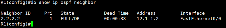
2.区域认证
- 明文认证
R1:
R1(config)#interface f0/0
//设置明文密码
R1(config-if)#ip ospf authentication-key cisco
R1(config-if)#exit
R1(config)#router ospf 100
//面向area 1开启认证
R1(config-router)#area 1 authentication
R2:
R2(config)#interface f0/0
R2(config-if)#ip ospf authentication-key cisco
R2(config-if)#exit
R2(config)#router os
R2(config)#router ospf 100
R2(config-router)#area 1 authentication
R2(config-router)#exit- 密文认证
R1:
R1(config)#interface f0/0
R1(config-if)#ip ospf message-digest-key 1 md5 cisco
R1(config-if)#exit
R1(config)#router ospf 100
R1(config-router)#area 1 authentication message-digest
R1(config-router)#exit
R2:
R2(config)#interface f0/0
R2(config-if)#ip ospf message-digest-key 1 md5 cisco
R2(config-if)#exit
R2(config)#router ospf 100
R2(config-router)#area 1 authentication message-digest
R2(config-router)#exit
总结:密文认证均需要在接口下设置加密方式与密码。
OSPF默认路由
1.若想下发默认路由,需证明自己是GW,且存在一条指向公网的默认路由。使用OSPF下发默认路由,下发的 是O E2的路由条目。
R1
R1(config)#ip route 0.0.0.0 0.0.0.0 12.1.1.2
R2
R2(config)#router ospf 100
//下发默认路由
R2(config-router)#default-information originate
R2(config-router)#exit
2.另一种情况:没有指向公网的路由,但是需要下发默认路由。
R2
//强制下发默认路由
R2(config-router)#default-information originate always
//选择版本,O E1或O E2
R2(config-router)#default-information originate always metric-type ?
  <1-2>  OSPF Link State type
OSPF虚链路
定义:虚连接是设置在两个路由器之间,这两个路由器都有一个端口与同一个非主干区域相连。虚连接被认为是属于主干区域的,在OSPF路由协议看来,虚连接两端的两个路由器被一个点对点的链路连接在一起。在OSPF路由协议中,通过虚连接的路由信息是作为域内路由来看待的。
使用场景:当OSPF网络出现常规区域之间彼此互联的情况,比如面临一些企业的合并或收购,需要临时的信息同步,这时就可以将常规区域间打通一个隧道进行连接,让常规区域的路由信息可以传递到骨干区域进行通信。配置虚拟链接所经过的区域称为传输区域。
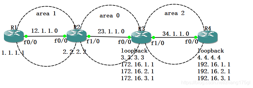
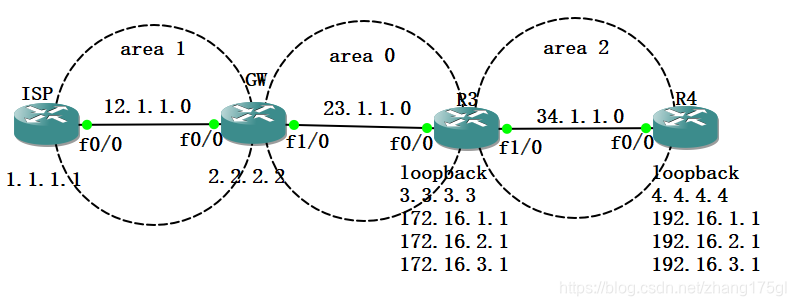
现在实验拓扑修改为上图所示。现在R4的环回口4.4.4.4想和R1产生通信。
以上图为例,4.4.4.4不属于OSPF网络,要想与area 0通信,中间间隔的area 1和area 2需要挨个做虚链路配置由于虚链路是双向的,所以报文发送过来的路程需要做配置,报文回复回去的路程也需要做配置。
R2
R2(config)#router ospf 100
//R2本身在area 0内,故只需要对返回的路程做配置
R2(config-router)#area 1 virtual-link 3.3.3.3
R3
R3(config)#router ospf 100
//R3不在area 0内,故报文来时的通道需要做一次配置
R3(config-router)#area 1 virtual-link 2.2.2.2
//报文返回时做一次配置
R3(config-router)#area 2 virtual-link 4.4.4.4
R4
R4(config)#router ospf 100
//报文发送往area 0的通道进行配置
R4(config-router)#area 2 virtual-link 3.3.3.3
现在在R1上查看OSPF路由表:
R1(config)#do show ip route ospf
     34.0.0.0/24 is subnetted, 1 subnets
O IA    34.1.1.0 [110/3] via 12.1.1.2, 00:04:12, FastEthernet0/0
     2.0.0.0/32 is subnetted, 1 subnets
O       2.2.2.2 [110/2] via 12.1.1.2, 00:04:12, FastEthernet0/0
     3.0.0.0/32 is subnetted, 1 subnets
O IA    3.3.3.3 [110/3] via 12.1.1.2, 00:04:12, FastEthernet0/0
     4.0.0.0/32 is subnetted, 1 subnets
O IA    4.4.4.4 [110/4] via 12.1.1.2, 00:04:12, FastEthernet0/0
     23.0.0.0/24 is subnetted, 1 subnets
O IA    23.1.1.0 [110/2] via 12.1.1.2, 00:04:12, FastEthernet0/0
     172.16.0.0/32 is subnetted, 3 subnets
O       172.16.1.1 [110/3] via 12.1.1.2, 00:04:12, FastEthernet0/0
O       172.16.3.1 [110/3] via 12.1.1.2, 00:04:12, FastEthernet0/0
O       172.16.2.1 [110/3] via 12.1.1.2, 00:04:12, FastEthernet0/0
O E2 192.16.0.0/22 [110/20] via 12.1.1.2, 00:04:12, FastEthernet0/0
可验证:虚链路已打通,外部信息可以与area 0骨干区域进行通信。
虚链路的认证
同接口认证和区域认证一样,虚链路也存在认证,这一切都是为了信息的安全而着想的。
- 明文认证
R2
R2(config)#router ospf 100
//通往目标地址的虚链路设置密码
R2(config-router)#area 1 virtual-link 3.3.3.3 authentication-key cisco
//启用密码认证
R2(config-router)#area 1 virtual-link 3.3.3.3 authentication
R3
R3(config)#router ospf 100
R3(config-router)#area 1 virtual-link 2.2.2.2 authentication-key cisco
R3(config-router)#area 1 virtual-link 2.2.2.2 authentication
因为处于同一个区域,故area 2内R4不需要做认证,area 0内的R1不需要做认证。此时R1已经可以收到来自area 2的报文。
- 密文认证
R3(config)#router ospf 100
//启用密文认证
R3(config-router)#area 1 virtual-link 2.2.2.2 authentication message-digest
//设置密文认证的密码
R3(config-router)#area 1 virtual-link 2.2.2.2 message-digest-key 1 md5 cisco
末节区域
在OSPF网络中,并不是每个路由器都需要自治系统外的网络信息,为了减少LSA泛洪量和路由表条目,就创建了末节区域(stub),位于Stub边界的ABR将宣告一条默认路由到所有的Stub区域内的内部路由器,不接受自治系统外部信息,同时也拒绝4类LSA,Stub区域不能包含ASBR(除非ABR也是ASBR)
在末节区域的基础上,如果既不接受自治系统外部路由也不接受自治系统内其他区域的汇总路由,则称该末节区域为完全末节区域。
骨干区域不能配置成Stub区域或Totally Stub区域。
如果要将一个区域配置成Stub区域,则该区域中的所有路由器必须都要配置stub命令。
如果要将一个区域配置成Totally Stub区域,该区域中的所有路由器必须配置stub命令,该区域的ABR路由器需要配置stub no-summary命令。
stub区域优化掉了4类和5类的LSA,并且ABR在区域内产生了一条3类的默认路由。
完全末节区域优化掉了3类的LSA并且ABR在该区域内产生了一条3类的O*IA默认路由。
R1
R1(config)#interface loopback 0
R1(config-if)#ip address 1.1.1.1 255.255.255.0
R1(config-if)#no shutdown
R1(config-if)#exit
R1(config)#interface f0/0
R1(config-if)#ip address 12.1.1.1 255.255.255.0
R1(config-if)#no shutdown
R1(config-if)#exit
R1(config)#router ospf 100
R1(config-router)#router-id 1.1.1.1
R1(config-router)#network 1.1.1.0 0.0.0.255 area 1
R1(config-router)#network 12.1.1.0 0.0.0.255 area 1
R1(config-router)#exit
R2
R2(config)#interface loopback 0
R2(config-if)#ip address 2.2.2.2 255.255.255.0
R2(config-if)#no shutdown
R2(config-if)#exit
R2(config)#interface f0/0
R2(config-if)#ip address 12.1.1.2 255.255.255.0
R2(config-if)#no shutdown
R2(config-if)#exit
R2(config)#interface f1/0
R2(config-if)#ip address 23.1.1.1 255.255.255.0
R2(config-if)#no shutdown
R2(config-if)#exit
R2(config)#router ospf 100
R2(config-router)#router-id 2.2.2.2
R2(config-router)#network 2.2.2.0 0.0.0.255 area 1
R2(config-router)#network 12.1.1.0 0.0.0.255 area 1
R2(config-router)#network 23.1.1.0 0.0.0.255 area 0
R2(config-router)#exit
R3
R3(config)#interface loopback 0
R3(config-if)#ip address 3.3.3.3 255.255.255.0
R3(config-if)#no shutdown
R3(config-if)#exit
R3(config)#interface f0/0
R3(config-if)#ip address 23.1.1.2 255.255.255.0
R3(config-if)#no shutdown
R3(config-if)#exit
R3(config)#interface f1/0
R3(config-if)#ip address 34.1.1.1 255.255.255.0
R3(config-if)#no shutdown
R3(config-if)#exit
R3(config)#interface f0/0
R3(config-if)#ip address 23.1.1.2 255.255.255.0
R3(config-if)#no shutdown
R3(config-if)#exit
R3(config)#router ospf 100
R3(config-router)#router-id 3.3.3.3
R3(config-router)#network 3.3.3.0 0.0.0.255 area 0
R3(config-router)#network 23.1.1.0 0.0.0.255 area 0
R3(config-router)#exit
R3(config)#router eigrp 100
R3(config-router)#no auto-summary
R3(config-router)#network 34.1.1.0 0.0.0.255
//将eigrp的路由条目重分发进ospf中
R3(config-router)#redistribute eigrp 100 subnets
R3(config-router)#exit
R4
R4(config)#interface loopback 0
R4(config-if)#ip address 4.4.4.4 255.255.255.0
R4(config-if)#no shutdown
R4(config-if)#exit
R4(config)#interface f0/0
R4(config-if)#ip address 34.1.1.2 255.255.255.0
R4(config-if)#no shutdown
R4(config-if)#exit
R4(config)#router eigrp 100
R4(config-router)#no auto-summary
R4(config-router)#network 34.1.1.0 0.0.0.255
R4(config-router)#network 4.4.4.0 0.0.0.255
- 末节区域的配置
R1(config)#router ospf 100
R1(config-router)#area 1 stub
R2(config)#router ospf 100
R2(config-router)#area 1 stub 此时在R1上查看路由表,可以发现4类的5类的LSA,即O E2的条目被优化掉了。
R1(config-router)#do show ip route
Codes: C - connected, S - static, R - RIP, M - mobile, B - BGP
D - EIGRP, EX - EIGRP external, O - OSPF, IA - OSPF inter area
N1 - OSPF NSSA external type 1, N2 - OSPF NSSA external type 2
E1 - OSPF external type 1, E2 - OSPF external type 2
i - IS-IS, su - IS-IS summary, L1 - IS-IS level-1, L2 - IS-IS level-2
ia - IS-IS inter area, * - candidate default, U - per-user static route
o - ODR, P - periodic downloaded static route
Gateway of last resort is 12.1.1.2 to network 0.0.0.0
1.0.0.0/24 is subnetted, 1 subnets
C 1.1.1.0 is directly connected, Loopback0
2.0.0.0/32 is subnetted, 1 subnets
O 2.2.2.2 [110/2] via 12.1.1.2, 00:26:19, FastEthernet0/0
3.0.0.0/32 is subnetted, 1 subnets
O IA 3.3.3.3 [110/3] via 12.1.1.2, 00:26:19, FastEthernet0/0
23.0.0.0/24 is subnetted, 1 subnets
O IA 23.1.1.0 [110/2] via 12.1.1.2, 00:26:19, FastEthernet0/0
12.0.0.0/24 is subnetted, 1 subnets
C 12.1.1.0 is directly connected, FastEthernet0/0
O*IA 0.0.0.0/0 [110/2] via 12.1.1.2, 00:26:20, FastEthernet0/0- 完全末节区域的配置
R1(config)#router ospf 100
R1(config-router)#area 1 stub //在ABR上进行配置
R2(config)#router ospf 100
R2(config-router)#area 1 stub no-summary 查看路由表可验证前文所述。
R1(config-router)#do show ip route
Codes: C - connected, S - static, R - RIP, M - mobile, B - BGP
       D - EIGRP, EX - EIGRP external, O - OSPF, IA - OSPF inter area
       N1 - OSPF NSSA external type 1, N2 - OSPF NSSA external type 2
       E1 - OSPF external type 1, E2 - OSPF external type 2
       i - IS-IS, su - IS-IS summary, L1 - IS-IS level-1, L2 - IS-IS level-2
       ia - IS-IS inter area, * - candidate default, U - per-user static route
       o - ODR, P - periodic downloaded static route

Gateway of last resort is 12.1.1.2 to network 0.0.0.0

     1.0.0.0/24 is subnetted, 1 subnets
C       1.1.1.0 is directly connected, Loopback0
     2.0.0.0/32 is subnetted, 1 subnets
O       2.2.2.2 [110/2] via 12.1.1.2, 00:38:06, FastEthernet0/0
     12.0.0.0/24 is subnetted, 1 subnets
C       12.1.1.0 is directly connected, FastEthernet0/0
O*IA 0.0.0.0/0 [110/2] via 12.1.1.2, 00:00:38, FastEthernet0/0
OSPF前缀抑制
OSPF使能网段时会将接口上匹配该网段的所有网段路由与主机路由都通过LSA发布,但有些时候主机路由或网段路由是不希望被发布的。通过前缀抑制配置,可以减少LSA中携带不需要的前缀,即不发布某些网段路由和主机路由,从而提高网络安全性,加快路由收敛。
当使能前缀抑制时,具体情况如下:
· P2P或P2MP类型网络:Type-1 LSA中不发布接口的主地址,即Type-1 LSA中链路类型为3的Stub链路被抑制,不生成接口路由,但其他路由信息可以正常计算,不会影响流量转发。
· 广播类型或者NBMA网络:DR发布的Type-2 LSA的掩码字段会填成32位,即不生成网段路由,但其他路由信息可以正常计算,不会影响流量转发。另外,如果没有邻居,发布的Type-1 LSA中也不发布接口的主地址,即Type-1 LSA中链路类型为3的Stub链路被抑制。
如果需要抑制前缀发布,建议整个OSPF网络都配置本命令。
进程下配置前缀抑制:
R1(config)#router ospf 100
R1(config-router)#prefix-suppression
R2(config)#router ospf 100
R2(config-router)#prefix-suppressionR3(config)#router ospf 100
R3(config-router)#prefix-suppression特点:缺省情况下,不抑制OSPF进程进行前缀发布。
不能抑制从地址、LoopBack接口以及处于抑制状态的接口对应的前缀。
端口下配置前缀抑制:
以R1为例,整个OSPF网络内的所有设备均需进行配置
R1(config)#interface f0/0
R1(config-if)#ip ospf prefix-suppression disable
NSSA
功能简述:Stub区域不能引入外部路由,为了在允许将自治系统外部路由通告到OSPF路由域内部的同时,保持其余部分的Stub区域的特征,网络管理员可以将区域配置为NSSA区域。NSSA区域也是位于AS边缘的非骨干区域。
配置nssa命令时指定no-summary参数可以将该区域配置为Totally NSSA区域,该区域的ABR不会将区域间的路由信息传递到本区域。
注意事项:骨干区域不能配置成NSSA区域或Totally NSSA区域。
如果要将一个区域配置成NSSA区域,则该区域中的所有路由器必须都要配置nssa命令。
如果要将一个区域配置成Totally NSSA区域,该区域中的所有路由器必须配置nssa命令,该区域的ABR路由器需要配置nssa no-summary命令。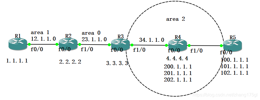
NASS区域
R3(config)#router ospf 100
R3(config-router)#area 2 nssa
R4(config)#router ospf 100
R4(config-router)#area 2 nssa R5(config)#router ospf 100
R5(config-router)#area 2 nssa
//下发默认路由
R3(config-router)#area 2 nssa default-information-originate R3上查看路由表如下图所示:
可见,5类的LSA被优化为7类O N路由条目。
完全NSSA区域
R3
R3(config)#router ospf 100
R3(config-router)#area 2 nssa no-summary R4
R4(config)#router ospf 100
R4(config-router)#area 2 nssa 此时在R4查看路由表: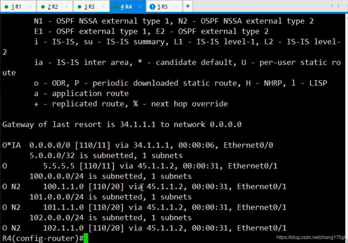
可发现Totally NSSA区域优化掉了3类的路由条目和从ABR上传来的4.5类路由条目,产生了一条3类O*IA的默认路由指向ABR,并把有ASBR传来的5类路由O E转换为7类的LSA。从而减小了路由表,提高了设备处理路由条目的性能。