使用GPIO模拟IIC接口时编写设备驱动的基本流程
开局三条狗,代码全靠粘
我也不熟这块,但是也就算是做出来了。。。。。。
用示波器观测 DY-TIVA-PB 板上的 TMP75 的 I2C 信号
一.IIC简介
I2C总线是一种应用非常广泛的双向二线制同步串行通信总线,两根线,分别为SCL和SDA。其中SCL是时钟线,SDA传输数据。
IIC有几种模式:
- 主机发送模式
- 主机接收模式
- 从机发送模式
- 从机接收模式
我们要知道II2在传输时的数据格式(数据帧)。每次传输都由一个起始位开始,然后以 9 位为一个周期传输地址或数据,最后以停止位终止。这 9 位是由 8 位的地址位(加指示位 R/S)或数据位以及 1 位应答位 ACK 组成的。直到停止。
如果是主机向从机写数据,也就是主机发送模式,那么就是如图所示的格式:
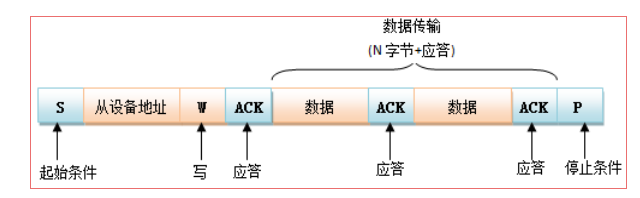
如果是读取数据的话,则要把写改为读。
具体的配置过程就不多讲了,这个有点复杂 (不熟),简要的说下重点
- 起始状态和停止状态时间间隔最小600ns,也就是说代码里要有一定的延时
void IIC_SendOneByte(uint32_t ui32Base, unsigned char TxValue){

	unsigned char i2cWriteBuffer = TxValue;
	uint16_t i2c_read_delay = TMP_READ_DELAY;

	I2CMasterDataPut(ui32Base, i2cWriteBuffer);
	I2CMasterControl(ui32Base, I2C_MASTER_CMD_BURST_SEND_CONT);

	while (i2c_read_delay--);
}
- 要设置主机和从机的地址
I2CMasterSlaveAddrSet(ui32Base, ui8SlaveAddr, false);//1001000
- 初始化并使能主机模式,使用系统时钟为 I2C0 模块提供时钟频率,主机模块传输速//率为 100Kbps
I2CMasterInitExpClk(I2C1_BASE, SysCtlClockGet(), true);
- 检查是否收到应答,否则有可能掉线了
bool IIC_RecvACK_Error(void){

	uint32_t i2cErrorState = I2CMasterErr(I2C1_BASE);
	if(i2cErrorState & I2C_MASTER_ERR_ADDR_ACK)
		return 0;	// 没有响应
	else
		return 1;
}
- 默认是10kΩ的上拉电阻,但这会导致上升时间慢,将两个上拉电阻改为1kΩ电阻后,上升时间有明显改善
二. 示例代码
这里TMP75传感器的地址是1001000,主机不断外发’A'~'Z'
#include <stdint.h>
#include <stdbool.h>
#include <stdio.h>
#include <stdarg.h>
#include <string.h>

#include "inc/hw_ints.h"
#include "inc/hw_memmap.h"
#include "inc/hw_types.h"
#include "inc/hw_gpio.h"
#include "inc/hw_i2c.h"
#include "inc/hw_sysctl.h"

#include "driverlib/sysctl.h"
#include "driverlib/systick.h"
#include "driverlib/gpio.h"
#include "driverlib/pin_map.h"
#include "driverlib/i2c.h"
#include "driverlib/fpu.h"
#include "utils/uartstdio.h"

#define TMP_PIN_I2C_PORT            I2C1_BASE
#define TMP_READ_DELAY              600         // fix for I2CMasterBusBusy
#define TMP_I2C_ADDR                0x48        // slave address (1001000)
#define TMP_TEMP_REG                0x0
#define TMP_CONFIG_REG              0x1
#define TMP_LOW_REG                 0x2
#define TMP_HIGH_REG                0x3
#define TMP_12                      0x60        // 01100000

#define ACK 1

void TMP75Initialize(uint32_t ui32Base, uint8_t ui8SlaveAddr);
void IIC_Start(uint32_t ui32Base);
void IIC_Stop(uint32_t ui32Base);
void IIC_SendACK(uint32_t ui32Base);
void IIC_SendOneByte(uint32_t ui32Base, unsigned char TxValue);
unsigned char IIC_RecvOneByte(uint32_t ui32Base);


void TMP75Initialize(uint32_t ui32Base, uint8_t ui8SlaveAddr)
{

	SysCtlPeripheralEnable(SYSCTL_PERIPH_I2C1);
	SysCtlPeripheralEnable(SYSCTL_PERIPH_GPIOA);

	GPIOPinTypeI2CSCL(GPIO_PORTA_BASE, GPIO_PIN_6);
	GPIOPinTypeI2C(GPIO_PORTA_BASE, GPIO_PIN_7);

	GPIOPinConfigure(GPIO_PA6_I2C1SCL);
	GPIOPinConfigure(GPIO_PA7_I2C1SDA);

	I2CMasterSlaveAddrSet(ui32Base, ui8SlaveAddr, false);//1001000
	I2CMasterInitExpClk(I2C1_BASE, SysCtlClockGet(), true);

}

void IIC_Start(uint32_t ui32Base){

	I2CMasterControl(ui32Base, I2C_MASTER_CMD_BURST_SEND_START);
}
void IIC_Stop(uint32_t ui32Base){

	I2CMasterControl(ui32Base, I2C_MASTER_CMD_BURST_SEND_FINISH);
}
void IIC_SendACK(uint32_t ui32Base){

	IIC_SendOneByte(ui32Base, ACK);
}
bool IIC_RecvACK_Error(void){

	uint32_t i2cErrorState = I2CMasterErr(I2C1_BASE);
	if(i2cErrorState & I2C_MASTER_ERR_ADDR_ACK)
		return 0;	// 没有响应
	else
		return 1;
}
void IIC_SendOneByte(uint32_t ui32Base, unsigned char TxValue){

	unsigned char i2cWriteBuffer = TxValue;
	uint16_t i2c_read_delay = TMP_READ_DELAY;

	I2CMasterDataPut(ui32Base, i2cWriteBuffer);
	I2CMasterControl(ui32Base, I2C_MASTER_CMD_BURST_SEND_CONT);

	while (i2c_read_delay--);
}
unsigned char IIC_RecvOneByte(uint32_t ui32Base){

	uint32_t i2cReadBuffer[2];
	uint16_t temp_value;
	uint16_t i2c_read_delay = TMP_READ_DELAY;

	// 从tmp75读取:
	// frame 3:
	I2CMasterSlaveAddrSet(ui32Base, TMP_I2C_ADDR, true);

	I2CMasterControl(ui32Base, I2C_MASTER_CMD_BURST_RECEIVE_START);

	// frame 4:
	i2cReadBuffer[0] = I2CMasterDataGet(I2C1_BASE);


	while (i2c_read_delay--);

	I2CMasterControl(ui32Base, I2C_MASTER_CMD_BURST_RECEIVE_CONT);

	    // frame 5:
	i2cReadBuffer[1] = I2CMasterDataGet(ui32Base);

	I2CMasterControl(ui32Base, I2C_MASTER_CMD_BURST_RECEIVE_FINISH);

	temp_value = i2cReadBuffer[0] | (i2cReadBuffer[1] << 8);

	return temp_value;

}

void main(){
	SysCtlClockSet(SYSCTL_SYSDIV_1|SYSCTL_USE_OSC|SYSCTL_XTAL_16MHZ | SYSCTL_OSC_MAIN);
	unsigned char data = 'A';
	while(1){

		TMP75Initialize(I2C1_BASE, TMP_I2C_ADDR);
		IIC_SendOneByte(I2C1_BASE, data++);
		if(data == 'Z')
			data = 'A';
		IIC_Start(I2C1_BASE);

		if(IIC_RecvACK_Error() == 0)
			continue;
		IIC_Stop(I2C1_BASE);
	}
}
接示波器

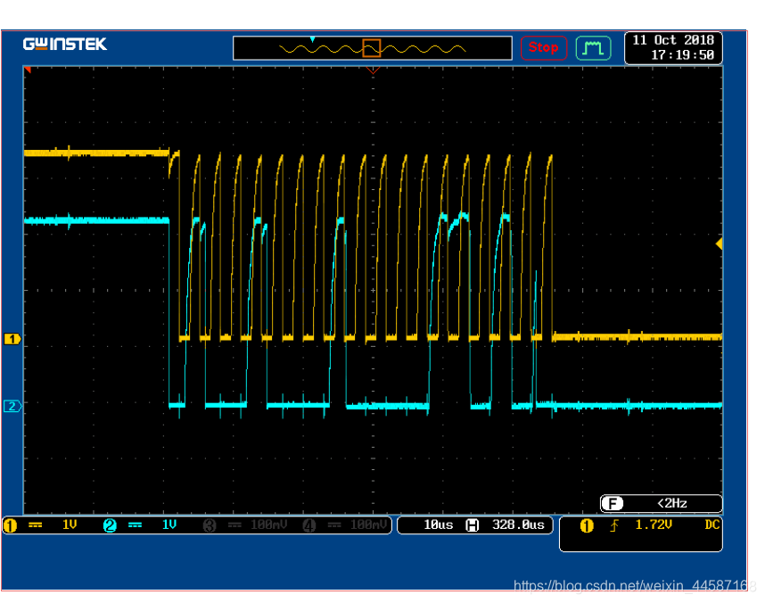
波形展开图

这里我们看到,传输的帧的格式为

按照前面的分析,前面是地址,中间有两位是读和应答位,再往后是数据传送区域,再是一个应答位,然后暂停
顺便补一句。。。。。图是盗的。。。。。。我不在实验室,当时做实验的时候波形跟这个差不多。这里版权归杨老师,图片上传送的数据并不是‘A’到‘Z’,但是也仅有数据的不同
而你当然可以把采集到的温度数据发送出去
还是保持链接的文件结构不变
提取码:gxpd
#include <stdint.h>
#include <stdbool.h>
#include <stdio.h>
#include <stdarg.h>
#include <string.h>
#include "inc/hw_ints.h"
#include "inc/hw_memmap.h"
#include "inc/hw_types.h"
#include "inc/hw_gpio.h"
#include "inc/hw_i2c.h"
#include "inc/hw_sysctl.h"
#include "driverlib/sysctl.h"
#include "driverlib/systick.h"
#include "driverlib/gpio.h"
#include "driverlib/pin_map.h"
#include "driverlib/i2c.h"
#include "driverlib/fpu.h"
#include "utils/uartstdio.h"
#include "TMP75.h"
#ifdef DEBUG
void
__error__(char *pcFilename, uint32_t ui32Line)
{
}
#endif
void ConfigureUART(void)
{
    SysCtlPeripheralEnable(SYSCTL_PERIPH_GPIOA);
    SysCtlPeripheralEnable(SYSCTL_PERIPH_UART0);
    GPIOPinConfigure(GPIO_PA0_U0RX);
    GPIOPinConfigure(GPIO_PA1_U0TX);
    GPIOPinTypeUART(GPIO_PORTA_BASE, GPIO_PIN_0 | GPIO_PIN_1);
    UARTStdioConfig(0, 115200, SysCtlClockGet());

}
void main(void)

{

    volatile float Temp;
    volatile unsigned char decimal;
    int Tempvalue;
    FPULazyStackingEnable();
    FPUEnable();
    SysCtlClockSet(SYSCTL_SYSDIV_1 | SYSCTL_USE_OSC | SYSCTL_OSC_MAIN |
                   SYSCTL_XTAL_16MHZ);
    ConfigureUART();
    UARTprintf("TMP75 Example\n");
    TMP75Init();
    while(1)

     {
        Temp=temp_read();
        Tempvalue = (int)Temp;

        decimal = (int)((Temp * 100)) % 100;
        UARTprintf("Temp = %d",Tempvalue);
        UARTprintf(".");
	       if(decimal < 10){
            UARTprintf("%d", 0);
            UARTprintf("%d", decimal);
        }
        else{
            UARTprintf("%d", decimal);
        }

        UARTprintf("\n");
        SysCtlDelay(SysCtlClockGet() /10);
     }
}

再看一下示波器的数据
这里看到数据位是0b00011010,换算一下也就是十进制的26,跟我串口里打印的数据的整数位比对一下,如果不吹气的话还是差不多的~
