导图

block_nonblock
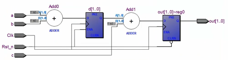
阻塞赋值
电路生成结果 与代码编写顺序是密切相关的
module block_nonblock(Clk,Rst_n,a,b,c,out);

	input clk;
	input Rst_n;
	input a,b,c;

    //out = a + b + c abc都是一位 out需要至少两位才能装的下
    //d = a + b
    //out = d + c
	output reg [1:0]out;
    reg [1:0] d;

	always@(posedge Clk or negedge Rst_n)
		if(!Rst_n)
			out = 2'b0;
		else  begin
			d = a + b;    //%%%%%%%%%%%
			out = d + c;  //%%%%%%%%%%%

	end
endmodule

把always中赋值的语句位置做调换 观察电路变化
module block_nonblock(Clk,Rst_n,a,b,c,out);

	input clk;
	input Rst_n;
	input a,b,c;

	output reg [1:0]out;
    reg [1:0] d;

	always@(posedge Clk or negedge Rst_n)
		if(!Rst_n)
			out = 2'b0;
		else  begin
			out = d + c; //%%%%%%%%%%%
			d = a + b;   //%%%%%%%%%%%

	end
endmodule

非阻塞赋值
module block_nonblock(Clk,Rst_n,a,b,c,out);

	input clk;
	input Rst_n;
	input a,b,c;

	output reg [1:0]out;
    reg [1:0] d;

	always@(posedge Clk or negedge Rst_n)
		if(!Rst_n)
			out = 2'b0;
		else  begin
			d <= a + b;  //%%%%%%%%%%%
			out <= d + c;  //%%%%%%%%%%%

	end
endmodule

把always中赋值的语句位置做调换 观察电路变化
module block_nonblock(Clk,Rst_n,a,b,c,out);

	input clk;
	input Rst_n;
	input a,b,c;

	output reg [1:0]out;
    reg [1:0] d;

	always@(posedge Clk or negedge Rst_n)
		if(!Rst_n)
			out = 2'b0;
		else  begin
			out <= d + c;  //%%%%%%%%%%%
			d <= a + b;    //%%%%%%%%%%%

	end
endmodule
可以看到是一模一样的
testbench仿真观察哪个是对的
`timescale 1ns/1ns
`define shizhong = 20
module block_nonblock_tb;

    reg clk1;
    reg ret_n1;
    reg a1,b1,c1;

	wire [1:0]out1;


	block_nonblock u1(
					.Clk(ckl1),
					.Rst_n(ret_n1),
					.a(a1),
					.b(b1),
					.c(c1),
					.out(out1)
					);

initial clk1 = 1;
always#(`shizhong/2) clk1 = ~clk1;
initial begin
		rst_n1 = 1'b0;
		a1 = 0;
		b1 = 0;
		c1 = 0;
		#(`shizhong*200 + 1); //+1 是为了 赋值时不与时钟上升沿严格对齐 好看一些

	    rst_n1 = 1'b1;
	    #(`shizhong*200 );

		a1 = 0; b1 = 0; c1 = 0;
		#(`shizhong*200 );
		a1 = 0; b1 = 0; c1 = 1;
		#(`shizhong*200 );
		a1 = 0; b1 = 1; c1 = 0;
		#(`shizhong*200 );
		a1 = 0; b1 = 1; c1 = 1;
		#(`shizhong*200 );
		a1 = 1; b1 = 0; c1 = 0;
		#(`shizhong*200 );
		a1 = 1; b1 = 0; c1 = 1;
		#(`shizhong*200 );
		a1 = 1; b1 = 1; c1 = 0;
		#(`shizhong*200 );
		a1 = 1; b1 = 1; c1 = 1;
		#(`shizhong*200 );

     	#(`shizhong*200 );
        $stop;
	end
endmodule
非阻塞赋值状态下


直到下一次时钟上升沿来了 out 才真正的变为01
虽然这样解释 但我们并不是看的很清楚啊 这个out=00的暂态是怎么来的
技巧:把底层代码的赋值时间延长 方便我们观看波形
`timescale 1ns/1ns
`define tp 1  //~~~~
module block_nonblock(Clk,Rst_n,a,b,c,out);

	input clk;
	input Rst_n;
	input a,b,c;

	output reg [1:0]out;
    reg [1:0] d;

	always@(posedge Clk or negedge Rst_n)
		if(!Rst_n)
			out = #`tp  2'b0;//~~~
		else  begin
			out <= #`tp  d + c;  //%%%%%%%%%%%~~~
		   	d <= #`tp  a + b;    //%%%%%%%%%%%~~~

	end
endmodule
再次进行testbench仿真

可以明确的看到:abc由000——》001后 d没有马上变化 下一个时钟上升沿才变化 out也是 没有马上变化
等到下一个时钟上升沿才发生了变化
上面 我们为了方便分析 加了#tp电路延迟 这个延迟只有在仿真的时候才会体现出来 实际生成电路的时候是没有的
这也就说明`
	d <= a + b;
	out <= d + c;
这两个语句不存在先后关系,不是我的d先有结果了 out再等于d+c 而是 我在对out进行计算的时候 直接取的就是上一个时钟上沿时 d和c的值之和
最好使用:out <= a + b + c 先把abc组合 再通过寄存器给 out
