1 STM32F103C8T6串口介绍
STM32F103C8T6有三个串口,每个串口有5个引出脚。分别是TX、RX、RTS、CTS、CK。以USART1为例,具体见如下截图。
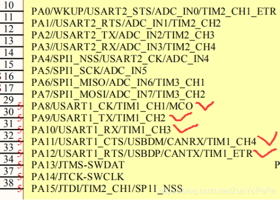
串口通讯中我们只用到TX和RX引脚就可以了。其他的引脚暂时不用去管它。其他几个引脚使用来做硬件流控制的。这里讲到的“流”,当然指的是数据流。数据在两个串口之间传输时,常常会出现丢失数据的现象,或者两台计算机的处理速度不同,如台式机与单片机之间的通讯,接收端数据缓冲区已满,则此时继续发送来的数据就会丢失。现在在网络上通过modem进行数据传输,这个问题就尤为突出。流控制能解决这个问题,当接收端数据处理不过来时,就发出“不再接收”的信号,发送端就停止发送,直到收到“可以继续发送”的信号再发送数据。因此流控制可以控制数据传输的进程,防止数据的丢失。
2 STM32F103C8T6串口配置步骤以及代码
配置步骤如下所示:
步骤一:使能串口时钟及GPIO端口时钟
步骤二:GPIO端口模式设置,设置串口对应的引脚为复用功能
步骤三:初始化串口参数,包含波特率、字长、奇偶校验等参数
步骤四:使能串口
步骤五:设置串口中断类型并使能
步骤六:设置串口中断优先级,使能串口中断通道
步骤七:编写串口中断服务函数
具体代码配置如下:
void USART_NVIC_Configuration(USART_TypeDef* USARTx)
{
NVIC_InitTypeDef NVIC_InitStructure;
unsigned short USART_IRQn=0;
#ifdef USE_USART1
if(USARTx==USART1) //串口1
{
USART_IRQn=USART1_IRQn;
}
#endif
#ifdef USE_USART2
if(USARTx==USART2) //串口2
{
USART_IRQn=USART2_IRQn;
}
#endif
#ifdef USE_USART3
if(USARTx==USART3) //串口3
{
USART_IRQn=USART3_IRQn;
}
#endif
 NVIC_InitStructure.NVIC_IRQChannel = USART_IRQn;
 NVIC_InitStructure.NVIC_IRQChannelPreemptionPriority=3 ;//抢占优先级3
 NVIC_InitStructure.NVIC_IRQChannelSubPriority = 3;		//子优先级3
 NVIC_InitStructure.NVIC_IRQChannelCmd = ENABLE;			//IRQ通道使能
 NVIC_Init(&NVIC_InitStructure);	//根据指定的参数初始化VIC寄存器
}
void USART_GPIO_Configuration(USART_TypeDef* USARTx)
{
GPIO_InitTypeDef GPIO_InitStructure;
#ifdef USE_USART1
if(USARTx==USART1)
{
RCC_APB2PeriphClockCmd(RCC_APB2Periph_USART1
|RCC_APB2Periph_GPIOA
|RCC_APB2Periph_AFIO, ENABLE);//使能USART1,GPIOA时钟以及复用功能时钟
GPIO_InitStructure.GPIO_Pin = GPIO_Pin_9; //PA.9
GPIO_InitStructure.GPIO_Speed = GPIO_Speed_50MHz;
GPIO_InitStructure.GPIO_Mode = GPIO_Mode_AF_PP; //复用推挽输出
GPIO_Init(GPIOA, &GPIO_InitStructure);
//USART1_RX PA.10
GPIO_InitStructure.GPIO_Pin = GPIO_Pin_10;
GPIO_InitStructure.GPIO_Mode = GPIO_Mode_IN_FLOATING;//浮空输入
GPIO_Init(GPIOA, &GPIO_InitStructure);
}
#endif
#ifdef USE_USART2
if(USARTx==USART2)
{
RCC_APB2PeriphClockCmd(RCC_APB2Periph_GPIOA|RCC_APB2Periph_AFIO, ENABLE);//使能USART2,GPIOA时钟以及复用功能时钟
GPIO_InitStructure.GPIO_Pin = GPIO_Pin_2; //PA.9
GPIO_InitStructure.GPIO_Speed = GPIO_Speed_50MHz;
GPIO_InitStructure.GPIO_Mode = GPIO_Mode_AF_PP; //复用推挽输出
GPIO_Init(GPIOA, &GPIO_InitStructure);
//USART2_RX PA.3
GPIO_InitStructure.GPIO_Pin = GPIO_Pin_3;
GPIO_InitStructure.GPIO_Mode = GPIO_Mode_IN_FLOATING;//浮空输入
GPIO_Init(GPIOA, &GPIO_InitStructure);
}
#endif
#ifdef USE_USART3
if(USARTx==USART3)
{
RCC_APB2PeriphClockCmd(RCC_APB2Periph_GPIOB|RCC_APB2Periph_AFIO, ENABLE);//使能USART3,GPIOB时钟以及复用功能时钟
GPIO_InitStructure.GPIO_Pin = GPIO_Pin_10; //PA.9
GPIO_InitStructure.GPIO_Speed = GPIO_Speed_50MHz;
GPIO_InitStructure.GPIO_Mode = GPIO_Mode_AF_PP; //复用推挽输出
GPIO_Init(GPIOB, &GPIO_InitStructure);
//USART3_RX PB.11
GPIO_InitStructure.GPIO_Pin = GPIO_Pin_11;
GPIO_InitStructure.GPIO_Mode = GPIO_Mode_IN_FLOATING;//浮空输入
GPIO_Init(GPIOB, &GPIO_InitStructure);
}
#endif
}
void USART_Configuration(USART_TypeDef* USARTx ,uint32_t BaudRate)
{
USART_InitTypeDef USART_InitStructure;
 USART_GPIO_Configuration(USARTx);   //串口GPIO配置
 USART_NVIC_Configuration(USARTx);    //USART _NVIC设置
#ifdef USE_USART2
if(USARTx==USART2)
{
RCC_APB1PeriphClockCmd(RCC_APB1Periph_USART2, ENABLE);
}
#endif
#ifdef USE_USART3
if(USARTx==USART3)
{
RCC_APB1PeriphClockCmd(RCC_APB1Periph_USART3, ENABLE);
}
#endif
 USART_InitStructure.USART_BaudRate = BaudRate; //波特率
USART_InitStructure.USART_WordLength = USART_WordLength_8b; //一个帧中传输或者接收到的数据位
 USART_InitStructure.USART_StopBits = USART_StopBits_1; //发送的停止位数
 USART_InitStructure.USART_Parity = USART_Parity_No;  //奇偶模式 USART_Parity_Even USART_Parity_Odd奇模式
 USART_InitStructure.USART_HardwareFlowControl = USART_HardwareFlowControl_None;//无硬件数据流控制
 USART_InitStructure.USART_Mode = USART_Mode_Rx | USART_Mode_Tx;	  //收发模式
 //串口初始化
 USART_Init(USARTx, &USART_InitStructure);

 //启动串口 空间中断	  接收空闲中断使能
 USART_ITConfig(USARTx, USART_IT_RXNE, ENABLE);

 //使能串口
 USART_Cmd(USARTx, ENABLE);
}
void USART1_IRQHandler(void) //串口1中断服务程序
{
unsigned int ReceiData;
if(USART_GetITStatus(USART1, USART_IT_RXNE) != RESET) //接收中断
{
ReceiData =USART_ReceiveData(USART1);//(USART1->DR); //读取接收到的数据
if( ReceiData0x10)
{
LED3=0;
}
if( ReceiData0x20)
{
LED3=1;
}
}
USART_ClearFlag(USART1,USART_FLAG_TC);
}
void USART2_IRQHandler(void) //串口2中断服务程序
{
unsigned int USART2ReceiData;
if(USART_GetITStatus(USART2, USART_IT_RXNE) != RESET) //接收中断
{
USART2ReceiData =USART_ReceiveData(USART2);//(USART1->DR); //读取接收到的数据
if( USART2ReceiData0x10)
{
LED3=0;
}
if( USART2ReceiData0x20)
{
LED3=1;
}
}
USART_ClearFlag(USART2,USART_FLAG_TC);
}
void USART3_IRQHandler(void) //串口3中断服务程序
{
unsigned int USART3ReceiData;
if(USART_GetITStatus(USART3, USART_IT_RXNE) != RESET) //接收中断
{
USART3ReceiData =USART_ReceiveData(USART3);//(USART1->DR); //读取接收到的数据
if( USART3ReceiData0x10)
{
LED3=0;
}
if( USART3ReceiData0x20)
{
LED3=1;
}
}
USART_ClearFlag(USART3,USART_FLAG_TC);
}

#include “oled.h”
#include “usart.h”
#include “stdio.h”
#include “stm32f10x_tim.h”
#define USE_USART1
#define USE_USART2
#define USE_USART3
int main(void)
{
NVIC_Configuration();
OLED_Init();
USART_Configuration(USART3 ,9600);
USART_Configuration(USART2 ,115200);
USART_Configuration(USART1 ,115200);
while(1);
}
