Intel GEN11 GPU
2 ARCHITECTURE HIGHLIGHTS
Coarse pixel shading (CPS)
The motivation of tile-based rendering is to reduce memory bandwidth by efficiently managing multiple render passes to data per tile on die.
In order to support tile based rendering, Gen11 adds a parallel geometry pipeline that acts as a tile binning engine. It is used ahead of the render pipeline for visibility binning prepass per tile. It loops over geometry per tile and consumes visibility stream for that tile.
PTBR accomplishes its goal to keep data per tile on die by utilizing the L3 cache which has been enhanced to support color and Z formats. This collapses all the memory reads and writes within the L3 cache thereby reducing the external bandwidth.
3 SYSTEM ON A CHIP (SOC) ARCHITECTURE
Intel’ processors are complex SoCs integrating multiple CPU cores, Intel® Gen11 processor graphics and additional fixed functions all on a single shared silicon die. The architecture implements multiple unique clock domains, which have been partitioned as a per-CPU core clock domain, a processor graphics clock domain, and a ring interconnect clock domain. The SoC architecture is designed to be extensible for a range of products and enable efficient wire routing between components within the SoC.
4 THE GEN11 PROCESSOR GRAPHICS ARCHITECTURE
Gen11 architecture is an evolution over Gen9 with enhancements throughout the architecture to improve performance per flop by removing bottlenecks and improving the efficiency of the pipeline.
Gen11 is a 64EU Architecture supporting 3D rendering, compute, programmable and fixed function media capabilities. Gen11 architecture is split into: Global Assets which contains some fixed function blocks that interface to the rest of the SoC, the Media FF, the 2D Blitter and the Slice. The Slice houses the 3D Fixed Function Geometry, 8 sub-slices containing the EUs, and a slice common that contains the rest of the fixed function blocks supporting the render pipeline and L3 cache. Figure2 reflects this categorization.
4.3.1 Geometry
Gen11 3D Geometry Fixed Function contains the typical render front-end that maps to the logical pipeline in DirectX™, Vulkan™, OpenGL™ or Metal™ APIs. Additionally, it includes a Position Only Shading pipeline, or POSh pipeline used to implement Tile-Based Rendering (PTBR). This Section describes the traditional geometry pipeline while section 5.2 describes the POSh pipeline used in tile based rendering.
Vertex fetch (VF), one of the initial stages in the geometry pipe is responsible for fetching vertex data from memory for use in subsequent vertices, reformatting it, and writing the results into an internal buffer. Typically, a vertex consists of more than one attribute, e.g. position, color, normal, texture coordinates, etc. Usage of more vertex attributes has grown with increases in workload complexity. To that end, Gen11 increases the VF input rate from 4 attributes/clock to 6 attributes/clock as well as improves the input data cache efficiency. Another important VF change in Gen11 is the increase in number of draw calls handled concurrently to enable streaming of back to back draw calls. Newer APIs like DX12™* and Vulkan™* have significantly reduced the overheads for draw calls, enabling workloads to improve visuals by increasing the number of draw calls per frame.
Gen11 has also made tessellation improvements. It provides up to a 2X increase in the Hull Shader thread dispatch rate as well as further increases the output topology efficiency, especially for patch primitives subject to low tessellation factors.
4.3.2.1 Execution Unit (EU) Architecture
The foundational building block of Gen11 architecture is the execution unit, commonly abbreviated as EU. The architecture of an EU is a combination of simultaneous multi-threading (SMT) and fine-grained interleaved multi-threading (IMT). These EUs are compute processors that drive multiple issue, single instruction, multiple data arithmetic logic units (SIMD ALUs) pipelined across multiple threads, for high-throughput floating-point and integer compute. The fine-grain threaded nature of the EUs ensures continuous streams of ready to execute instructions, while also enabling latency hiding of longer operations such as memory scatter/gather, sampler requests, or other system communication. Depending on the software workload, the hardware threads within an EU may all be executing the same compute kernel code, or each EU thread could be executing code from a completely different compute kernel.
4.3.2.2 SIMD ALUs
In each EU, the primary computation units are a pair of SIMD floating-point units (ALUs). Although called ALUs, they support both floating-point and integer computation. These units can execute up to four 32-bit floating-point (or integer) operations, or up to eight 16-bit floating-point operations. Effectively, each EU can execute 16 FP32 floating point operations per clock [2 ALUs x SIMD-4 x 2 Ops (Add + Mul)] and 32 FP16 floating point operations per clock [2 ALUs x SIMD-8 x 2 Ops (Add + Mul)].
Each EU is multi-threaded to enable latency hiding for long sampler or memory operations. Associated with each EU is 28KB register file (GRF) with 32bytes/register.
As depicted in Figure 4, one of the ALUs support 16-bit and 32-bit integer operations and the other ALUs provides extended math capability to support high-throughput transcendental math functions.
4.3.2.3 SIMD Code Generation for SPMD Programming Models
Compilers for single program multiple data (SPMD) programming models, such as OpenCL™*, Microsoft DirectX** Compute Shader, OpenGL** Compute, and C++AMP™*, generate SIMD code to map multiple kernel instances2 to be executed simultaneously within a given hardware thread. The exact number of kernel instances per-thread is a heuristic driven compiler choice. We refer to this compiler choice as the dominant SIMD-width of the kernel. In OpenCL™* and DirectX™* Compute Shader, SIMD-8, SIMD-16, and SIMD-32 are the most common SIMDwidth targets.
4.3.3 Shared Local Memory
The SLM is a 64KB highly banked data structure accessible from the 8 EUs in the Subslice. The change in architecture is depicted Figure 5. In Gen11 architecture, the SLM and memory access are split such that the one is through the dataport function while the other is accessed directly from the EUs.
The proximity to the EUs provides low latency and higher efficiency since SLM traffic does not interfere with L3/memory access through the dataport or sampler. The SLM is banked to byte granularity allowing high degree of access flexibility from the EUs. This change provides an increase in the overall effective rate of local and global atomics.
SPMD programming model constructs such as OpenCL’s™* local memory space or DirectX™* Compute Shader’s shared memory space are shared across a single work-group (threadgroup). For software kernel instances that use shared local memory, driver runtimes typically map all instances within a given OpenCL™* work-group (or a DirectX™* thread group) to EU threads within a single subslice. Thus all kernel instances within a work-group will share access to the same 64 Kbyte shared local memory partition. Because of this property, an application’s accesses to shared local memory should scale with the number of subslices.
4.3.4 Texture Sampler
The Texture Sampler is a read-only memory fetch unit that may be used for sampling of texture and image surface types 1D, 2D, 3D, cube, and buffers. The sampler includes a cache, a decompressor, and a filter block. The Texture Sampler supports dynamic decompression of many block compression texture formats such as DirectX™* BC1-BC7, and OpenGL™* ETC, ETC2, and EAC. Additionally, the texture sampler supports lossless compressed surfaces. The sampler is also compliant with the latest Compute and 3D API’s for capability and quality.
Improvements on Gen11 include:
Sampling rate for anisotropic filtering of 32bit surface formats is increased by 2X for all depths of anisotropy (2X anisotropic filtering is now the same rate as trilinear filtering).
Sampling rate on volumetric surfaces has been increased by 2X on point sampled 32bit formats as well as bilinear filtered 64bit formats (point-sample is now full-rate of 4ppc for most surface formats).
Sampling rate for trilinear filtering of 2D surfaces with 64bit surface formats is increased by 2X.
4.4 SLICE COMMON
4.4.1 Raster
The Raster block converts polygons to a block of pixels called subspans. Gen11 significantly increases the conversion rate by 16x for 1xAA and by 4X for 4xMSAA.
In addition to normal rasterization, Gen9 supports conservative rasterization which tests pixel for partial coverage and marks it as covered for rasterization. This implementation meets the requirements of tier3 hardware per D3D12 specification and enables advanced rendering algorithms for collision detection, occlusion culling, shadows or visibility detection. Gen11 improves conservative rasterization throughput by about 8x.
Besides supporting rendering primitives, Gen devices also support line rendering which are typically important in workstation applications.
4.4.2 Depth
The depth test function is used to perform the “Z Buffer” hidden surface removal. The depth test function can be used to discard pixels based on a comparison between the incoming pixee
l’s depth value and the current depth buffer value associated with the pixel
Depth tests are performed at two levels of granularity, coarse and fine. The coarse tests are performed by HiZ where testing is done on 8x4 pixel block granularity. In addition, the HiZ block supports Fast Clear which allows clearing depth without writing the depth buffer. The test performed at a finer granularity (per pixel, per sample) are done by the Z block.
In Gen11, the Z buffer min/max is back annotated into HiZ buffer reducing future nondeterministic or ambiguous tests. When HiZ buffer does not have visibility data till post shader, the resulting tests are nondeterministic in HiZ resulting in Z to per pixel testing. Back annotation allows updating the HiZ buffer with results from Z buffer as shown in figure 6. HiZ test range is narrowed, resulting in coarse testing instead of pixel level for normal rendering or per sample level when MSAA is enabled. Thus, the overall depth test throughput is increased while the corresponding Z memory BW is simultaneously decreased.
4.4.3 Pixel Dispatch
The Pixel Dispatch block accumulates subspans/pixel information and dispatches threads to the execution units. The pixel dispatcher, decides the SIMD width of the thread to be executed, choosing between SIMD8, SIMD16 and SIMD32. Pixel Dispatch chooses this to maximize execution efficiency and utilization of the register file. The block load balances across the shader units and ensures order in which pixels retire from the shader units.
In Gen11, pixel dispatch includes the function of “coarse pixel shader” which is described in detail in Sections 5.1. When CPS is enabled, the coarse pixels generated are packed whichh
reduces the number of pixel shading invocations. The reference or the mapping of a coarse pixel to pixel is maintained until the pixel shader is executed.
4.4.4 Pixel Backend/Blend
The Pixel Backend (PBE) is the last stage of the rendering pipeline which includes the cache to hold the color values. This pipeline stage also handles the color blend functions across several source and destination surface formats. Lossless color compression is handled here as well.
Gen11 exploits use of lower precision in render target formats to reduce power for blending operations
4.4.5 Level-3 Data Cache
In Gen11, the L3 data cache capacity has been increased to 3MB. Each application context has flexibility as to how much of the L3 memory structure is allocated in:
Application L3 data cache
System buffers for fixed-function pipelines.
For example, 3D rendering contexts often allocate more L3 as system buffers to support their fixed-function pipelines.
All sampler caches and instruction caches are backed by L3 cache. The interface between each Dataport and the L3 data cache enables both read and write of 64 bytes per cycle.
Z, HiZ, Stencil and color buffers may also be backed in L3 specifically when tiling is enabled.
In typical 3D/Compute workloads, partial access is common and occurs in batches and makes ineffective use of memory bandwidth. In Gen11, when accessing memory, L3 cache opportunistically combines partial access of a pair of 32B to a single 64B thereby improving efficiency.
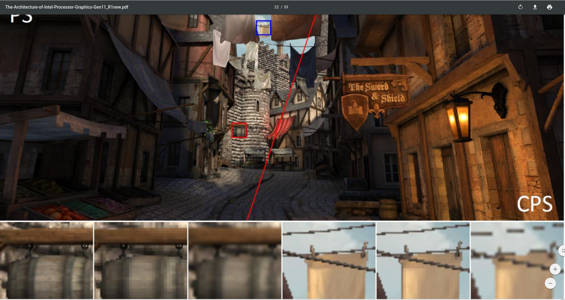
The canonical Citadel 1 CPS image rendered at 2560x1440 with a 1x1 pixel rate on the left and 2x2 CPS shading on the right. While CPS halves the number of shader invocations, there is almost no perceivable difference on a high pixel density display. An up-scaled image with no anti-aliasing applied is also shown for comparison rendered at 1280x720. Reprinted with permission from [Vaidyanathan et al. 2014].