文章目录
前言
本文所涉及的主题(见标题)是最重要的部分,没有之一,原因如下:
in order to have a nice looking, fast displaying, fast simulating and stable simulation model
创建可见的形状
- 首先我们只考虑模型的可见部分,而动态部分(如关节,传感器)后续再处理。
the dynamic aspect (its undelying even more simplified/optimized model), joints, sensors, etc. will be handled at a later stage
- 我们可以创建pure形状或regular形状(软件自带),前者为了动力学交互被优化过,且动力学选项默认enabled,至于primitive形状只是简单的网格,不一定包含足够的细节和几何上准确度
- 我们也可以从外部应用导入mesh模型,即CAD数据,导入数据时,CAD数据不要过于复杂,影响仿真速度
we have the option to create pure shapes, or regular shapes. Pure shape will be optimized for dynamic interaction, and also directly be dynamically enabled (i.e. fall, collide, but this can be disabled at a later stage). Primitive shapes will be simple meshes, which might not contain enough details or geometric accuracy for our application. Our other option in that case would be to import a mesh from an external application.
模型预处理
为了不让CAD数据过于复杂,进行以下处理:
- 移除小孔,螺丝,物体内部成分(我们只需要外壳)
try to remove all the holes, screws, the inside of objects, etc. from your original model data.
If you have the original model data represented as parametric surfaces/objects, then it is most of the time a simple matter of selecting the items and deleting them (e.g. in Solidworks).
- 限制精确度
The second important step is to export the original data with a limited precision
- 分步导入物体,先大物体(精确度设置为低),后小物体(精确度较高)
简化mesh
- 注意到导入的模型一般为单个mesh(a single mesh),要对其分割,但其初始方向(orientation)通常是错误的,但暂时先不改变,理由见下文:
best is to keep the orientation as it is, until the whole model was built, since, if at a later stage we want to import other items that are related to that same robot, they will automatically have the correct position/orientation relative to the original mesh.
简化方法
- 自动mesh划分(附英语原文):
- 允许通过共同的边缘,为那些没有连接在一起的部分产生一个新的形状,并不总是奏效但值得尝试,因为仅作用于选定的mesh elements总比作用于所有elements要好,具体实现方式:[Menu bar --> Edit --> Grouping/Merging --> Divide selected shapes]
- 有时会划分过度,我们这时需要来进行合并逻辑上属于一起(如同一连杆的一部分,有相同的视觉属性)的部分为单个形状(grouping)
allows to generate a new shape for all elements that are not linked together via a common edge. This does not always work for the selected mesh, but is always worth a try, since working on mesh elements gives us more control than if we had to work on all elements at the same time.
Sometimes, a mesh will be divided more than expected. In that case, simply merge elements that logically belong together (i.e. that will have the same visual attributes and that are part of the same link) back into one single shape ([Menu bar --> Edit -> Grouping/Merging --> Merge selected shapes]).
- 提取凸包:将mesh转换为凸包来简化
- 对mesh进行decimate(十中取一):减少mesh里包含的三角形(mesh由三角形构成)数量,理解为降采样
- 移除mesh内部成分:该功能基于视觉传感器,根据所选择的的设置可能取得更好或更差的结果,具体实现方式: [Menu bar --> Edit --> Extract inside of selected shape]
效果图

- 上图分别对应Convex hull, decimated mesh, and extracted inside
- 上述方法中自动mesh划分总是被推荐去尝试,其他取决于导入的mesh几何性质
应用
先对mesh进行decimate两次,然后extract the inside of the shape,OK,最终得到的是整个机器人模型的a single shape
划分为连杆
-
前面的步骤使我们获得了a single shape for the whole robot,下面还要分为不同的link(连杆)
-
自动mesh划分(前文已提及):inspect the shape and generate a new shape for all elements that are not linked together via a common edge
-
手动划分(绝大部分情况):进入 triangle edit mode,选择三角形,然后 Extract shape,提出后删除之前选中的三角形
含空洞模型的划分(拓展)
接着考虑到有时用凸包视觉效果会更好,如下图
孔洞影响简化模型的操作,所以手动编辑,提取逻辑上属于一个凸实体的部分,具体如下:
- 首先提取三个近似凸形成分(不同颜色标注了),此时忽略两个孔洞的三角形,最终得到三个形状(shapes)

- 其中两个形状进一步改善,即:去除那些空洞的三角形,然后为三个形状各自提取凸包,再合并(merging)

统一各部分属性
-
在shape properties中,我们可以选择是否显示形状边缘或者在边缘显示时指定要考虑的角度,一个示例就是shading angle,指明形状要显示哪个面。
-
下一步,我们要合并逻辑上属于一体(一个连杆的不同部分)的成分,使得它们视觉上呈现一样的效果,方法就是先搞掂一个形状,然后选中它,再Ctrl+选中其他要统一为一体的所有形状,apply to selection,就OK啦!
-
接着,在完成视觉属性的统一后,再合并相同部分,具体的: [Menu bar --> Edit --> Grouping/merging -> Group selected shapes]
-
当创建形状时,默认设置其参考坐标系位置为形状的几何中心,而姿态则是遵循使得形状的bounding box即包围盒越小越好,但我们可以重新设置形状的参考坐标系:[Menu bar --> Edit --> Reorient bounding box --> with reference frame of world]
创建关节
若我们只有D-H参数,则我们可以通过工具模型(模型浏览器窗口里)创建。
we can build our joints via the tool model located in Models/tools/Denavit-Hartenberg joint creator.ttm, in the model browser.
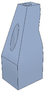
大部分情况下我们要自己从mesh中提取形状,可以从原始CAD数据模型提取,而不是简化后的数据模型
首先subdivide原始的mesh,如果不行的话,则手动进入三角形编辑模式,然后找revolute形状,作为要创建关节所在位置和姿态的参考,此时移除其他不需要的形状,便于操作,如下图为一机器人基座,其用于设置第一个关节的位姿
 Robot base: normal and triangle edit mode visualization
用tool button来调整视角,如fit-to-view按钮,加入vertex edit mode,选择所有属于上圆盘的顶点,然后进入triangle edit mode,如图

然后选择extract cylinder,然后基于选择的形状,产生一个cylinder形状,然后添加旋转关节并选中,接着Ctrl+选中上述提取出的cylinder形状,之后分别使得两者位置和姿态对应(分别使用位置和姿态调整按钮)。有时,我们还需要将关节环绕其自己的参考坐标系旋转90度或180度,来获得正确的状态或旋转方向,旋转操作可通过 rotation tab 进行。同样的方式,你可以让关节沿着其轴线移动,最终效果如下:

对模型所有的关节创建如上述所示进行,记住关节默认在layer 2,此时,我们完成了模型的大体定义和层次树,但还需要添加动力学性质。
添加动力学(❤)
所谓有动力学属性,即一个形状满足以下要求:
- dynamic or static:
- 具有动力学属性(也称为非静态)的形状能被外部力或力矩影响或fall,而没有动力学属性的形状要么原地不动,要么跟随父节点在场景中的移动
- respondable or non-respondable:
- 即该形状能对其他respondable形状引起碰撞反应。此时,若它们均是dynamic(enabled),则在运动中互相影响。而非respondable的状态在与其他形状碰撞时不计算碰撞反应。
综上所述,respondable形状应该尽可能简单,便于计算的稳定性和迅速性,物理引擎能对以下五种类型形状进行仿真:
Pure shapes: a pure shape will be stable and handled very efficiently by the physics engine. The draw-back is that pure shapes are limited in geometry: mostly cuboids, cylinders and spheres. If possible, use those for items that are in contact with other items for a longer time (e.g. the feet of a humanoid robot, the base of a serial manipulator, the fingers of a gripper, etc.). Pure shapes can be created with [Menu bar --> Add --> Primitive shape].
- 纯形状:仿真效率很高,很稳定,缺点在于局限于以下几何体:圆柱,球体和立方体,如果有可能的话,当需要长时间接触时,用这些形状构成的物体来来与其他物体接触,如人形机器人足部,串联机器人基座,抓手手指等
Pure compound shapes: a pure compound shape is a grouping of several pure shapes. It performs almost as well as pure shapes and shares similar properties. Pure compound shapes can be generated by grouping several pure shapes [Menu bar --> Edit --> Grouping/Merging --> Group selected shapes].
- 纯复合形状:纯形状组合而成,性能表现与纯形状差不多,可通过grouping几个纯形状获得
Convex shapes: a convex shape will be a little bit less stable and take a little bit more computation time when handled by the physics engine. It allows for a more general geometry (only requirement: it need to be convex) than pure shapes. If possible, use convex shapes for items that are sporadically in contact with other items (e.g. the various links of a robot). Convex shapes can be generated with [Menu bar --> Add --> Convex hull of selection] or with [Menu bar --> Edit --> Morph selection into convex shapes].
- 凸形状:相比于纯形状,稍微不稳定,计算成本稍微上升,但几何要求降低了,更一般了(唯一要求就是是凸形的),若是sporadic接触,用凸形状构成的物体来进行(如机器人的不同连杆)
Compound convex shapes, or convex decomposed shapes: a convex decomposed shape is a grouping of several convex shapes. It performs almost as well as convex shapes and shares similar properties. Convex decomposed shapes can be generated by grouping several convex shapes [Menu bar --> Edit --> Grouping/Merging --> Group selected shapes], with [Menu bar --> Add --> Convex decomposition of selection…], or with [Menu bar --> Edit --> Morph selection into its convex decomposition…].
- 复合凸形状,也称为分解后的凸形状:凸形状组合而成,性能表现同凸形状差不多,可通过grouping几个凸形状
Random shapes: a random shape is a shape that is not convex nor pure. It generally has poor performance (calculation speed and stability). Avoid using random shapes as much as possible.
- 随机形状是一种即非纯形状也非凸形状的形状,性能表现较差,尽量避免使用
综上所述,优先级如下:纯形状,纯复合形状,凸形状,凸复合形状和随机形状。
对于机器人,我们将基座作为纯圆柱形状,而其他连杆作为凸或凸复合形状
按道理说,我们也可以用动力学属性已经enabled的形状作为机器人的可见部分,但那样看起来不太好,所以我们为该手册第一部分创建的可见形状创建动力学属性enabled的对应部分,但设置为隐藏(不用现成的形状,自己创建形状【第一部分已完成】,然后创建对应的动力学模型,只供物理引擎使用),而可见的机器人部分只用于视觉效果以及最小距离模块,接近传感器的探测等
处理基座
对于机器人,我们将基座作为纯圆柱形状,而其他连杆作为凸或凸复合形状
依照上文所述,操作:选中机器人,若机器人是复合形状,则首先要ungroup,然后将individual shapes合并出所要操作的目标形状(如基座),进入三角形编辑模式,选中组成电源线的三角形形状,erase them,然后选取该形状的所有三角形,提取纯圆柱,最终得到纯圆柱所代表的基座

处理连杆
下面处理连杆(作为凸形状或凸复合形状):
选中连杆,然后从中产生凸形状Menu bar --> Add --> Convex hull of selection,若觉得丢失很多原形状的细节,你可以从composing elements来手动提取所有的凸包,然后合并,或者使用自动的方法Menu bar --> Add --> Convex decomposition of selection
you could manually extract several convex hulls from its composing elements, then group all the convex hulls with [Menu bar --> Edit --> Grouping/Merging --> Group selected shapes]. If that appears to be problematic or time consuming, then you can automatically extract a convex decomposed shape with [Menu bar --> Add --> Convex decomposition of selection…]:
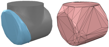
Original shape, and convex shape pendant
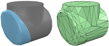
Original shape, and convex decomposed shape pendant
接着对于其余连杆,重复上述操作,完成后将每个动态模型attach到对应的visible部分
效果图

考虑到我们要让动态模型只为物理引擎所用,而不是其他calculation module,所以uncheck所有的object special properties
- 接着我们仍然需要将动态模型设置为dynamic和respondable,在shape dynamics properties中设置,首先enable基座的respondable属性,以及enable前四个local respondable mask标志位,disable后四个local respondable mask标志位(为了让连续的respondable连杆不相互碰撞),然后对于第一个连杆(与基座相连),仍然enable respondable属性,但这次*disable前四个local respondable mask标志位,enable后四个local respondable mask标志位,重复上述过程,使得掩码交替。理由如下:
once the model will be defined, consecutive dynamic shapes of the robot will not generate any collision response when interacting with each other. Try to always end up with a construction where the dynamic base of the robot, and the dynamic last link of the robot have only the first 4 Local respondable mask flags enabled, so that we can attach the robot to a mobile platform, or attach a gripper to the last dynamic link of the robot without dynamic collision interferences.
最后,我们需要将动态模型的dynamic属性也enable下,在shape dynamics properties中设置,然后设置mass和inertia Tensor properties,可手动或自动设置:点击 Compute mass & inertia properties for selected convex shapes。
同时,注意到基座的特殊性,当机器人单独使用时,我们希望其实非动态的(static),以避免机械臂运动时基座fall,但若将机械臂与小车绑定,我们又希望基座能dynamic(非静态),可通过enabling the Set to dynamic if gets parent item, then disabling the Body is dynamic item达到目的。
此时运动仿真时,除了基座(通过上述设置)其他的动态shape都会fall,当然,用于视觉效果的visual shapes也会跟着fall。
定义模型
拖拽方式获得如下层次结构(关节加入层次树)

将机器人模型基座重新命名,毕竟基座代表整个模型(作为超父节点),此时,选中层次树的超父节点,即基座(robot节点),enable基座的 Object is model base以及 enable Object/model can transfer or accept DNA,从而产生包围盒(包围机器人模型),但这个包围盒太大了,是因为其还包含了不可见部分(如 joint,传感器),所以要为所有关节enable the Don’t show as inside model selection item,同理,对于其他不可见部分同样处理,最终效果

- 接着为了不让机器人模型被意外修改,选中机器人模型中的所有可见object,然后enable Select base of model instead,达到选择机器人模型任一部分,却是选择机器人base的目的(一体化),此时若想确实选中特定部分,要在层次树中选择。
- 接着我们要把机器人模型放在正确的默认位姿上(put the robot into a correct default position/orientation),首先保存当前scene为参考系,接着选中模型并修正位姿(一种做法是使模型,即base,位于X=0,Y=0位置)
First, we save current scene as a reference (e.g. if at a later stage we need to import CAD data that have the same orientation at the curent robot). Then we select the model and modify its position/orientation appropriately. It is considered good practice to position the model (i.e. its base object) at X=0 and Y=0.

Robot model in default configuration
-
此时运行仿真,机器人立刻collapse,是由于没有设置关节控制参数,之前我们添加关节时只是让关节处于力/力矩模式,而没有enable motor or controller,现在我们想要用PID控制器控制每个关节,所以在joint dynamic properties,我们点击 Motor enabled 并调整 the maximum torque,接着我们点击Control loop enabled 并选择 Position control (PID),这回运行仿真,机器人能保持位置
-
仿真时,我们能通过 Dynamic content visualization & verification toolbar button(选择仿真引擎旁边的按钮)来验证场景的动态内容,选中则只显示物理引擎考虑的内容(即动态模型),这样做的好处在于便于debug,更快发现动态模型表现不如预期的原因,注意到仿真过程中,动力学enable的object名字右边有球状物:
dynamically enabled objects should display a ball-bounding icon on the right-hand side of their name

具有动力学形状的连接
-
接着我们要将一gripper放在机器人上或者将机器人放在移动平台上,一般两个动力学enable的形状要想 rigidly attached to each other(互相连接)有两种方法:
-
通过组合方式:选择两个形状,然后 [Menu bar --> Edit --> Grouping/Merging --> Group selected shapes].
-
通过力传感器相连:a force torque sensor can also act as a rigid link between two separate dynamically enabled shapes
采用第二种方法,创建力传感器,将该传感器移动到机器人末端(tip)上,然后将其与连杆绑定(拖拽),调整大小和外观(设置为红色,表示可选择的连接点)

- 接着创建一个gripper(模型库里找),选中它,然后Ctrl+选中力传感器,点击 Assembling/disassembling toolbar button,则gripper goes into place

机械臂与移动平台的连接
The gripper knew how to attach itself because it was appropriately configured during its model definition. We now also need to properly configure the robot model, so that it will know how to attach itself to a mobile base for instance. We select the robot model, then click Assembling in the object common properties. Set an empty string for ‘Parent’ match values, then click Set matrix. This will memorize the current base object’s local transformation matrix, and use it to position/orient itself relative to the mobile robot’s attachment point.
大意是:抓手能自动连接,是因为在抓手模型定义时已设置,所以为了机器人与移动平台自动连接,我们同样要设置机器人模型:在object common properties中点击Assembling,然后Set an empty string for ‘Parent’ match values, then click Set matrix
验证是否成功:
To verify that we did things right, we drag the model Models/robots/mobile/KUKA Omnirob.ttm into the scene. Then we select our robot model, then control-click one of the attachment points on the mobile platform, then click the Assembling/disassembling toolbar button. Our robot should correctly place itself on top of the mobile robot:
现在我们可以给机器人加些东西,比如传感器等,当然为了控制机器人行为,我们可以内嵌脚本,此时要知道怎么在内嵌脚本中获取object的句柄,除此之外,我们还可以通过a plugin, a remote API client, a ROS node, a BlueZero node, an add-on来与模型交互。
加入模型库
搞掂模型后,可以折叠模型层次树,最后只有基座,选中它,然后 [Menu bar --> File --> Save model as…],那么我们以后就可以在模型库(浏览器)中使用自定义的机器人模型了。
小Tips:
- 上述操作均可新建一个scene,保持原scene的完整性,搞掂后再复制回来