We have studied the impedance-matching of RF transmission line between the antenna and the RX / TX module today.
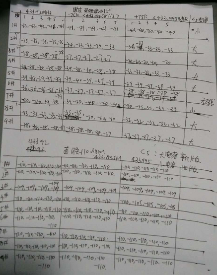
1. RX Sensitivity testing
After the antenna and matched circuit are installed, there is 10 dB difference between the good machine and the good one. Obviously there is a problem in matching, so the matching components need to be modified.
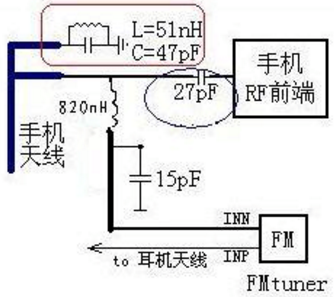
2. Antenna matching circuit
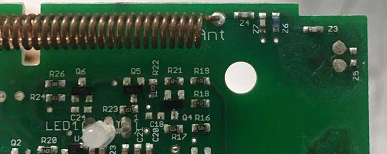
Z3, Z4 - 8p Changde value -2p, 4p ,4.7P ,5P, 7P
Z7 - 5.6p immutable
Z6 - 8.2nH Changde value- 1n 2n 2.5n 4n --2.5n is ok
we have three problems now:
1. Some of the high frequency ends have low sensitivity, which is temporarily analyzed as the defect of IC incoming materials
2. There is no way to detect the bad product with the induction sensitivity of the finished product. Even if it is measured at 3 points, the bad product cannot be extracted normally
3. The new product module is slightly less sensitive than the old one. The antenna matching component may need to be modified, but project 2 antenna problem must be completed
3. Crystal oscillator test
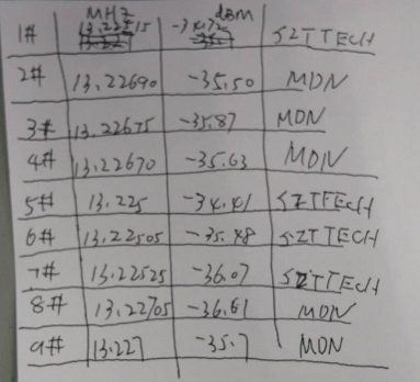
Comparison with SFT Tech sample,ES3704-01-101 Miden MDN-CRY-13225 frequency value exceed the upper limit.

The resonant frequency point of the antenna input loop is not at 433.9mhz (the central frequency point). Component error is one of the reasons, which results in high receiving sensitivity and low sensitivity.
If you have a network analyzer, you can add a 433.92m input signal to the antenna and a Z3 capacitor to the output and directly measure the attenuation dB.If the resonant point of the matching network is at 433.92MHZ, the attenuation is minimal.This is the optimal inductance, capacitance.