前面分析了启动脚本、Makefile、mkconfig,接下来就是uboot的start.S这个启动代码了,下面是本章的平台介绍:
单板:迅为4412开发板(Exynos 4412)
SDRAM:1G
EMMC:4G
Exynos 4412的启动过程可以在数据手册的Booting Sequence找到,下面只截取关键部分:
Exynos 4412 has 64 KB ROM (iROM) and 256 KB SRAM (iRAM) as internal memory.
You can select the booting device from the following list:
1. General NAND flash memory
2. SD/MMC memory card
3. eMMC memory
4. USB deviceAt the system reset, the program execution starts at iROM. The system reset may be asserted not
only on booting time, but also on wakeup from low power modes. Therefore, the boot loader code executes appropriate processes according to the reset status. Refer to Figure 5-1 for more information.The boot loader is comprises the first and the second boot loaders. The characteristics of these boot loaders are:
1. iROM: It is a small and simple code to initiate SOC. It is implemented on internal ROM of SOC.
2. First boot loader (BL1): It is chip-specific and stored in external memory device.
3. Second boot loader (BL2): It is platform-specific and stored in external memory device. User should build and store this in an external memory device. It is not provided by Samsung.
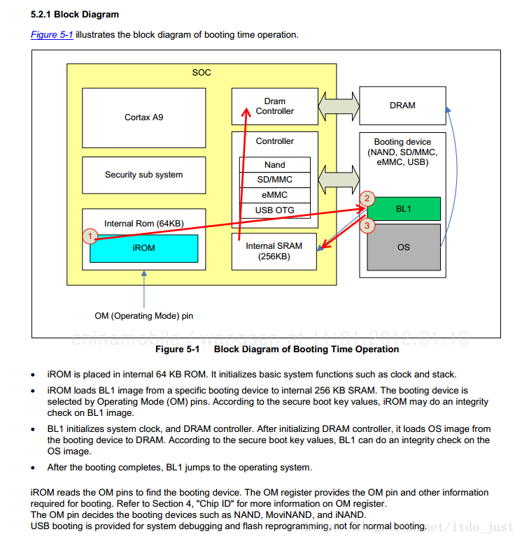
从文字和图片可以总结出如下几点:
BL0:这段是固化的代码放置在 64K 的 iROM 里面,负责初始化基本的系统功能比如时钟和栈,并且加载 BL1 到内部 256KB 的 SRAM。
BL1:这段代码由三星提供,也更改不了,BL0 会根据 OM 引脚来判断当前 booting 设备是哪个,可以是 NAND_FLASH、SD卡、EMMC、USB设备,从选定好的设备中加载 BL1,BL1 主要负责初始化系统时钟和 DRAM 控制器,然后从 booting 设备中加载 OS 到 DRAM 中去运行,这里的 OS 其实就是指 BL2,DRAM 指的则是外部的 SDRAM。
BL2:BL2 的主要功能是去加载我们的 UBOOT 代码,此后 UBOOT 运行在 DRAM上, 同样加载的时候也需要校验,这里需要将 uboot.bin 合并(merge)进BL2里面,在迅为的启动脚本里面有描述,如下:
cat E4412.S.BL1.SSCR.EVT1.1.bin E4412.BL2.TZ.SSCR.EVT1.1.bin all00_padding.bin u-boot.bin E4412.TZ.SSCR.EVT1.1.bin > u-boot-iTOP-4412.bin做好了一切准备以后就开始执行 start.S 了,这里标题指的第一阶段基本上都是用汇编去实现的,主要负责硬件的初始化,第二阶段都是C代码,实现一些比较复杂的内容,下一章节描述。
以 start.S 的代码开始描述:
.word 0x2000
.word 0x0
.word 0x0
.word 0x0

/*
  globl就是相当于C语言中的Extern,声明此变量,并且告诉链接器此变量是全局的,外部可以访问
  指定入口为_start
  u-boot.lds里面定义了ENTRY(_start),即指定入口为_start
 */
.globl _start

/* 跳转到reset,这里的代码地址是00000010 */
_start: b   reset
/*
  ARM是RISC结构,数据从内存到CPU之间的移动只能通过L/S指令来完成,也就是ldr/str指令。
  比如想把数据从内存中某处读取到寄存器中,只能使用ldr
  将_undefined_instruction这个地址处的word(一字节)定义的值赋给pc。

  ARM体系结构规定在上电复位的起始位置必须有8条连续的跳转指令,
  通过硬件来实现。它们就是异常向量表。ARM在上电复位后是从0x0开始启动,
  如果bootloader存在,则是从_start开始执行上面的跳转没有执行。
  设置异常向量表的作用是识别bootloader,以后每当系统有异常出现时,
  cpu会根据异常号从内存0x0处开始查找并做相应的处理
  下面8条即设置异常中断向量表
 */
    ldr pc, _undefined_instruction
    ldr pc, _software_interrupt
    ldr pc, _prefetch_abort
    ldr pc, _data_abort
    ldr pc, _not_used
    ldr pc, _irq
    ldr pc, _fiq

/*
当有异常出现ARM会自动执行以下步骤:

1 将下一条指令的地址存放在连接寄存器LR(通常是R14).---保存位置

2 将相应的CPSR(当前程序状态寄存器)复制到SPSR(备份的程序状态寄存器)中

3 根据异常类型,强制设置CPSR运行模式位

4 强制PC从相应异常向量地址取出下一条指令执行,从而跳转到异常处理函数中执行
 */

_undefined_instruction:
    .word undefined_instruction//“未定义指令”的时候,系统所要去执行的代码。
_software_interrupt:
    .word software_interrupt//软件中断
_prefetch_abort:
    .word prefetch_abort//预取指错误
_data_abort:
    .word data_abort//数据错误
_not_used:
    .word not_used//未定义
_irq:
    .word irq//(普通)中断
_fiq:
    .word fiq//快速中断
_pad:
    .word 0x12345678 /* now 16*4=64 */

.global _end_vect
_end_vect:
/* 接下来的代码,都要16字节对齐,不足之处,用0xdeadbeef填充 */
    .balignl 16,0xdeadbeef

_TEXT_BASE:
/* _TEXT_BASE是一个标号地址,在board\samsung\smdkc210中定义,通过反汇编或路径可得知为"0xc3e00000" */
    .word   TEXT_BASE
_TEXT_PHY_BASE:
    .word   CFG_PHY_UBOOT_BASE /* 反汇编得知为:43e00000 */

.globl _armboot_start
_armboot_start:
    /* 此含义可用C语言表示为:*(_armboot_start) = _start */
    .word _start

/* 以下这些地址跟u-boot.lds一一对应,声明地址标号 */
.globl _bss_start
_bss_start:
    /* bss段的起始地址 */
    .word __bss_start

.globl _bss_end
_bss_end:
    /* bss段的结束地址 */
    .word _end

/* 相当于一个无参数的宏cache_invalidate_dcache_v7,也就相当于一个函数了,似乎和cache有关,暂不细究 */
    .macro  cache_invalidate_dcache_v7
    MRC     p15, 1, r0, c0, c0, 1      @ read Cache Level ID register (clidr)
    ANDS    r3, r0, #0x7000000         @ extract level of coherency from clidr
    MOV     r3, r3, lsr #23            @ left align level of coherency bit field
    BEQ     finished_inval             @ if loc is 0, then no need to clean

    MOV     r10, #0                    @ start clean at cache level 0 (in r10)
loop_1:
    ADD     r2, r10, r10, lsr #1       @ work out 3x current cache level
    MOV     r1, r0, lsr r2             @ extract cache type bits from clidr
    AND     r1, r1, #7                 @ mask of the bits for current cache only
    CMP     r1, #2                     @ see what cache we have at this level
    BLT     skip_inval                 @ skip if no cache, or just i-cache
    MCR     p15, 2, r10, c0, c0, 0     @ select current cache level in cssr
    MOV     r1, #0
    MCR     p15, 0, r1, c7, c5, 4      @ prefetchflush to synch the new cssr&csidr
    MRC     p15, 1, r1, c0, c0, 0      @ read the new csidr
    AND     r2, r1, #7                 @ extract the length of the cache lines
    ADD     r2, r2, #4                 @ add 4 (line length offset)
    LDR     r6, =0x3ff
    ANDS    r6, r6, r1, lsr #3         @ find maximum number on the way size
    CLZ     r5,r6                       @ DCI 0xE16F5F16 , find bit position of way size increment
    LDR     r7, =0x7fff
    ANDS    r7, r7, r1, lsr #13        @ extract max number of the index size
loop_2:
    MOV     r8, r6                     @ create working copy of max way size
    loop_3:
    ORR     r11, r10, r8, lsl r5       @ factor way and cache number into r11
    ORR     r11, r11, r7, lsl r2       @ factor index number into r11
    MCR     p15, 0, r11, c7, c6, 2     @ invalidate by set/way
    SUBS    r8, r8, #1                 @ decrement the way
    BGE     loop_3

    SUBS    r7, r7, #1                 @ decrement the index
    BGE     loop_2
skip_inval:
    ADD     r10, r10, #2               @ increment cache number
    CMP     r3, r10
    BGT     loop_1
finished_inval:
    .endm

/*
 * the actual reset code
 */

reset:
/* 首先进入SVC管理模式,为什么要进行SVC管理模式而不是其它模式,主要因为SVC模式比其他模式有更多的硬件访问权限,并且多了影子寄存器,可以访问的硬件资源更多,详情:http://www.360doc.com/content/13/0514/11/7245213_285318786.shtml */

/*
 * MRS{条件} 通用寄存器,程序状态寄存器(CPSR或SPSR)
 * mrs :程序状态寄存器访问指令
 * 通用寄存器  程序状态寄存器(CPSR或SPSR)
 * 读取CPSR程序状态寄存器,保存到R0中
 */
    mrs r0, cpsr

/*
 * bic :BIC{条件}{S} 目的寄存器,操作数1,操作数2,
 * BIC指令用于清除操作数1的某些位,并把结果放置到目的寄存器中。操作数1应是一个寄存器
 * 操作数2可以是一个寄存器,被移位的寄存器,或一个立即数。操作数2为32位的掩码,如果在掩码中设置了某一
 * 位,则清除这一位。未设置的掩码位保持不变。
 * 0x1f=00011111,相当于清除低5位,刚好是模式位。
 */
    bic r0, r0, #0x1f

/*
 * ORR{条件}{S} 目的寄存器,操作数1,操作数2
 * ORR指令用于在两个操作数上进行逻辑或运算,并把结果放置到目的寄存器中。操作数1应是一个寄存器,操作数
 * 2可以是一个寄存器,被移位的寄存器,或一个立即数。该指令常用于设置操作数1的某些位。
 * 0xd3=11010011
 * 将r0与0xd3算数或运算,然后将结果给r0,即把r0的bit[7:6]和bit[4]和bit[2:0]置为1。
 */
    orr r0, r0, #0xd3

  /*
   * MSR{条件} 程序状态寄存器(CPSR或SPSR)_<域>,操作数
   * MSR指令用于将操作数的内容传送到程序状态寄存器的特定域中
   * 将r0中的值赋给状态寄存器cpsr
   */
    msr cpsr,r0

cache_init:
    /* mrc: 从协处理器读寄存器数据到ARM处理器的R0里面 */
    mrc p15, 0, r0, c0, c0, 0   @ read main ID register
    and r1, r0, #0x00f00000 @ variant
    and r2, r0, #0x0000000f @ revision
    orr r2, r2, r1, lsr #20-4   @ combine variant and revision
    cmp r2, #0x30
    mrceq   p15, 0, r0, c1, c0, 1   @ read ACTLR
    orreq   r0, r0, #0x6        @ Enable DP1(2), DP2(1)
    mcreq   p15, 0, r0, c1, c0, 1   @ write ACTLR

    /*
    CP15系统控制协处理器,CP15有很多个寄存器分别叫做寄存器0(Register 0),到寄存器15(Register 15)
    CP15 —系统控制协处理器 (the system control coprocessor)他通过协处理器指令MCR和MRC提供具体的寄存器来配置和控制caches、MMU、保护系统、配置时钟模式(在bootloader时钟初始化用到)
    CP15的寄存器只能被MRC和MCR(Move to Coprocessor from ARM Register )指令访问
     */
    /* Invalidate L1 I/D */
    mov r0, #0          @ set up for MCR
    /* 清空指令和数据的TLB */
    mcr p15, 0, r0, c8, c7, 0   @ invalidate TLBs
    /* 清除指令缓存ICache */
    mcr p15, 0, r0, c7, c5, 0   @ invalidate icache

    /* disable MMU stuff and caches */
    mrc p15, 0, r0, c1, c0, 0
    /* 此行代码是将r0的值,即0,写入到CP15的寄存器1中,向bit[0]写入0,即关MMU */

    bic r0, r0, #0x00002000 @ clear bits 13 (--V-)/* 清除bit[13],异常寄存器基地址 */
    bic r0, r0, #0x00000007 @ clear bits 2:0 (-CAM)/* 清除bit[2-0],关闭Dcache */
    orr r0, r0, #0x00001000 @ set bit 12 (---I) Icache/* 设置bit[12],开启指令缓存Icache */
    orr r0, r0, #0x00000002 @ set bit 1  (--A-) Align/* 设置bit[1],打开数据地址对齐的错误检查,即如果数据地址为非法(奇数?)地址,就报错 */
    orr r0, r0, #0x00000800 @ set bit 11 (Z---) BTB
    mcr p15, 0, r0, c1, c0, 0
#endif

    /* Read booting information */
    /* 这个寄存器就是去读取OM(从哪启动)寄存器的值 */
    ldr r0, =POWER_BASE /* 将地址0x10020000中的值放入r0 */
    ldr r1, [r0,#OMR_OFFSET] /* 将存储器地址为r0+OMR_OFFSET(0x10020000)的字数据读入寄存器R1 */
    bic r2, r1, #0xffffffc1 /* 清除r1这个寄存器的bit[0]和bit[6:31],把结果放入r2 */

    /* NAND BOOT */
    cmp     r2, #0xA
        moveq   r3, #BOOT_ONENAND//如果等于0xA了,执行这个将BOOT_ONENAND(0x1)存到R3

    /* SD/MMC_CH2 BOOT */
    cmp     r2, #0x4
        moveq   r3, #BOOT_MMCSD //如果等于0x4了,执行这个将BOOT_MMCSD(0x3)存到R3

    /* eMMC43_CH0/USB BOOT */
    cmp     r2, #0x6
    moveq   r3, #BOOT_EMMC43 //如果等于0x6了,执行这个将BOOT_EMMC43(0x6)存到R3

    /* eMMC44_CH4/SDMMC_CH2 BOOT */
    cmp     r2, #0x28
    moveq   r3, #BOOT_EMMC441 //如果等于0x28了,执行这个将BOOT_EMMC43(0x7)存到R3

    /*
    User-defined information register. By asserting XnRESET pin, PMU clears INFORM0 to 3 registers
    */
    ldr r0, =INF_REG_BASE /* 将配置写入相应的寄存器 */
    str r3, [r0, #INF_REG3_OFFSET]

    /*
     * Go setup Memory and board specific bits prior to relocation.
     */
     /* 这段等下单独截出来 */
    bl  lowlevel_init   /* go setup pll,mux,memory */

    ldr r0, =0x1002330C  /* PS_HOLD_CONTROL register */
    ldr r1, =0x00005300  /* PS_HOLD output high */
    str r1, [r0]

    /* get ready to call C functions */
    ldr sp, _TEXT_PHY_BASE  /* setup temp stack pointer 43e00000*/
    sub sp, sp, #12
    mov fp, #0          /* no previous frame, so fp=0 */

    /* 如果已经在DRAM里面跑了就不需要重载了,实际上SDRAM在BL1的时候就初始化了,所以uboot已经运行在了SDRAM上,但具体在哪运行可能不是我们想定义的地址,所以还是得重载。下面会进行判断是否重载
     */
    ldr r0, =0xff000fff

    /*
      bic指令用于清除操作数1的某些位,并把结果放置到目的寄存器中
      清除pc指针的低24位和高16位,其他位保持不变,即[24:47]不变
      判断uboot是不是在我们想要的位置上,如果不是就重载uboot到指定位置
     */
    bic r1, pc, r0      /* r0 <- current base addr of code 当前PC地址*/
    ldr r2, _TEXT_BASE      /* r1 <- original base addr in ram  代码段在内存中的位置*/
    bic r2, r2, r0      /* r0 <- current base addr of code */
    cmp     r1, r2                  /* compare r0, r1                  */
    beq     after_copy      /* r0 == r1 then skip flash copy   */
    /*
    这里不相等代表当前PC不在该有的位置上,可能是因为UBOOT代码前面还有BL2的代码,现在不需要BL2了,所以重载uBOOT到0地址
   */

    /* light led2 如果需要重载则点亮LED作为指示 */
    ldr r0, =0x11000104  /* GPL2(0)  */
    ldr r1, =0x00000001  /* GPL2(0 set output   */
    str r1, [r0]

    ldr r0, =0x11000100  /* GPL2(0)  */
    ldr r1, =0x00000001  /* GPL2(0 output high  */
    str r1, [r0]

    /* wait us 延时 */
    mov r1, #0x10000
9:  subs    r1, r1, #1
    bne 9b

    ldr r0, =INF_REG_BASE /* 读出寄存器值,可知从哪里启动的 */
    ldr r1, [r0, #INF_REG3_OFFSET]

    /* 这里以EMMC启动为例,不一一列出各个选项了 */
    ....

    /* eMMC43_CH0/USB BOOT */
    cmp     r1, #BOOT_EMMC43
    beq     emmc_boot

    ....

emmc_boot:
#if defined(CONFIG_CLK_1000_400_200) || defined(CONFIG_CLK_1000_200_200) || defined(CONFIG_CLK_800_400_200)
    ldr r0, =CMU_BASE
    ldr r2, =CLK_DIV_FSYS1_OFFSET /* 设置分频 */
    ldr r1, [r0, r2]
    orr r1, r1, #0x3 /* 进行或运算  DOUTMMC0 = MOUTMMC0/(3 + 1) */
    str r1, [r0, r2]
#endif
    bl  emmc_uboot_copy /* 确定重定位地址及大小 */
    b   after_copy      /* 重定位代码 */

#if defined(CONFIG_ENABLE_MMU)
enable_mmu: /* 使能MMU */
    /* enable domain access */
    ldr r5, =0x0000ffff
    mcr p15, 0, r5, c3, c0, 0       @load domain access register

    /* Set the TTB register */
    ldr r0, _mmu_table_base
    ldr r1, =CFG_PHY_UBOOT_BASE
    ldr r2, =0xfff00000
    bic r0, r0, r2
    orr r1, r0, r1
    mcr p15, 0, r1, c2, c0, 0

    /* Enable the MMU */
mmu_on:
    mrc p15, 0, r0, c1, c0, 0
    orr r0, r0, #1
    mcr p15, 0, r0, c1, c0, 0
    nop
    nop
    nop
    nop
#endif

#ifdef CONFIG_EVT1
    /* store DMC density information in u-boot C level variable */
    ldr r0, = CFG_UBOOT_BASE /* 把uboot地址0x43e00000写入r0 */
    sub r0, r0, #4 /* uboot的代码基地址减去4后的字数据写入r1*/
    ldr r1, [r0]
    ldr r0, _dmc_density /* 0xFFFFFFFF = 4G的EMMC */
    str r1, [r0]  /* C表示: *r0 = r1 将这个字数据保存到EMMC? */
#endif


skip_hw_init:
    /* Set up the stack */
stack_setup:
/* 内存中uboot的区域空间(2M),减去的4K用于存放bd信息结构体数据 */
    ldr sp, =(CFG_UBOOT_BASE + CFG_UBOOT_SIZE - 0x1000)//0x43e00000 + 2M - 4K

/* 请 BSS 段 */
clear_bss:
    ldr r0, _bss_start      /* find start of bss segment        */
    ldr r1, _bss_end        /* stop here                        */
    mov     r2, #0x00000000     /* clear                            */

/* 循环清除BSS段的内容,即置0 */
clbss_l:
    str r2, [r0]        /* clear loop... */
    add r0, r0, #4
    cmp r0, r1
    ble clbss_l

    ldr pc, _start_armboot

_start_armboot:
    .word start_armboot /* 进入这个C函数后就属于第二阶段的代码了,汇编到此结束 */
补充说明一下 lowlevel_init 做了什么:
#define check_mem /* 判断是否需要重载的宏 */

    .globl lowlevel_init
lowlevel_init:
    /* use iRAM stack in bl2 */
    /* 设置成iram的栈保险一些,因为不用初始化,uboot刚开始并不知道dram是否初始化了,所以使用iram */
    ldr sp, =0x02060000

    push    {lr}

    /* check reset status  */
    ldr     r0, =(INF_REG_BASE + INF_REG1_OFFSET)//INFORM1: 0x10020800+4
    ldr     r1, [r0]

    /* AFTR wakeup reset */
    ldr r2, =S5P_CHECK_DIDLE //0xBAD00000
    cmp r1, r2
    beq exit_wakeup

    /* Sleep wakeup reset */
    ldr r2, =S5P_CHECK_SLEEP//0x00000BAD
    cmp r1, r2
    beq wakeup_reset

    /* PS-Hold high PS_HOLD_CONTROL */
    ldr r0, =0x1002330c
    ldr r1, [r0]
    orr r1, r1, #0x300  /* r1和0x300或运算 */
    str r1, [r0] /* r1写回地址r0 */

    /* 0x0 = Disables Pull-up/Pull-down */
    ldr     r0, =0x11000c08
    ldr r1, =0x0
    str r1, [r0]/* r1写回地址r0 */

    /* Clear  MASK_WDT_RESET_REQUEST  */
    ldr r0, =0x1002040c
    ldr r1, =0x00
    str r1, [r0]

    #ifdef check_mem /* 检测是否需要重载 */
    /* when we already run in ram, we don't need to relocate U-Boot.
     * and actually, memory controller must be configured before U-Boot
     * is running in ram.
     */
    ldr r0, =0xff000fff
    bic r1, pc, r0      /* r0 <- current base addr of code */
    ldr r2, _TEXT_BASE      /* r1 <- original base addr in ram */
    bic r2, r2, r0      /* r0 <- current base addr of code */
    cmp     r1, r2                  /* compare r0, r1                  */
    beq     1f          /* r0 == r1 then skip sdram init   */
#endif
    /* 这里需要重载所以要进行如下初始化 */
    /* Memory initialize */
    bl mem_ctrl_asm_init

    /* init system clock */
    bl system_clock_init

    bl tzpc_init
    b   1f

1:
    /*wenpin.cui: headphone and sw uart switch init*/
    ldr r0, =0x11000C44
    ldr r1, [r0]
    and r1, r1, #0x4
    cmp r1, #0x4    /*uart*/
    beq out

    ldr     r0, =0x11400084  /* GPC1(0)  */
    ldr     r1, [r0]    /* read GPC1DAT status*/
    orr r1, r1, #0x1    /* GPC1(0) output high  */
    str     r1, [r0]

    ldr     r0, =0x11400080  /* GPC1(0)  */
    ldr r1, [r0]
    and r1, r1, #0xfffffff0
    orr     r1, r1, #0x1    /* GPC1(0) output  */
    str     r1, [r0]
out:
    /* for UART */
    bl uart_asm_init

    bl onenandcon_init

    /* Print 'K' */
    ldr r0, =ELFIN_UART_CONSOLE_BASE
    ldr r1, =0x4b4b4b4b
    str r1, [r0, #UTXH_OFFSET]

    /* 2010.08.27 by icarus : for temporary 3D clock fix */
    ldr r1, =0x1
    ldr r2, =0x1003C22C
    str r1, [r2]
    ldr r1, =0x2
    ldr r2, =0x1003C52C
    str r1, [r2]

    /* 2010.10.17 by icarus : for temporary MFC clock fix */
    ldr r1, =0x3
    ldr r2, =0x1003C528
    str r1, [r2]

/*
其中保存的寄存器中,也包括lr的值(因为用bl指令进行跳转的话,那么之前的pc的值是存在lr中的),
然后在子程序执行完毕的时候,再把堆栈中的lr的值pop出来,赋值给pc,这样就实现了子函数的正确的返回。
*/
    pop {pc}
上面的代码都进行了注解,可以总结uboot启动第一阶段的所做的事如下:
中断向量地址定义
uboot代码段、数据段、bss段定义
上电进入复位中断处理
把CPU的工作模式设置为SVC32模式
清空指令和数据的TLB
清除指令缓存ICache
关MMU
关Dcache
读取boot启动方式
选择相应boot(NAND/SD/EMMC)启动模式
进入 lowlevel_init :set sp in bl2、Memory initialize、init system clock 、uart_asm_init、onenandcon_init
设置SDRAM栈,判断是否需要重载,需要重载则点灯,读取启动信息判断从哪里复制bin,进行重载,复制uboot到指定地址即重定位uboot,使能MMU,保存 dmc density 信息,设置栈,腾出4K存放bd信息,清BSS段,执行 “start_armboot”。
针对上面可能还有些疑问:
问:根据手册,IROM初始化了系统时钟和栈,BL1初始化了系统时钟和DRAM,是不是初始化这些后 UBOOT 可以不用再次初始化了呢?直接操作即可?
答:虽然说BL1初始化了DRAM和时钟,但是这些设置我们并不清楚,也不知道是不是处在最优状态,所以最好的解决方式就是再初始化一遍,设置为我们想要的配置值
不了解各个段区别的可以看下下面的 TIPS
TIPS:
- BSS段
在采用段式内存管理的架构中,BSS段(bss segment)通常是指用来存放程序中未初始化的全局变量的一块内存区域。BSS是英文Block Started by Symbol的简称。BSS段属于静态内存分配。- 数据段
在采用段式内存管理的架构中,数据段(data segment)通常是指用来存放程序中已初始化的全局变量的一块内存区域。数据段属于静态内存分配。- 代码段
在采用段式内存管理的架构中,代码段(text segment)通常是指用来存放程序执行代码的一块内存区域。这部分区域的大小在程序运行前就已经确定,并且内存区域属于只读。在代码段中,也有可能包含一些只读的常数变量,例如字符串常量等