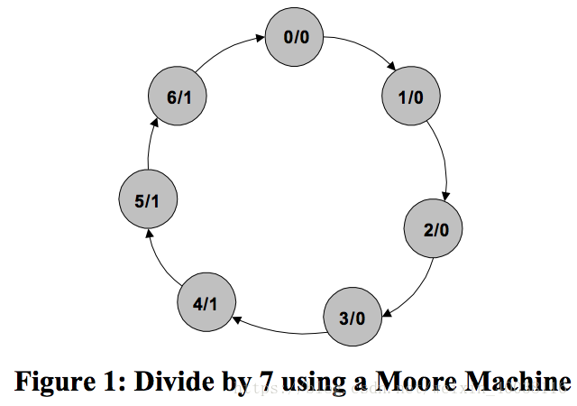
1. Odd integer division(not 50% duty cycle)
Design Moore machine (take "7" as example)
2. Odd integer division with 50% duty cycle
Conceptually, the easiest way to create an odd divider with a 50% duty cycle is to generate two
clocks at half the desired output frequency with a quadrature-phase relationship (constant 90°
phase difference between the two clocks).
You can then generate the output frequency by exclusive-ORing the two waveforms together.
Because of the constant 90° phase offset, only one transition occurs at a time on the input of the
exclusive-OR gate, effectively eliminating any glitches on the output waveform.
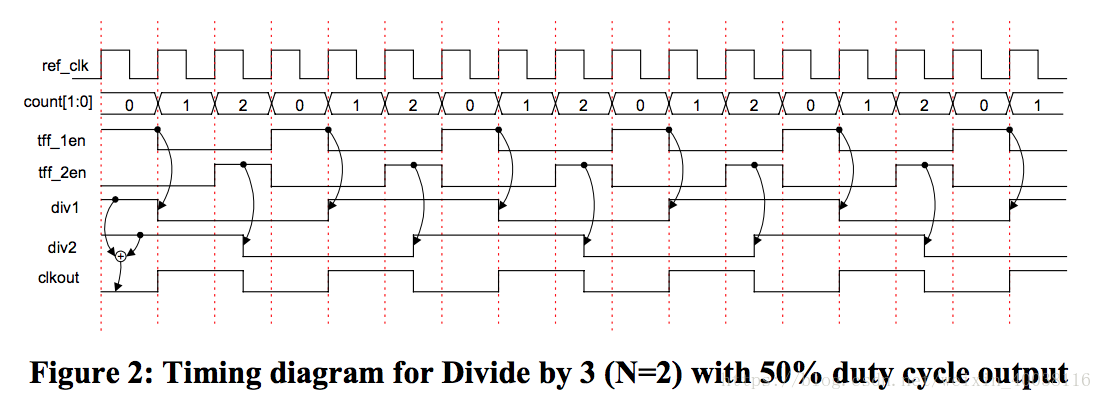
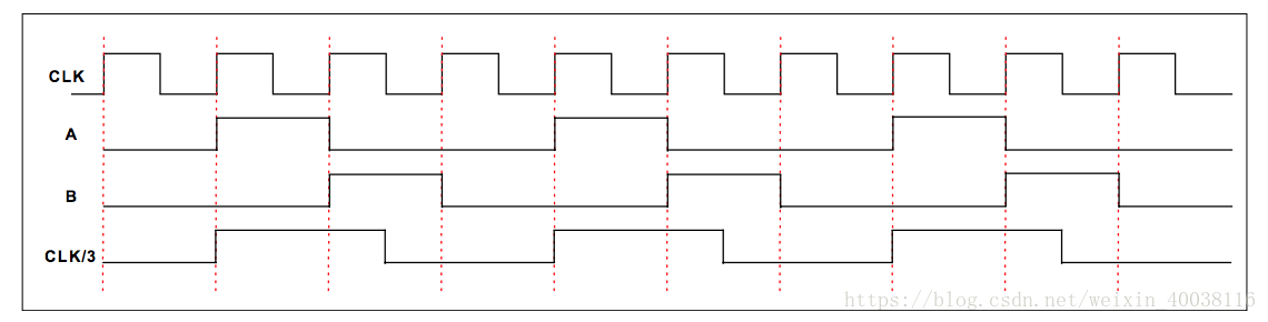
For Divider that counts to odds N (take "3" as example)
<1>. Create a counter that counts from 0 to N-1.
<2>. Define two toggle flip-flops and generate their enables as follows:
tff1_en: T FF1 enable when the counter value = 0;
tff1_en: T FF1 enable when the counter value = (N+1)/2;
<3>. div1: output of FF1 (triggered by rising edge of clk)
div2: output of FF1 (triggered by falling edge of clk)
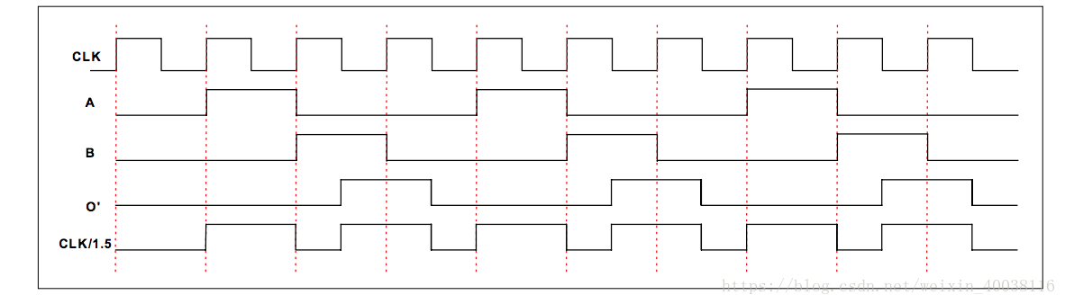
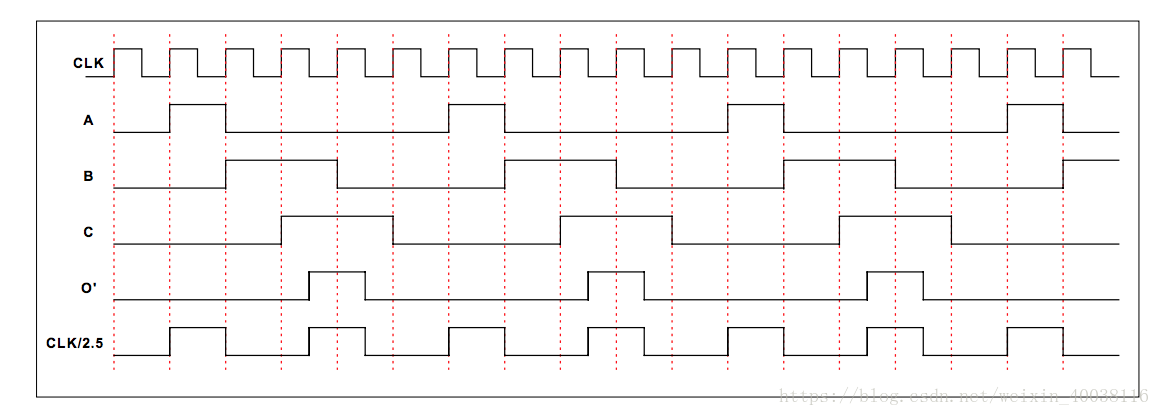
3. Non-integer division (duty cycle not 50%)
Below circuit does not generate the output clock with 50% duty cycle. You cannot get anything better than 40%-60% with a digital circuit.
<1>. Divide by 1.5
Divide by 1.5 is generated by first generating a Divide by 3 circuit


<2>. Divide by 2.5


<3>. Divide by 3 with 50% duty cycle:

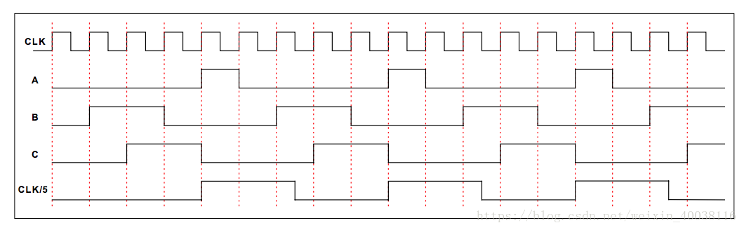
<4>. Divide by 5 with 50% duty cycle:

Reference: https://www.mikrocontroller.net/attachment/177198/Clock_Dividers_Made_Easy.pdf