#include <inc/x86.h>
#include <inc/elf.h>

/**********************************************************************
 * This a dirt simple boot loader, whose sole job is to boot		// 一个简单的 Bootloader,用于读取内核
 * an ELF kernel image from the first IDE hard disk.
 *
 * DISK LAYOUT
 *  * This program(boot.S and main.c) is the bootloader.  It should	// Bootloader 储存在第一个扇区
 *    be stored in the first sector of the disk.
 *
 *  * The 2nd sector onward holds the kernel image.		// 第二个扇区开始储存内核
 *
 *  * The kernel image must be in ELF format.		// 内核必须为 ELF 格式
 *
 * BOOT UP STEPS
 *  * when the CPU boots it loads the BIOS into memory and executes it
 *
 *  * the BIOS intializes devices, sets of the interrupt routines, and
 *    reads the first sector of the boot device(e.g., hard-drive)
 *    into memory and jumps to it.
 *
 *  * Assuming this boot loader is stored in the first sector of the
 *    hard-drive, this code takes over...
 *
 *  * control starts in boot.S -- which sets up protected mode,
 *    and a stack so C code then run, then calls bootmain()
 *
 *  * bootmain() in this file takes over, reads in the kernel and jumps to it.		// bootmain 函数读取并跳转到内核
 **********************************************************************/

#define SECTSIZE	512	// 扇区大小 512bytes
#define ELFHDR		((struct Elf *) 0x10000) // Makefrag 文件中设置内核起始地址为 0x10000
void bootmain(void)
{
struct Proghdr *ph, *eph;
// read 1st page off disk
readseg((uint32_t) ELFHDR, SECTSIZE*8, 0); // 读取内核的前 2048bytes 到内存
// is this a valid ELF?
if (ELFHDR->e_magic != ELF_MAGIC) // 判断 magic number
goto bad;
// load each program segment (ignores ph flags)
ph = (struct Proghdr *) ((uint8_t *) ELFHDR + ELFHDR->e_phoff); // 指向 program header table 头部
eph = ph + ELFHDR->e_phnum; // 指向 program header table 尾部
for (; ph < eph; ph++)
// p_pa is the load address of this segment (as well
// as the physical address)
readseg(ph->p_pa, ph->p_memsz, ph->p_offset); //逐段读入内存
// call the entry point from the ELF header
// note: does not return!
((void (*)(void)) (ELFHDR->e_entry))(); // 调用内核程序
bad:
outw(0x8A00, 0x8A00);
outw(0x8A00, 0x8E00);
while (1)
/* do nothing */;
}#define ELF_MAGIC 0x464C457FU /* "\x7FELF" in little endian */ // elf.h 部分内容
struct Elf { // ELF header
uint32_t e_magic; // must equal ELF_MAGIC
uint8_t e_elf[12]; // magic number 的相关信息
uint16_t e_type; // 文件类型,1 = 可重定位的,2 = 可执行的,3 = 共享的,4 = 核心的
uint16_t e_machine; // 机器的指令集结构,例如 0x03 代表 x86,0x08 代表 MIPS 等
uint32_t e_version; // ELF 文件版本
uint32_t e_entry; // 程序入口的地址
uint32_t e_phoff; // program header table 的偏移地址
uint32_t e_shoff; // section header table 的偏移地址
uint32_t e_flags; // 与机器的架构相关的值
uint16_t e_ehsize; // ELF header 大小
uint16_t e_phentsize; // program header table 条目大小
uint16_t e_phnum;< // program header table 条目数量
uint16_t e_shentsize; // section header table 条目大小
uint16_t e_shnum;< // section header table 条目数量
uint16_t e_shstrndx; // 含有 section 名称的条目索引
};
struct Proghdr { // program header table 程序头表
uint32_t p_type; // program header 类型
uint32_t p_offset; // 相对于文件的偏移地址
uint32_t p_va;< // 虚拟地址
uint32_t p_pa;< // 物理地址
uint32_t p_filesz; // 在文件中的大小
uint32_t p_memsz; // 在内存中的大小
uint32_t p_flags; // 相关的标志
uint32_t p_align; // 对齐方式
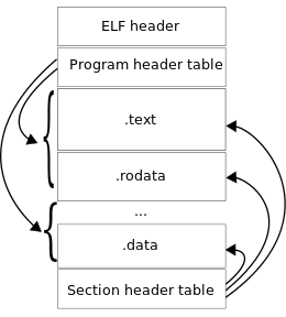
};下图为 ELF 文件结构
第 9 行,判断 magic number,magic number 可以理解为识别文件类型的一段标识,在这里就是 0x7f454c46
// Read 'count' bytes at 'offset' from kernel into physical address 'pa'.
// Might copy more than asked
void readseg(uint32_t pa, uint32_t count, uint32_t offset)
{
	uint32_t end_pa;

	end_pa = pa + count;	//段尾部地址

	// round down to sector boundary
	pa &= ~(SECTSIZE - 1);		// 对齐扇区

	// translate from bytes to sectors, and kernel starts at sector 1
	offset = (offset / SECTSIZE) + 1;	// 可以理解为第几块扇区,这个变量即扇区号

	// If this is too slow, we could read lots of sectors at a time.
	// We'd write more to memory than asked, but it doesn't matter --
	// we load in increasing order.
	while (pa < end_pa) {	// 逐个扇区读入
		// Since we haven't enabled paging yet and we're using
		// an identity segment mapping (see boot.S), we can
		// use physical addresses directly.  This won't be the
		// case once JOS enables the MMU.
		readsect((uint8_t*) pa, offset);
		pa += SECTSIZE;
		offset++;
	}
}hiroshi@Hiroshi-PC:~/6.828/lab/obj/kern$ objdump -p kernel
kernel: 文件格式 elf32-i386
程序头:
LOAD off 0x00001000 vaddr 0xf0100000 paddr 0x00100000 align 2**12
filesz 0x0000712f memsz 0x0000712f flags r-x
LOAD off 0x00009000 vaddr 0xf0108000 paddr 0x00108000 align 2**12
filesz 0x0000a300 memsz 0x0000a944 flags rw-
STACK off 0x00000000 vaddr 0x00000000 paddr 0x00000000 align 2**4
filesz 0x00000000 memsz 0x00000000 flags rwx
还可以发现,第二段的 filesz 与 memsz 是不相同的,这是因为 .bss 节中的全局变量在文件中不占空间,在内存中才分配空间并初始化
如果不明白 readseg 的,可以用其中一个段模拟一遍这个函数
void waitdisk(void)
{
	// wait for disk reaady
	while ((inb(0x1F7) & 0xC0) != 0x40)
		/* do nothing */;
}
void readsect(void *dst, uint32_t offset)
{
// wait for disk to be ready
waitdisk();
outb(0x1F2, 1); // count = 1
outb(0x1F3, offset);
outb(0x1F4, offset >> 8);
outb(0x1F5, offset >> 16);
outb(0x1F6, (offset >> 24) | 0xE0);
outb(0x1F7, 0x20); // cmd 0x20 - read sectors
// wait for disk to be ready
waitdisk();
// read a sector
insl(0x1F0, dst, SECTSIZE/4);
}我们先来看看下面一些关于 ATA 和 LBA 的资料(表格只列出相关内容,这里的寻址方式应该是 28-bit LBA)
| CS1FX- | CS3FX- | DA2 | DA1 | DA0 | Address | READ (DIOR-) | WRITE (DIOW-) |
|---|---|---|---|---|---|---|---|
| 1 | 0 | 0 | 0 | 0 | 0x1F0 | Data | Data |
| 1 | 0 | 0 | 0 | 1 | 0x1F1 | Error register | Features |
| 1 | 0 | 0 | 1 | 0 | 0x1F2 | Sector count | Sector count |
| 1 | 0 | 0 | 1 | 1 | 0x1F3 | Sector number | Sector number |
| 1 | 0 | 1 | 0 | 0 | 0x1F4 | Cylinder low | Cylinder low |
| 1 | 0 | 1 | 0 | 1 | 0x1F5 | Cylinder high | Cylinder high |
| 1 | 0 | 1 | 1 | 0 | 0x1F6 | Drive/head | Drive/head |
| 1 | 0 | 1 | 1 | 1 | 0x1F7 | Status | Command |
| Register | D7 | D6 | D5 | D4 | D3 | D2 | D1 | D0 |
|---|---|---|---|---|---|---|---|---|
| 0x1F3 | LBA7 | LBA6 | LBA5 | LBA4 | LBA3 | LBA2 | LBA1 | LBA0 |
| 0x1F4 | LBA15 | LBA14 | LBA13 | LBA12 | LBA11 | LBA10 | LBA9 | LBA8 |
| 0x1F5 | LBA23 | LBA22 | LBA21 | LBA20 | LBA19 | LBA18 | LBA17 | LBA16 |
| 0x1F6 | 1 | LBA | 1 | DRV | LBA27 | LBA26 | LBA25 | LBA24 |
第一个表中前面的五列为引脚信号,接着是对应的地址,各地址代表的寄存器意义如下:
0x1F3 R/W,数据寄存器
0x1F2 R/W,扇区数寄存器,记录操作的扇区数
0x1F3 R/W,扇区号寄存器,记录操作的起始扇区号
0x1F4 R/W,柱面号寄存器,记录柱面号的低 8 位
0x1F5 R/W,柱面号寄存器,记录柱面号的高 8 位
0x1F6 R/W,驱动器/磁头寄存器,记录操作的磁头号,驱动器号,和寻道方式,前 4 位代表逻辑扇区号的高 4 位,DRV = 0/1 代表主/从驱动器,LBA = 0/1 代表 CHS/LBA 方式
0x1F7 R,状态寄存器,第 6、7 位分别代表驱动器准备好,驱动器忙
0x1F8 W,命令寄存器,0x20 命令代表读取扇区
接下来看代码,在 waitdisk 函数中,while 条件所代表的意义为读取驱动器状态,利用逻辑 AND 取出第 6、7 位,并与 0x40(01000000) 比较,若相等则代表驱动器准备好
接下来看 readsect 函数
第 6 行,由于每次只读取 1 个扇区,所以向扇区数寄存器写入 1
第 7 、8、9 行,写入扇区号、柱面号信息,注意每个函数写入的大小为 1byte
第 10 行,注意 0xE0 = 11100000,代表主驱动器,LBA 寻址方式
第 11 行,向命令寄存器写入读取扇区的命令
第 17 行,读取扇区,具体代码在 x86.h,这段内嵌的汇编代码我看不懂……不过从注释上看就是读取扇区
参考资料:
http://www.mcufan.com/article/ata-interface.pdf
http://www.t13.org/documents/UploadedDocuments/project/d0791r4c-ATA-1.pdf
http://wiki.osdev.org/ATA_PIO_Mode#28_bit_PIO
https://en.wikipedia.org/wiki/Executable_and_Linkable_Format