XILINX MICROPROCESSOR DEBUGER (XMD) REFERENCE GUIDE
This guide was designed to be used with ISE and EDK 9.1. The debugger provided by XILINX (XMD) is a tool that interacts with PowerPC and MicroBlaze microprocessors and allows the debugging of programs and the verification of systems. The debugger program can be used for programs in hardware board, Cycle-Accurate Instruction Set Simulator (ISS) or MicroBlaze Cycle-Accurate Virtual Platform (VP) system.
In order to access the XMD tool within XPS, go to DebugàLaunch XMD or go to Start Menu à Run à XMD.
To see the available commands in XMD, type help in the command line as shown below.
XMD% help
After doing that, a list of the different command types appear as seen in the next figure.
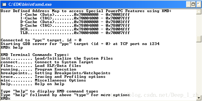
Now, the commands found in each type will be analyzed. To see the commands in each command type, write help and the command type.
XMD% help “command type”
In the following pages, each command in the different commands types will be explained.
Command type: INIT – Load/ Initialize the system files (help init)
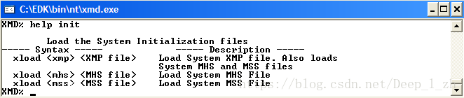
The only command of this type is XLOAD. With this command, a file whose extension could be *.mhs, *.xmp, and *.mss can be loaded. The syntax to use this command is shown below.
XMD% xload <extension file> <file name>
Remember the meaning of the following file extensions:
- MHS (Microprocessor Hardware Specification). This type of file defines hardware specifications for a microchip design created with XILINX Platform Studio (XPS); it includes which devices the hardware can interface with.
- XMP (XILINX Microprocessor project). This type of file is the top-level project file for an EDK design. It is used for project management, and you should not attempt to edit it.
- MMS (Microprocessor Software Specification). This type of file defines what software can be used with a microchip designed with XILINX Platform Studio (XPS)
Command type: CONNECT – Connect to System Target (help connect)

This kind of commands is used to connect to an FPGA prototype platform. In this case, we use this command to connect to the PowerPC in the ML403 board. There are seven commands of this type and their descriptions are listed below.
CONNECT: With this command, the program can connect to the target. There are three types of targets for the XMD: mb, ppc and mdm which mean MicroBlaze, PowerPC and OPB_mdm peripheral respectively. In this case, the PowerPC in the ML403 is used so the connection will be with the ppc. The syntax is shown below.
XMD connect <target (mb, ppc, mdm)> <connect type (sim, stub, hw, mdm)> [options]
For this command, the help option is available in XMD. Since the system of interest is connected to the PowerPC, the following text in XMD should be written.
XMD% help connect pc
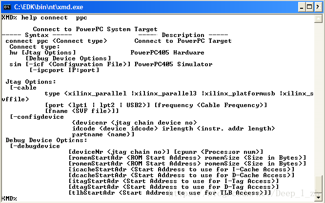
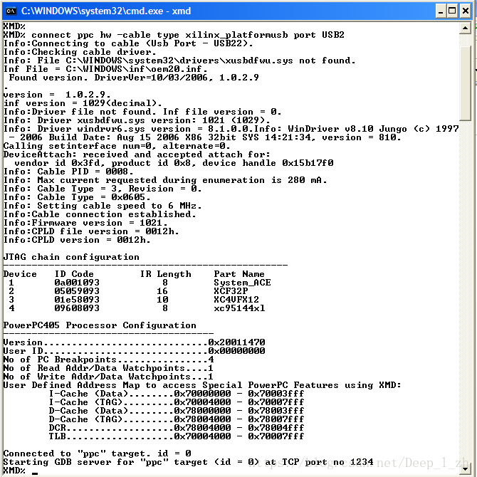
Note in the above figure the options that can be specified by using this command. For example, in the connection type there are two options: the first one implies the usage of hardware and the second one, the usage of a simulator. In this case, the hardware option will be set. In the JTAG options connections, the cable and the port used for the transmission of information must be specified. The option selection depends on the cable connection that is used (which is xilinx_platformusb in this case). The following figure shows an example of the usage of this command.
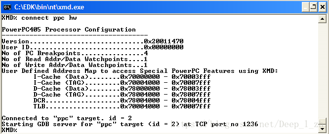
Note that in the following figure, the cable connection is also specified. For this reason, when the connection is established, all the information about the cable and the devices that were found in the connection show up. Since the ML403 has three devices besides the FPGA, the JTAG chain shows the id code of the each device.
VPCONNECT (Virtual platform connect): This command is used to connect to the MicroBlaze virtual platform. Since the PowerPC is use in this guide, this command will not be employed. The syntax is shown below.
XMD% vpconnect mb
VPIO: This command is also used on Virtual Platform only. By writing this command in XMD, the input and output interfaces (UART and GPIO) are started for the virtual platform system.
XMD% vpio
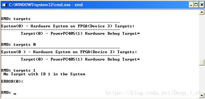
TARGETS: This command lists the information related with the current targets. In this case, we are working with the PowerPC in the FPGA XC4VFX12, so when this option is entered, the information seen in the following figure appears. Note that the FPGA device corresponds to the third device in the board. If there were more than one target, these ones could be specified by writing the targets command followed by the target id as shown below.
XMD% targets
XMD% targets <target ID>
XMD% targets <-system> [system ID]
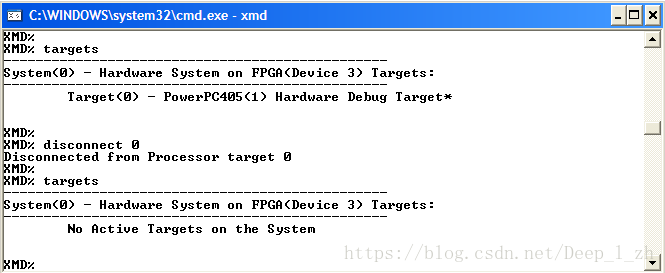
DISCONNECT: Disconnects the systems from the processor. In this case the PowerPC will be disconnected from the system. This command is used by typing the command followed by the target id. The syntax is shown below.
XMD% disconnect <target ID>
The following figure shows the usage of this command. Note that the PowerPC is associated with the target 0 so that the command is followed by the number 0.
Command type: FILES – Load ELF/data files (help files)
There is only one command of this type called dow, that is used to download files. There are three possibilities to do it as shown in the figure below.
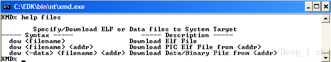
In this case, we use an ELF file so the following syntax will be used.
XMD% dow <ELF filename>
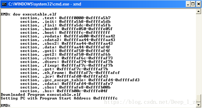
It is important to know that ELF (The Executable and Linking format) is a common standard file format for executables, object code, shared libraries and core dumps. The elf file associated with the c or assembler code used in a specific project, is the executable.elf file. The executable file and the system.bit generate the download.bit. Notice that the latter file is used to program the FPGA with the new system.
The following figure shows the usage of this command. Note that to download the executable.elf file, the source directory has to be specified. Remember that the executable.elf file is in the TestApp_Memory folder in the project. Also note that for this particular project each section is associated to a specific range of addresses which may differ for different projects.
Command type: RUNNING – Program Execution (help running)
The commands in this section will be used more frequently since its usage involves program execution, reading and writing in the registers and the memory.

A detailed explanation of each command is given below.
RUN: like its name implies, runs the program from the start address which can be specified in XPS either manually or by default when using the XPS wizard. In general, the start address is associated with the base address of the memory where the program is going to be stored. The syntax of this command is shown below.
XMD% run
CON (continue): This command continues running the program from its current position or from a specific one. The two modes of operation are shown below
XMD% con
XMD% con 0x365
STP: By using this command, the user can specify the number of instructions that he/she wants to run. If the command is written alone, only 1 instruction will be run; if it is not, it will run the number of instructions that are specified as its argument.
XMD% stp (run 1 instruction)
XMD% stp 8 (run 8 instructions)
CSTP: With this command a user can run a specific number of cycles in the program. The syntax is shown below. Notice that this command is not supported by the PowerPC in ML403 board; this only supports ISS/VP targets.
XMD% cstp
XMD% cstp <number of cycles>
RST (reset): Resets the system. This means that the processor target is reset.
XMD% rst
STOP: This command stops running the program, that is, it stops the target processor.
XMD% stop
RRD (Register Read): The Registers are read when the command rrd is written. This command has the option of specifying the register that is going to be read in two forms. The first one is to write the command followed by the name of the register or by the number associated with this register. The examples of the usage of this command are shown below.
XMD% rrd (read all the registers)
XMD% rrd “register name”. (rrd r3)
XMD% rrd “number of the register” (rrd 3)
The following figure shows the information obtained with this command.
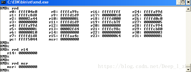
As displayed in the above figure, there are 32 registers that range from r0 to r31. These registers are called the General Purpose Registers (GPRs) and are 32-bits long. The contents of the GPRs can be modified with other commands which will be explained later.
SRRD (Special Register Read): The contents of each register can be read after the command srrd is typed in XMD. Also, specific registers can be read just like with the rrd command.
XMD % srrd
XMD% srrd <register name>
The information displayed after typing the srrd command is shown in the following figure. The registers that appear in the figure are called Special Purpose Registers (SPRs) which are part of the PowerPC architecture and can be accessed by using the mtspr and mfspr commands. By modifying these registers, the interruptions, the timers, and other important functions can be controlled. To see this in detail, look at reference [powerpc405 manual].
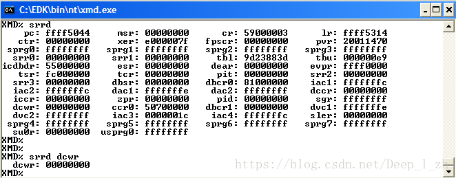
It is important to mention that each SPR has an associated address, and that these addresses are not necessarily consecutive. For example in the Save/ Restore registers, the SRR0 and the SRR1 have as addresses 0x01A and 0x1B respectively, while the SRR2 and the SRR3 have as addresses 0x3DE and 0x3DF respectively. To see the associated address for each SPR see section3-4 of PPC405CR User’s Manual.
In the following table the description of each register is specified.
| Command |
Description |
Command |
Description |
| CCR0 |
Core Configuration Register |
PID |
Process ID |
| CR |
Condition Register |
PIT |
Programmable Interval Timer |
| CTR |
Counter register |
PVR |
Processor Version Register |
| DAC1 |
Data Address Compares |
SGR |
Store Guarded Register |
| DAC2 |
Data Address Compares |
SLER |
Store Little Endian register |
| DBCR0 |
Debug Control Register |
SPRG0 |
SPR General register |
| DBCR1 |
Debug Control Register |
SPRG1 |
SPR General register |
| DBSR |
Debug Status Register |
SPRG2 |
SPR General register |
| DCCR |
Data Cache Cachability Register |
SPRG3 |
SPR General register |
| DCWR |
Data Cache Write-though register |
SPRG4 |
SPR General register |
| DEAR |
Data Exception Address Register |
SPRG5 |
SPR General register |
| DVC1 |
Data Value Compares |
SPRG6 |
SPR General register |
| DVC2 |
Data Value Compares |
SPRG7 |
SPR General register |
| ESR |
Exception Syndrome Register |
SRR0 |
Save/Restore register |
| EVPR |
Exception Vector Prefix Register |
SRR1 |
Save/Restore register |
| FPSCR |
Floating Point Status and Control Register |
SRR2 |
Save/Restore register |
| IAC1 |
Instruction Address Compares |
SRR3 |
Save/Restore register |
| IAC2 |
Instruction Address Compares |
SU0R |
Storage User-defined 0 Register |
| IAC3 |
Instruction Address Compares |
TBL |
Time Base Register (Lower) |
| IAC4 |
Instruction Address Compares |
TBU |
Time Base Register (Upper) |
| ICCR |
Instruction Cache Cachability register |
TCR |
Time Control Register |
| ICDBDR |
Instruction Cache Debug Data Register |
TSR |
Timer Status Register |
| LR |
Link Register |
USPRG0 |
User SPR General Register 0 |
| MSR |
Machine State Register |
XER |
Fixed-Point Exception Register |
|
|
|
ZPR |
Zone Protection Register |
RWR (Register write): With this command the contents of the registers could be modified. To do that, the command has to be written followed by the name of the register and the new value. An example of how to use this command is shown below.
XMD% rwr <register name> <new value>
XMD% rwr pc 0xffff0000 (write in the pc register the value 0xffff0000)
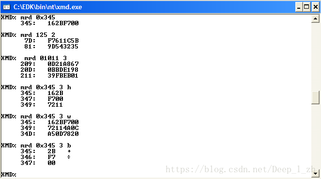
MRD (Memory read): With this command, an address or a group of addresses could be read from the memory. To do so, write the command followed by the start address of the block of memory that is to be read and specify the address range. The following example shows the usage of this command.
XMD% mrd <address>
XMD% mrd <address> <number>
XMD% mrd <address> <number> <variable>
Note that the address could be specified in hexadecimal, decimal or binary format. The variable that represents the number of bytes to read from an address is specified. The letters that could be written to indicate the number of bytes to read from the memory starting from the value in address are h (half word – 2 bytes), w (word 4 bytes) and b (byte). To better understand this, see the examples in the following figure.
MRD_VAR Reads memory corresponding to global variable in the ELF file. The syntax is shown below.
XMD% mrd_var <variable> <ELF file>
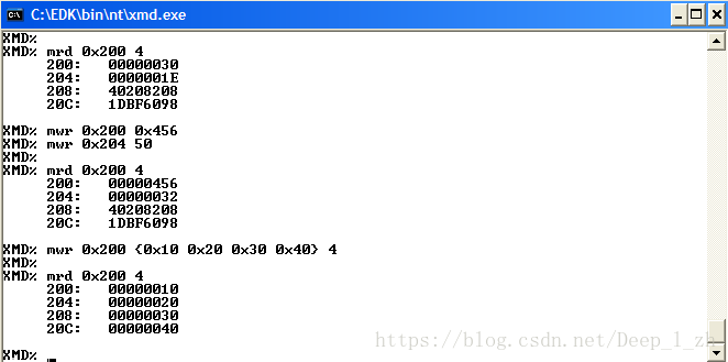
MWR (Memory Write): With this command, a position or a block in the memory can be written. The syntax for the usage of this command can be seen below.
%XMD mwr <address>
%XMD mwr <address> <values> <num>
The following figure shows the usage of this command. It can be seen that different values can be written in a block of the memory. Note also that the values could be specified in a binary, hexadecimal, and word format as seen previously.
Command type: BREAKPOINTS – Setting breakpoints and Watchpoints (help breakpoints)
BPS (Breakpoint sets): This command sets a breakpoint in hardware or software. To set a breakpoint in hardware, the command is written followed by an address. To set a breakpoint in software the command is written followed by a function. Notice that in this case, the last downloaded ELF file is used for function look up. To see the syntax of the command see below.
XMD% bps <address> [sw | hw]
XMD% bps <function> [sw | hw]
WATCH (Set Read/Write Watchpoints): This command is used to compare values of a specific register with the field [data] and in this way, stop the processor. This command is written followed by the variable read or write [r | w] and then the value. The syntax is shown below.
XMD% watch [r | w] <address> [data]
BPR (Breapoint/ Watchpoint Remove): As its name implies, with this command, a specific or all the breakpoints and watchpoints could be removed by the user. There are four different ways of using this command and the syntax is shown below.
XMD% bpr <address> (bpr 0x1234)
XMD% bpr <function> (bpr main)
XMD% bpr <bp id>
XMD% bpr <all> (bpr all)
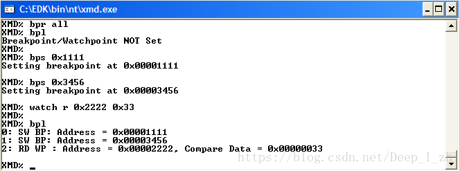
BPL (Breakpoint List): This command shows all the breakpoints and watch points that are currently set previously. The syntax is show below.
XMD% bpl
In the next figure, an example of the usage of the breakpoints commands is shown. First notice that all the breakpoints and watchpoints are removed, second, the breakpoints and the watchpoints are read to be sure that they were removed. After that two breakpoints and one watchpoint are created in differing addresses. Finally, to confirm that the breakpoints and watchpoints were set correctly, the bpl command is used.
Command type: TRACE – Tracing and Profiling Options (help trace)
In this type of command, there are four different variants, but three of them are specific for the ISS/VP target. As it has been explained before, these types of commands are not supported by the PowerPC in the ML403.
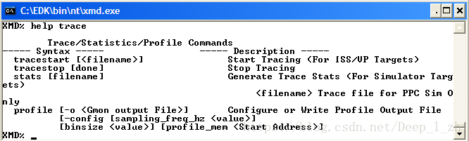
TRACESTART (Start Tracing): This command is used only for ISS/VP targets and is used to collect instruction and function trace information associated with a specific file. The syntax is shown below
XMD% tracestart [pc trace filename] [-function_name <func trace filename>]
TRACESTOP: This command indicates when to stop collecting instruction and function trace information. This is only supported by ISS/VP targets.
XMD% tracestop [done]
STATS: Displays execution statistics for the ISS/VP targets.
XMD% stats [filename]
PROFILE: Configures the profile sampling frequency, histogram bin size and memory address for collecting profile data. It also writes the profile output file.
XMD% profile [-o GMON output file] [-config [sampling frequency value (Hz)]] [binsize value] [profile memory (Start Address)]
Command type: MISC – Miscellaneous Options (help trace)
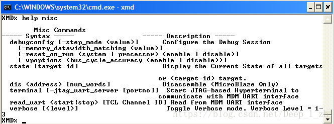
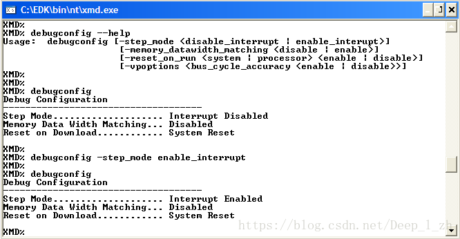
DEBUGCONFIG : The Debug session for the target is configured with this command. As shown in the above figure, it has many configuration options. The syntax is shown below. For more help type debugconfig –help
XMD% debugconfig [-step mode <step type>]
[-memory_datawidth_matching <value (disable/enable)>]
[-vpoptions <virtual platform options>] (N.A. PowerPC)
[-reset_on_run <options>]
To see the current debug configuration type debugconfig in the command line. The following figure shows some examples of the usage of this command.
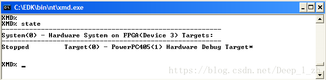
STATE: By using this command, the current state of the targets in the system is displayed. There are two possible options for this command. The syntax for the two cases is shown below.
XMD% state
XMD% state <target ID>
The following figure shows the usage of this command. Note that the target is stopped.
DIS (Disassemble): Disassemble instruction. This command is used only for the MicroBlaze processor. It will not be used when working with the PowerPC architecture.
XMD% dis [address] [num_words] (dis 0x1234 12)
TERMINAL: With this command, the communication between the JTAG-based hyperterminal and the opb_mdmUART interface is started. Since the PowerPC is used, this command will not be employed.
XMD% terminal
XMD% terminal [-jtag_uart_server [port number]]
READ_UART: By using this command followed by the word start the output of the MDM_UART is redirected to a TCL channel. When the command is followed by the word stop the redirection is stopped. Finally, the TCL channel ID could be specified as it shown in the examples below. This command will not be used.
XMD% read_uart [start | stop]
XMD% read_uart [start | stop] [TCL channel ID]
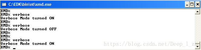
VERBOSE: Toggles verbose mode. To use this command, type verbose in the command line. When the verbose command is used, the verbose mode switches between on and off modes. In the figure, the usage of the command is shown.
XMD% verbose
XMD% verbose [level]