1.1 问题
VLAN(虚拟局域网)是对连接到的第二层交换机端口的网络用户的逻辑分段,不受网络用户的物理位置限制而根据用户需求进行网络分段。一个VLAN可以在一个交换机或者跨交换机实现。VLAN可以根据网络用户的位置、作用、部门或者根据网络用户所使用的应用程序和协议来进行分组。基于交换机的虚拟局域网能够为局域网解决冲突域、广播域、带宽问题。
- 按企业部门规划vlan
1.2 方案
在交换机上创建vlan2、vlan3,参照如下网络拓扑如图-1所示:
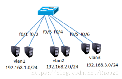
图-1
1.3 步骤
实现此案例需要按照如下步骤进行。
步骤一:客户端与交换机相连
1)为了使同vlan在交换机上可以通信,需要给同vlan客户端配置同网段IP地址,如图-2、图-3所示
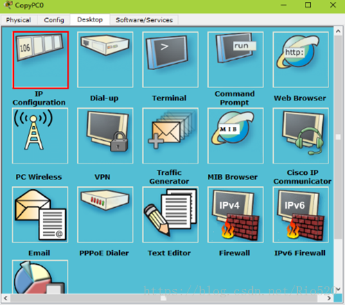
图-2
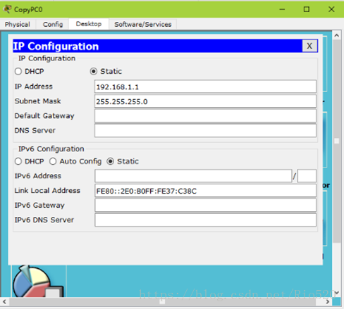
图-3
分别配置为192.168.1.1、192.169.1.2;192.168.2.1、192.168.2.2;192.168.3.1、192.168.3.2;
2)在交换机上创建vlan2 和vlan3并将指定的接口划分到相对应的vlan下
- Switch >enable
- Switch#configure terminal
- Switch(config)#vlan 2
- Switch(config-vlan)#exit
- Switch(config)#vlan 3
- Switch(config-vlan)#exit
- Switch(config)#interface fastEthernet 0/3
- Switch(config-if)#switchport access vlan 2
- Switch(config-if)#exit
- Switch(config)#interface fastEthernet 0/4
- Switch(config-if)#switchport access vlan 2
- Switch(config-if)#exit
- Switch(config)#interface fastEthernet 0/5
- Switch(config-if)#switchport access vlan 3
- Switch(config-if)#exit
- Switch(config)#interface fastEthernet 0/6
- Switch(config-if)#switchport access vlan 3
Switch >enable
Switch#configure terminal
Switch(config)#vlan 2
Switch(config-vlan)#exit
Switch(config)#vlan 3
Switch(config-vlan)#exit
Switch(config)#interface fastEthernet 0/3
Switch(config-if)#switchport access vlan 2
Switch(config-if)#exit
Switch(config)#interface fastEthernet 0/4
Switch(config-if)#switchport access vlan 2
Switch(config-if)#exit
Switch(config)#interface fastEthernet 0/5
Switch(config-if)#switchport access vlan 3
Switch(config-if)#exit
Switch(config)#interface fastEthernet 0/6
Switch(config-if)#switchport access vlan 3
3)在交换机上查看vlan信息,可以看到创建的vlan以及vlan下的接口
- Switch>enable
- Switch#show vlan
- VLAN Name Status Ports
- ----------------------------------------------------------------------------
- 1defaultactive Fa0/1, Fa0/2, Fa0/7, Fa0/8
- Fa0/9,Fa0/10,Fa0/11,Fa0/12
- Fa0/13,Fa0/14,Fa0/15,Fa0/16
- Fa0/17,Fa0/18,Fa0/19,Fa0/20
- Fa0/21,Fa0/22,Fa0/23,Fa0/24
- 2VLAN0002 active Fa0/3, Fa0/4
- 3VLAN0003 active Fa0/5, Fa0/6
- 1002fddi-default act/unsup
- 1003token-ring-default act/unsup
- 1004fddinet-default act/unsup
- 1005trnet-default act/unsup
- VLAN Type SAID MTU Parent RingNo BridgeNo Stp BrdgMode Trans1 Trans2
- --------------------------------------------------------------------
- 1enet 100001 1500 - - - - - 0 0
- 2enet 100002 1500 - - - - - 0 0
- 3enet 100003 1500 - - - - - 0 0
- 1002fddi 101002 1500 - - - - - 0 0
- 1003tr 101003 1500 - - - - - 0 0
- 1004fdnet 101004 1500 - - - ieee - 0 0
- 1005trnet 101005 1500 - - - ibm - 0 0
- Remote SPAN VLANs
- ------------------------------------------------------------------------------
- Primary Secondary Type Ports
- ---------------------------------------------------------------------------
Switch>enable
Switch#show vlan
VLAN Name Status Ports
---- -------------------------------- --------- -------------------------------
1 default active Fa0/1, Fa0/2, Fa0/7, Fa0/8
Fa0/9, Fa0/10, Fa0/11, Fa0/12
Fa0/13, Fa0/14, Fa0/15, Fa0/16
Fa0/17, Fa0/18, Fa0/19, Fa0/20
Fa0/21, Fa0/22, Fa0/23, Fa0/24
2 VLAN0002 active Fa0/3, Fa0/4
3 VLAN0003 active Fa0/5, Fa0/6
1002 fddi-default act/unsup
1003 token-ring-default act/unsup
1004 fddinet-default act/unsup
1005 trnet-default act/unsup
VLAN Type SAID MTU Parent RingNo BridgeNo Stp BrdgMode Trans1 Trans2
---- ----- ---------- ----- ------ ------ -------- ---- -------- ------ ------
1 enet 100001 1500 - - - - - 0 0
2 enet 100002 1500 - - - - - 0 0
3 enet 100003 1500 - - - - - 0 0
1002 fddi 101002 1500 - - - - - 0 0
1003 tr 101003 1500 - - - - - 0 0
1004 fdnet 101004 1500 - - - ieee - 0 0
1005 trnet 101005 1500 - - - ibm - 0 0
Remote SPAN VLANs
------------------------------------------------------------------------------
Primary Secondary Type Ports
------- --------- ----------------- ------------------------------------------
4)在客户端测试网络的连通性
在192.168.1.0/24的客户机上测试1.0网段的连通性
- PC1>ping 192.168.1.2
- Pinging 192.168.1.2 with 32 bytes of data:
- Reply from 192.168.1.2: bytes=32 time=11ms TTL=128
- Reply from 192.168.1.2: bytes=32 time=1ms TTL=128
- Reply from 192.168.1.2: bytes=32 time=1ms TTL=128
- Reply from 192.168.1.2: bytes=32 time=4ms TTL=128
- Ping statistics for 192.168.1.2:
- Packets: Sent = 4, Received = 4, Lost = 0 (0% loss),
- Approximate round trip times in milli-seconds:
- Minimum = 1ms, Maximum = 11ms, Average = 4ms
PC1>ping 192.168.1.2
Pinging 192.168.1.2 with 32 bytes of data:
Reply from 192.168.1.2: bytes=32 time=11ms TTL=128
Reply from 192.168.1.2: bytes=32 time=1ms TTL=128
Reply from 192.168.1.2: bytes=32 time=1ms TTL=128
Reply from 192.168.1.2: bytes=32 time=4ms TTL=128
Ping statistics for 192.168.1.2:
Packets: Sent = 4, Received = 4, Lost = 0 (0% loss),
Approximate round trip times in milli-seconds:
Minimum = 1ms, Maximum = 11ms, Average = 4ms
5)在192.168.2.0/24的客户机上测试2.0网段的连通性
- PC>ping 192.168.2.2
- Pinging 192.168.2.2 with 32 bytes of data:
- Reply from 192.168.2.2: bytes=32 time=1ms TTL=128
- Reply from 192.168.2.2: bytes=32 time=0ms TTL=128
- Reply from 192.168.2.2: bytes=32 time=0ms TTL=128
- Reply from 192.168.2.2: bytes=32 time=0ms TTL=128
- Ping statistics for 192.168.2.2:
- Packets: Sent = 4, Received = 4, Lost = 0 (0% loss),
- Approximate round trip times in milli-seconds:
- Minimum = 0ms, Maximum = 1ms, Average = 0ms
PC>ping 192.168.2.2
Pinging 192.168.2.2 with 32 bytes of data:
Reply from 192.168.2.2: bytes=32 time=1ms TTL=128
Reply from 192.168.2.2: bytes=32 time=0ms TTL=128
Reply from 192.168.2.2: bytes=32 time=0ms TTL=128
Reply from 192.168.2.2: bytes=32 time=0ms TTL=128
Ping statistics for 192.168.2.2:
Packets: Sent = 4, Received = 4, Lost = 0 (0% loss),
Approximate round trip times in milli-seconds:
Minimum = 0ms, Maximum = 1ms, Average = 0ms
6)在192.168.3.0/24的客户机上测试3.0网段的连通性
- PC>ping 192.168.3.2
- Pinging 192.168.3.2 with 32 bytes of data:
- Reply from 192.168.3.2: bytes=32 time=1ms TTL=128
- Reply from 192.168.3.2: bytes=32 time=0ms TTL=128
- Reply from 192.168.3.2: bytes=32 time=0ms TTL=128
- Reply from 192.168.3.2: bytes=32 time=1ms TTL=128
- Ping statistics for 192.168.3.2:
- Packets: Sent = 4, Received = 4, Lost = 0 (0% loss),
- Approximate round trip times in milli-seconds:
- Minimum = 0ms, Maximum = 1ms, Average = 0ms
PC>ping 192.168.3.2
Pinging 192.168.3.2 with 32 bytes of data:
Reply from 192.168.3.2: bytes=32 time=1ms TTL=128
Reply from 192.168.3.2: bytes=32 time=0ms TTL=128
Reply from 192.168.3.2: bytes=32 time=0ms TTL=128
Reply from 192.168.3.2: bytes=32 time=1ms TTL=128
Ping statistics for 192.168.3.2:
Packets: Sent = 4, Received = 4, Lost = 0 (0% loss),
Approximate round trip times in milli-seconds:
Minimum = 0ms, Maximum = 1ms, Average = 0ms
2.1 问题
在两台交换机上分别创建vlan2、vlan3,参照如下网络拓扑图-4将端口加入到指定的vlan并配置IP址,实现跨交换机的同vlan主机的通信。
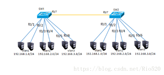
图-4
2.2 方案
分别在sw1和sw2上创建vlan2和vlan3并把相应的接口划分到对应的vlan并为客户端配置IP地址,IP地址具有唯一性所以同一局域网络中不能存在相同的IP,另所有的接口默认为vlan1,所以不配置trunk中继链路vlan1也是可以跨交换机通信的。
2.3 步骤
实现此案例需要按照如下步骤进行
步骤一:为客户端配置IP,分别为交换机sw1和sw2创建vlan并把相应的接口划到相对应的vlan下
1)参照图-4为客户端分别配置相对应网段的IP
2)为交换机创建vlan2、vlan3 并把相应的接口划到vlan下
- Switch >enable
- Switch#configure terminal
- Switch(config)#hostname SW1
- SW1(config)#Switch(config-vlan)#exit
- SW1(config)#vlan 3
- SW1(config-vlan)#exit
- SW1(config)#interface fastEthernet 0/3
- SW1(config-if)#switchport access vlan 2
- SW1(config-if)#exit
- SW1(config)#interface fastEthernet 0/4
- SW1(config-if)#switchport access vlan 2
- SW1(config-if)#exit
- SW1(config)#interface fastEthernet 0/5
- SW1(config-if)#switchport access vlan 3
- SW1(config-if)#exit
- SW1(config)#interface fastEthernet 0/6
- SW1(config-if)#switchport access vlan 3
- Switch >enable
- Switch#configure terminal
- Enter configuration commands, one per line. End with CNTL/Z.
- Switch(config)#hostname SW2
- SW2(config)#Switch(config-vlan)#exit
- SW2(config)#vlan 3
- SW2(config-vlan)#exit
- SW2(config)#interface fastEthernet 0/3
- SW2(config-if)#switchport access vlan 2
- SW2(config-if)#exit
- SW2(config)#interface fastEthernet 0/4
- SW2(config-if)#switchport access vlan 2
- SW2(config-if)#exit
- SW2(config)#interface fastEthernet 0/5
- SW2(config-if)#switchport access vlan 3
- SW2(config-if)#exit
- SW2(config)#interface fastEthernet 0/6
- SW2(config-if)#switchport access vlan 3
Switch >enable
Switch#configure terminal
Switch(config)#hostname SW1
SW1 (config)#Switch(config-vlan)#exit
SW1 (config)#vlan 3
SW1 (config-vlan)#exit
SW1 (config)#interface fastEthernet 0/3
SW1 (config-if)#switchport access vlan 2
SW1 (config-if)#exit
SW1 (config)#interface fastEthernet 0/4
SW1 (config-if)#switchport access vlan 2
SW1 (config-if)#exit
SW1 (config)#interface fastEthernet 0/5
SW1 (config-if)#switchport access vlan 3
SW1 (config-if)#exit
SW1 (config)#interface fastEthernet 0/6
SW1 (config-if)#switchport access vlan 3
Switch >enable
Switch#configure terminal
Enter configuration commands, one per line. End with CNTL/Z.
Switch(config)#hostname SW2
SW2 (config)#Switch(config-vlan)#exit
SW2 (config)#vlan 3
SW2 (config-vlan)#exit
SW2 (config)#interface fastEthernet 0/3
SW2(config-if)#switchport access vlan 2
SW2 (config-if)#exit
SW2 (config)#interface fastEthernet 0/4
SW2 (config-if)#switchport access vlan 2
SW2 (config-if)#exit
SW2 (config)#interface fastEthernet 0/5
SW2 (config-if)#switchport access vlan 3
SW2 (config-if)#exit
SW2 (config)#interface fastEthernet 0/6
SW2 (config-if)#switchport access vlan 3
3)分别查看SW1和SW2交换机上的vlan信息
- SW1#show vlan
- VLAN Name Status Ports
- ----------------------------------------------------------------------------
- 1defaultactive Fa0/1, Fa0/2, Fa0/8, Fa0/9
- Fa0/10,Fa0/11,Fa0/12,Fa0/13
- Fa0/14,Fa0/15,Fa0/16,Fa0/17
- Fa0/18,Fa0/19,Fa0/20,Fa0/21
- Fa0/22,Fa0/23,Fa0/24
- 2VLAN0002 active Fa0/3, Fa0/4
- 3VLAN0003 active Fa0/5, Fa0/6
- 1002fddi-default act/unsup
- 1003token-ring-default act/unsup
- 1004fddinet-default act/unsup
- 1005trnet-default act/unsup
- VLAN Type SAID MTU Parent RingNo BridgeNo Stp BrdgMode Trans1 Trans2
- --------------------------------------------------------------------
- 1enet 100001 1500 - - - - - 0 0
- 2enet 100002 1500 - - - - - 0 0
- 3enet 100003 1500 - - - - - 0 0
- 1002fddi 101002 1500 - - - - - 0 0
- 1003tr 101003 1500 - - - - - 0 0
- 1004fdnet 101004 1500 - - - ieee - 0 0
- 1005trnet 101005 1500 - - - ibm - 0 0
- Remote SPAN VLANs
- ------------------------------------------------------------------------------
- Primary Secondary Type Ports
- ---------------------------------------------------------------------------
- SW1#
- SW2#show vlan
- VLAN Name Status Ports
- ----------------------------------------------------------------------------
- 1defaultactive Fa0/1, Fa0/2, Fa0/8, Fa0/9
- Fa0/10,Fa0/11,Fa0/12,Fa0/13
- Fa0/14,Fa0/15,Fa0/16,Fa0/17
- Fa0/18,Fa0/19,Fa0/20,Fa0/21
- Fa0/22,Fa0/23,Fa0/24
- 2VLAN0002 active Fa0/3, Fa0/4
- 3VLAN0003 active Fa0/5, Fa0/6
- 1002fddi-default act/unsup
- 1003token-ring-default act/unsup
- 1004fddinet-default act/unsup
- 1005trnet-default act/unsup
- VLAN Type SAID MTU Parent RingNo BridgeNo Stp BrdgMode Trans1 Trans2
- --------------------------------------------------------------------
- 1enet 100001 1500 - - - - - 0 0
- 2enet 100002 1500 - - - - - 0 0
- 3enet 100003 1500 - - - - - 0 0
- 1002fddi 101002 1500 - - - - - 0 0
- 1003tr 101003 1500 - - - - - 0 0
- 1004fdnet 101004 1500 - - - ieee - 0 0
- 1005trnet 101005 1500 - - - ibm - 0 0
- Remote SPAN VLANs
- ------------------------------------------------------------------------------
- Primary Secondary Type Ports
- ---------------------------------------------------------------------------
- SW2#
SW1#show vlan
VLAN Name Status Ports
---- -------------------------------- --------- -------------------------------
1 default active Fa0/1, Fa0/2, Fa0/8, Fa0/9
Fa0/10, Fa0/11, Fa0/12, Fa0/13
Fa0/14, Fa0/15, Fa0/16, Fa0/17
Fa0/18, Fa0/19, Fa0/20, Fa0/21
Fa0/22, Fa0/23, Fa0/24
2 VLAN0002 active Fa0/3, Fa0/4
3 VLAN0003 active Fa0/5, Fa0/6
1002 fddi-default act/unsup
1003 token-ring-default act/unsup
1004 fddinet-default act/unsup
1005 trnet-default act/unsup
VLAN Type SAID MTU Parent RingNo BridgeNo Stp BrdgMode Trans1 Trans2
---- ----- ---------- ----- ------ ------ -------- ---- -------- ------ ------
1 enet 100001 1500 - - - - - 0 0
2 enet 100002 1500 - - - - - 0 0
3 enet 100003 1500 - - - - - 0 0
1002 fddi 101002 1500 - - - - - 0 0
1003 tr 101003 1500 - - - - - 0 0
1004 fdnet 101004 1500 - - - ieee - 0 0
1005 trnet 101005 1500 - - - ibm - 0 0
Remote SPAN VLANs
------------------------------------------------------------------------------
Primary Secondary Type Ports
------- --------- ----------------- ------------------------------------------
SW1#
SW2#show vlan
VLAN Name Status Ports
---- -------------------------------- --------- -------------------------------
1 default active Fa0/1, Fa0/2, Fa0/8, Fa0/9
Fa0/10, Fa0/11, Fa0/12, Fa0/13
Fa0/14, Fa0/15, Fa0/16, Fa0/17
Fa0/18, Fa0/19, Fa0/20, Fa0/21
Fa0/22, Fa0/23, Fa0/24
2 VLAN0002 active Fa0/3, Fa0/4
3 VLAN0003 active Fa0/5, Fa0/6
1002 fddi-default act/unsup
1003 token-ring-default act/unsup
1004 fddinet-default act/unsup
1005 trnet-default act/unsup
VLAN Type SAID MTU Parent RingNo BridgeNo Stp BrdgMode Trans1 Trans2
---- ----- ---------- ----- ------ ------ -------- ---- -------- ------ ------
1 enet 100001 1500 - - - - - 0 0
2 enet 100002 1500 - - - - - 0 0
3 enet 100003 1500 - - - - - 0 0
1002 fddi 101002 1500 - - - - - 0 0
1003 tr 101003 1500 - - - - - 0 0
1004 fdnet 101004 1500 - - - ieee - 0 0
1005 trnet 101005 1500 - - - ibm - 0 0
Remote SPAN VLANs
------------------------------------------------------------------------------
Primary Secondary Type Ports
------- --------- ----------------- ------------------------------------------
SW2#
步骤二:为交换机配置trunk中继链接路
1)分别进入两台交换机相连接的f0/7接口配置trunk中继链路
- SW1>enable
- SW1#configure terminal
- SW1(config)#interface fastEthernet 0/7
- SW1(config-if)#switchport mode trunk
- SW2#enable
- SW2#configure terminal
- SW2(config)#interface fastEthernet 0/7
- SW2(config-if)#switchport mode trunk
- SW2(config-if)#
SW1>enable
SW1#configure terminal
SW1(config)#interface fastEthernet 0/7
SW1(config-if)#switchport mode trunk
SW2#enable
SW2#configure terminal
SW2(config)#interface fastEthernet 0/7
SW2(config-if)#switchport mode trunk
SW2(config-if)#
2)测试2.0网段和3.0网段跨交换机通信
- PC>ping 192.168.2.3
- Pinging 192.168.2.3 with 32 bytes of data:
- Reply from 192.168.2.3: bytes=32 time=1ms TTL=128
- Reply from 192.168.2.3: bytes=32 time=0ms TTL=128
- Reply from 192.168.2.3: bytes=32 time=0ms TTL=128
- Reply from 192.168.2.3: bytes=32 time=0ms TTL=128
- Ping statistics for 192.168.2.3:
- Packets: Sent = 4, Received = 4, Lost = 0 (0% loss),
- Approximate round trip times in milli-seconds:
- Minimum = 0ms, Maximum = 1ms, Average = 0ms
- PC>ping 192.168.3.3
- Pinging 192.168.3.3 with 32 bytes of data:
- Reply from 192.168.3.3: bytes=32 time=1ms TTL=128
- Reply from 192.168.3.3: bytes=32 time=0ms TTL=128
- Reply from 192.168.3.3: bytes=32 time=0ms TTL=128
- Reply from 192.168.3.3: bytes=32 time=0ms TTL=128
- Ping statistics for 192.168.3.3:
- Packets: Sent = 4, Received = 4, Lost = 0 (0% loss),
- Approximate round trip times in milli-seconds:
- Minimum = 0ms, Maximum = 1ms, Average = 0ms
PC>ping 192.168.2.3
Pinging 192.168.2.3 with 32 bytes of data:
Reply from 192.168.2.3: bytes=32 time=1ms TTL=128
Reply from 192.168.2.3: bytes=32 time=0ms TTL=128
Reply from 192.168.2.3: bytes=32 time=0ms TTL=128
Reply from 192.168.2.3: bytes=32 time=0ms TTL=128
Ping statistics for 192.168.2.3:
Packets: Sent = 4, Received = 4, Lost = 0 (0% loss),
Approximate round trip times in milli-seconds:
Minimum = 0ms, Maximum = 1ms, Average = 0ms
PC>ping 192.168.3.3
Pinging 192.168.3.3 with 32 bytes of data:
Reply from 192.168.3.3: bytes=32 time=1ms TTL=128
Reply from 192.168.3.3: bytes=32 time=0ms TTL=128
Reply from 192.168.3.3: bytes=32 time=0ms TTL=128
Reply from 192.168.3.3: bytes=32 time=0ms TTL=128
Ping statistics for 192.168.3.3:
Packets: Sent = 4, Received = 4, Lost = 0 (0% loss),
Approximate round trip times in milli-seconds:
Minimum = 0ms, Maximum = 1ms, Average = 0ms
3.1 问题
企业需要增加带宽和网络可用性,以太通道可以同时满足这两个条件,而又无需购买新设备。
3.2 方案
在某些环境下,为了在现有条件下增加带宽而不增加额外的设备,以太通道是可用技术之一。以太通道为交换机提供了端口捆绑的技术,允许两个交换机之间通过两个或多个端口并行连接,同时传输数据,以提供更高的带宽。
企业网络模拟拓扑环境如图-5所示:
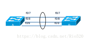
图-5
3.3 步骤
实现此案例需要按照如下步骤进行。
步骤一:在交换机A上分别配置以太通道
太通道的配置模式与Trunk类似,也有开启、企望等。同样的,在生产环境下都是强制设置以太通道处于on的状态,而不是让它们自动协商。
- sw1(config)# interface range fastEthernet 0/7 – 9
- Switch(config-if-range)#switchport mode trunk
- sw1(config-if-range)#channel-group 1 mode on
- sw1(config-if-range)#
sw1(config)# interface range fastEthernet 0/7 – 9
Switch(config-if-range)#switchport mode trunk
sw1(config-if-range)#channel-group 1 mode on
sw1(config-if-range)#
步骤二:在交换机B上分别配置以太通道
- sw2(config)# interface range fastEthernet 0/7 – 9
- Switch(config-if-range)#switchport mode trunk
- sw2(config-if-range)#channel-group 1 mode on
- sw2(config-if-range)#
sw2(config)# interface range fastEthernet 0/7 – 9
Switch(config-if-range)#switchport mode trunk
sw2(config-if-range)#channel-group 1 mode on
sw2(config-if-range)#
步骤三:在交换机A上查看以太通通道配置
- sw1# show etherchannel 1 summary
- Flags: D - down P - in port-channel
- I - stand-alone s - suspended
- H - Hot-standby (LACP only)
- R - Layer3 S - Layer2
- U - in use f - failed to allocate aggregator
- u - unsuitable for bundling
- w - waiting to be aggregated
- d - default port
- Numberof channel-groups in use: 1
- Numberof aggregators: 1
- Group Port-channel Protocol Ports
- ------+-------------+-----------+---------------------------------
- 1Po1(SU) - Fa0/7(P) Fa0/8(P) Fa0/9(P)
sw1# show etherchannel 1 summary
Flags: D - down P - in port-channel
I - stand-alone s - suspended
H - Hot-standby (LACP only)
R - Layer3 S - Layer2
U - in use f - failed to allocate aggregator
u - unsuitable for bundling
w - waiting to be aggregated
d - default port
Number of channel-groups in use: 1
Number of aggregators: 1
Group Port-channel Protocol Ports
------+-------------+-----------+---------------------------------
1 Po1(SU) - Fa0/7(P) Fa0/8(P) Fa0/9(P)
根据输出最后一行小括号中的提示,可以获知以太通道是二层的(S)、正在被使用的(U),端口Fa0/7、Fa0/8和Fa09在以太通道中(P)。
步骤四:创建以太通道后,系统会增加一个名称为Port-channel 1的端口,可以通过show running-config命令查看到其信息
- sw2#show running-config
- Building configuration...
- Current configuration : 1308 bytes
- !
- version 12.2
- no service timestamps log datetime msec
- no service timestamps debug datetime msec
- no service password-encryption
- !
- hostname tarena-sw2
- !
- !
- ....
- interfacePort-channel 1 //以太通道信息
- switchport mode trunk
- !
- ....
sw2#show running-config
Building configuration...
Current configuration : 1308 bytes
!
version 12.2
no service timestamps log datetime msec
no service timestamps debug datetime msec
no service password-encryption
!
hostname tarena-sw2
!
!
.. ..
interface Port-channel 1 //以太通道信息
switchport mode trunk
!
.. ..
4.1 问题
大型企业网络客户机数量较多,客记机IP地址配置如果都为静态配置存在如下问题:
- 增加网络管理员工作量
- 静态手动配置容易输入错误
- 静态手动配置容易冲突
4.2 方案
在路由器上配置DHCP服务为客户端自动分配IP地址如图-6所示:
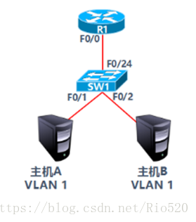
图-6
- VLAN 1:192.168.1.0/24
- 网关192.168.1.254
- 首选DNS为202.106.0.20
- 预留IP地址打印服务器:192.168.1.1
- 预留IP地址文件服务器:192.168.1.100
4.3 步骤
实现此案例需要按照如下步骤进行。
步骤一:路由器R1配置DHCP服务
1)配置路由器接口IP
- R1(config)#interface fastEthernet 0/0
- R1(config-if)#ip address 192.168.1.254 255.255.255.0
- R1(config-if)#no shutdown
R1(config)#interface fastEthernet 0/0
R1(config-if)#ip address 192.168.1.254 255.255.255.0
R1(config-if)#no shutdown
2)DHCP服务配置
- R1(config)#ip dhcp pool vlan11)
- R1(dhcp-config)#network 192.168.1.0 255.255.255.0
- R1(dhcp-config)#default-router 192.168.1.254
- R1(dhcp-config)#dns-server 202.106.0.20
- R1(config)#ip dhcp excluded-address 192.168.1.1
- R1(config)#ip dhcp excluded-address 192.168.1.100
R1(config)#ip dhcp pool vlan11)
R1(dhcp-config)#network 192.168.1.0 255.255.255.0
R1(dhcp-config)#default-router 192.168.1.254
R1(dhcp-config)#dns-server 202.106.0.20
R1(config)#ip dhcp excluded-address 192.168.1.1
R1(config)#ip dhcp excluded-address 192.168.1.100
3)设置主机A的IP配置为自动获取如图-7所示:
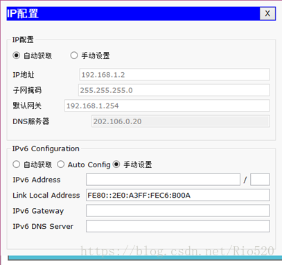
图-7