功能安全ISO26262安全管理生命周期框架如下:
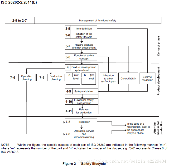
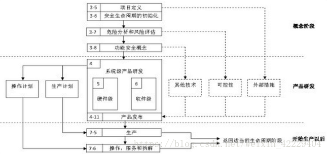
a) The subphase: item definition
The initiating task of the safety lifecycle is to develop a description of the item with regard to its
functionality, interfaces, environmental conditions, legal requirements, known hazards, etc. The boundary
of the item and its interfaces, as well as assumptions concerning other items, elements, systems and
components are determined (see ISO 26262-3:2011, Clause 5).
b) The subphase: initiation of the safety lifecycle
Based on the item definition, the safety lifecycle is initiated by distinguishing between either a new
development, or a modification of an existing item.
If an existing item is modified, the results of an impact analysis are used to tailor the safety lifecycle (see
ISO 26262-3:2011, Clause 6).
c) The subphase: hazard analysis and risk assessment
After the initiation of the safety lifecycle, the hazard analysis and risk assessment is performed as given in
ISO 26262-3:2011, Clause 7. First, the hazard analysis and risk assessment estimates the probability of
exposure, the controllability and the severity of the hazardous events with regard to the item. Together,
these parameters determine the ASILs of the hazardous events. Subsequently, the hazard analysis and
risk assessment determines the safety goals for the item, with the safety goals being the top level safety
requirements for the item. The ASILs determined for the hazardous events are assigned to the
corresponding safety goals.
During the subsequent phases and subphases, detailed safety requirements are derived from the safety
goals. These safety requirements inherit the ASIL of the corresponding safety goals.
d) The subphase: functional safety concept
Based on the safety goals, a functional safety concept (see ISO 26262-3:2011, Clause 8) is specified
considering preliminary architectural assumptions. The functional safety concept is specified by functional
safety requirements that are allocated to the elements of the item. The functional safety concept can also
include other technologies or interfaces with external measures, provided that the expected behaviours
thereof can be validated (see ISO 26262-4:2011, Clause 9). The implementation of other technologies is
outside the scope of ISO 26262 and the implementation of the external measures is outside the scope of
the item development.
e) The phase: product development at the system level
After having specified the functional safety concept, the item is developed from the system level
perspective, as given in ISO 26262-4. The system development process is based on the concept of a
V-model with the specification of the technical safety requirements, the system architecture, the system
design and implementation on the left hand branch and the integration, verification, validation and the
functional safety assessment on the right hand branch.
The hardware-software interface is specified in this phase.
Figure 1 provides an overview of the subphases of the product development at the system level.
The product development at the system level incorporates validation tasks for activities occurring within
other safety lifecycle phases, including
the validation of the aspects of the functional safety concept that are implemented by other
technologies;
ISO 26262-2:2011(E)
6 © ISO 2011 – All rights reserved
the validation of the assumptions concerning the effectiveness and the performance of external
measures; and
the validation of the assumptions concerning human response, including controllability and
operational tasks.
The release for production is the final subphase of the product development and provides the item’s
release for series production (see ISO 26262-4:2011, Clause 11).
f) The phase: product development at the hardware level
Based on the system design specification, the item is developed from the hardware level perspective (see
ISO 26262-5). The hardware development process is based on the concept of a V-model with the
specification of the hardware requirements and the hardware design and implementation on the left hand
branch and the hardware integration and testing on the right hand branch.
Figure 1 provides an overview of the subphases of the product development at the hardware level.
g) The phase: product development at the software level
Based on the system design specification, the item is developed from the software level perspective (see
ISO 26262-6). The software development process is based on the concept of a V-model with the
specification of the software requirements and the software architectural design and implementation on
the left hand branch, and the software integration and testing, and the verification of the software
requirements on the right hand branch.
Figure 1 provides an overview of the subphases of the product development at the software level.
h) Production planning and operation planning
The planning for production and operation, and the specification of the associated requirements, starts
during the product development at the system level (see ISO 26262-4). The requirements for production
and operation are given in ISO 26262-7:2011, Clauses 5 and 6.
i) The phase: production and operation, service and decommissioning
This phase addresses the production processes relevant for the functional safety goals of the item, i.e.
the safety-related special characteristics, and the development and management of instructions for the
maintenance, repair and decommissioning of the item to ensure functional safety after the item's release
for production (see ISO 26262-7:2011, Clauses 5 and 6).
j) Controllability
In the hazard analysis and risk assessment (see ISO 26262-3:2011, Clause 7), credit can be taken for the
ability of the driver, or the other persons at risk, to control hazardous situations. The assumptions
regarding the controllability in the hazard analysis and risk assessment and the functional and technical
safety concept are validated during the safety validation (see Figure 2 and ISO 26262-4:2011, Clause 9).
NOTE The exposure and the severity are factors that depend on the scenario. The eventual controllability
through human intervention is influenced by the design of the item and is therefore evaluated during the validation
(see ISO 26262-4:2011, 9.4.3.2).
k) External measures
The external measures refer to the measures outside the item, as specified in the item definition (see
Figure 2 and ISO 26262-3:2011, Clause 5), that reduce or mitigate the risks resulting from the item.
External measures can include not only additional in-vehicle devices such as dynamic stability controllers
or run-flat tyres, but also devices external to the vehicle, like crash barriers or tunnel fire-fighting systems.
ISO 26262-2:2011(E)
© ISO 2011 – All rights reserved 7
The assumptions regarding the external measures in the item definition, the hazard analysis and risk
assessment and the functional and technical safety concept are validated during the safety validation
(see Figure 2 and ISO 26262-4:2011, Clause 9).
External measures can be considered in the hazard analysis and risk assessment. However, if credit is
taken from an external measure in the hazard analysis and risk assessment, that external measure
cannot be considered as a risk reduction in the functional safety concept.
ISO 26262 also applies to those external measures that are in the scope of ISO 26262.
l) Other technologies
Other technologies, e.g. mechanical and hydraulic technologies, are those different from electrical and/or
electronic technologies that are in the scope of ISO 26262. These can be considered in the specification
of the functional safety concept (see Figure 2 and ISO 26262-3:2011, Clause 8), during the allocation of
safety requirements (see ISO 26262-3 and ISO 26262-4), or as an external measure.
NOTE If an implementation in another technology is specified as an external measure, then it can be useful to
repeat the hazard analysis and risk assessment to consider the associated risk reduction, which could potentially
result in a reduced ASIL of a corresponding safety goal.