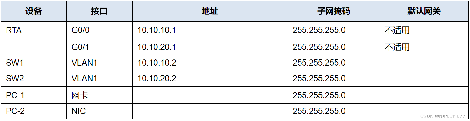
地址分配表
目标
第 1 部分:创建网络拓扑
第 2 部分:配置设备并验证连接
说明
第 1 部分:创建网络拓扑
步骤 1:获取所需的设备。
a. 单击底部工具栏中的 “ Network Devices(网络设备) ” 图标。
b. 点击子菜单中的路由器图标。
c. 找到1941路由器的图标。单击并且把 1941 路由器的图标拖动到拓扑区域中。
d. 单击子菜单中的交换机条目。
e. 找到 2960 交换机的图标。单击并且把 2960 交换机的图标拖动到拓扑区域中。
f. 重复上述步骤,让 拓扑区域中有 两个 2960 交换机。
g. 单击 “ End Device(终端设备) ” 图标。
h. 找到 PC 图标。把 两台 PC 拖到拓扑区域。
i. 通过单击并 拖动将设备排列到可以使用的布局中。
步骤 2:命名设备。
这些设备都有一个默认的名称,您需要对这个名称进行 修改。您需要按照 “地址分配表” 所示来命名设备。您 正在更改设备的显示名称。这是每个设备下方显示的文本标签。 您的显示名称必须和地址分配 表中的信息 完全匹配。如果显示名称不匹配, 您的设备配置就不会得分。
a. 单击设备图标下方的设备显示名称。文本 字段应该会显示出一个闪烁的插入点。如果设备的配置 窗口显示出来,就关闭这个窗口并重试,点击的位置要离设备图标稍 远一点。
b. 用 地址分配表中的显示名称替换掉当前的显示名称。
c. 重复这个步骤,直到所有设备都命名完成。
步骤 3:连接设备。
a. 单击底部工具栏中的橙色闪电连接图标。
b. 找到 Copper Straight-Through(铜质直通)线缆的图标。它看上去像是一个黑色对角实线 。
c. 要连接设备,单击铜质直通线缆的图标, 然后单击要连接的第一台设备。选择正确的端口 ,然后单击第二个设备。选择正确的端口,这两台设备就 会连接起来。
d. 按照下表所示来连接设备。
按照以下拓扑图设计
注意:
a.需改名

b.RTA为1941。

c.给PC-1,PC-2配置IP地址。

d.需要按照以下表格连接设备,用Copper Straight-Through连接。


第 2 部分:配置设备
在 地址分配表中记录 PC 地址和网关地址。您可以使用 PC-1 和 PC-2 网络中的任何可用地址。
步骤 1:配置路由器。
打开配置窗口
a. 配置基本设置。
1) 主机名如地址分配表中所示。
2) 把 Ciscoenpa55 配置为加密密码。
3) 把 Ciscolinepa55 配置为线路上的密码。
4) 所有线路都应该接受连接。
5) 配置当日消息 (MOTD) 标语。
Router>ENABLE
Router#conf t
Enter configuration commands, one per line.  End with CNTL/Z.
Router(config)#hostname RTA
RTA(config)#enable secret Ciscoenpa55
RTA(config)#line console 0
RTA(config-line)#password Ciscolinepa55
RTA(config-line)#login
RTA(config-line)#exit
RTA(config)#line vty 0 4
RTA(config-line)#password Ciscolinepa55
RTA(config-line)#login
RTA(config-line)#exit
RTA(config)#service password-encryption
RTA(config)#banner motd $The day banner$
RTA(config)#
b. 配置接口设置。
1) 编址信息。
2) 接口上的描述信息。
3) 保存您的配置。

RTA(config)#interface g0/0
RTA(config-if)#ip address 10.10.10.1 255.255.255.0
RTA(config-if)#description Link to SW1
RTA(config-if)#no shutdown

RTA(config-if)#
%LINK-5-CHANGED: Interface GigabitEthernet0/0, changed state to up

%LINEPROTO-5-UPDOWN: Line protocol on Interface GigabitEthernet0/0, changed state to up

RTA(config-if)#exit
RTA(config)#interface g0/1
RTA(config-if)#ip address 10.10.20.1 255.255.255.0
RTA(config-if)#description Link to SW2
RTA(config-if)#no shutdown

RTA(config-if)#
%LINK-5-CHANGED: Interface GigabitEthernet0/1, changed state to up

%LINEPROTO-5-UPDOWN: Line protocol on Interface GigabitEthernet0/1, changed state to up

RTA(config-if)#end
RTA#
%SYS-5-CONFIG_I: Configured from console by console

RTA#copy running-config startup-config
Destination filename [startup-config]?
Building configuration...
[OK]
RTA#
步骤 2:配置交换机 SW1 和 SW2。
a. 配置默认的管理接口,让它可以接受 来自本地和远程主机的网络连接。使用 地址分配表中的值。
b. 使用上面步骤 1a 中的值配置一个加密密码。
c. 使用上面步骤 1a 中的密码配置所有的线路,来接受连接。
d. 配置交换机,让它们可以将数据发送给远程 网络中的主机。
e. 保存您的配置。
SW1(精简版答案):
Switch>enable
Switch#config terminal
Switch(config)#hostname SW1

SW1(config)#enable secret Ciscoenpa55

SW1(config)#line console 0
SW1(config-line)#password Ciscolinepa55
SW1(config-line)#login
SW1(config-line)#exit

SW1(config)#line vty 0 4
SW1(config-line)#password Ciscolinepa55
SW1(config-line)#login
SW1(config-line)#exit

SW1(config)#service password-encryption

SW1(config)#interface vlan 1
SW1(config-if)#ip address 10.10.10.2 255.255.255.0
SW1(config-if)#no shutdown
SW1(config-if)#exit

SW1(config)#ip default-gateway 10.10.10.1
SW1(config)#end

SW1#copy running-config startup-config
SW2:
Switch>enable
Switch#conf t
Enter configuration commands, one per line.  End with CNTL/Z.
Switch(config)#hostname SW2
SW2(config)#enable secret Ciscoenpa55
SW2(config)#line console 0
SW2(config-line)#password Ciscolinepa55
SW2(config-line)#login
SW2(config-line)#exit
SW2(config)#line vty 0 4
SW2(config-line)#password Ciscolinepa55
SW2(config-line)#login
SW2(config-line)#exit
SW2(config)#service password-encryption
SW2(config)#interface vlan 1
SW2(config-if)#ip address 10.10.20.2 255.255.255.0
SW2(config-if)#no shutdown

SW2(config-if)#
%LINK-5-CHANGED: Interface Vlan1, changed state to up

%LINEPROTO-5-UPDOWN: Line protocol on Interface Vlan1, changed state to up

SW2(config-if)#exit
SW2(config)#ip default-gateway 10.10.20.1
SW2(config)#end
SW2#
%SYS-5-CONFIG_I: Configured from console by console

SW2#copy running-config startup-config
Destination filename [startup-config]?
Building configuration...
[OK]
SW2#
关闭配置窗口
第 3 步:配置主机。
在主机上配置 地址。如果您的配置已完成,那就应该 能够 ping 通拓扑中的所有设备。