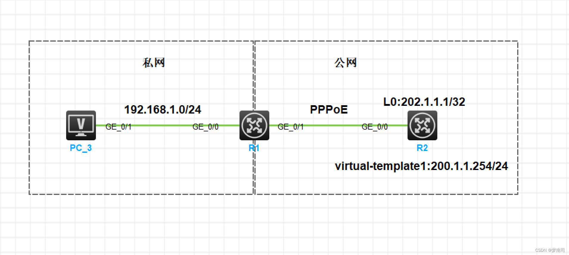
实验拓扑
注:如无特别说明,描述中的 R1 或 SW1 对应拓扑中设备名称末尾数字为 1 的设备,R2 或 SW2 对应拓扑中设备名称末尾数字为 2 的设备,以此类推;另外,同一网段中,IP 地址的主机位为其设备编号,如 R3 的 g0/0 接口若在 192.168.1.0/24 网段,则其 IP 地址为 192.168.1.3/24,以此类推
实验需求
1、如图,私网内部配置为 192.168.1.0/24 网段,R2 上配置 Loopback0 口模拟互联网地址
2、配置 R2 为 PPPoE Server,为 R1 提供 PPPoE 拨号服务,并为 R1 自动分配公网 IP 地址
3、配置 R1 为 PPPoE Client,自动进行拨号,永久在线,并能够自动获得公网 IP 地址
4、在 R1 上配置默认路由,并配置 EASY IP,使 PC3 可以访问互联网
实验解法
1、配置 IP 地址:
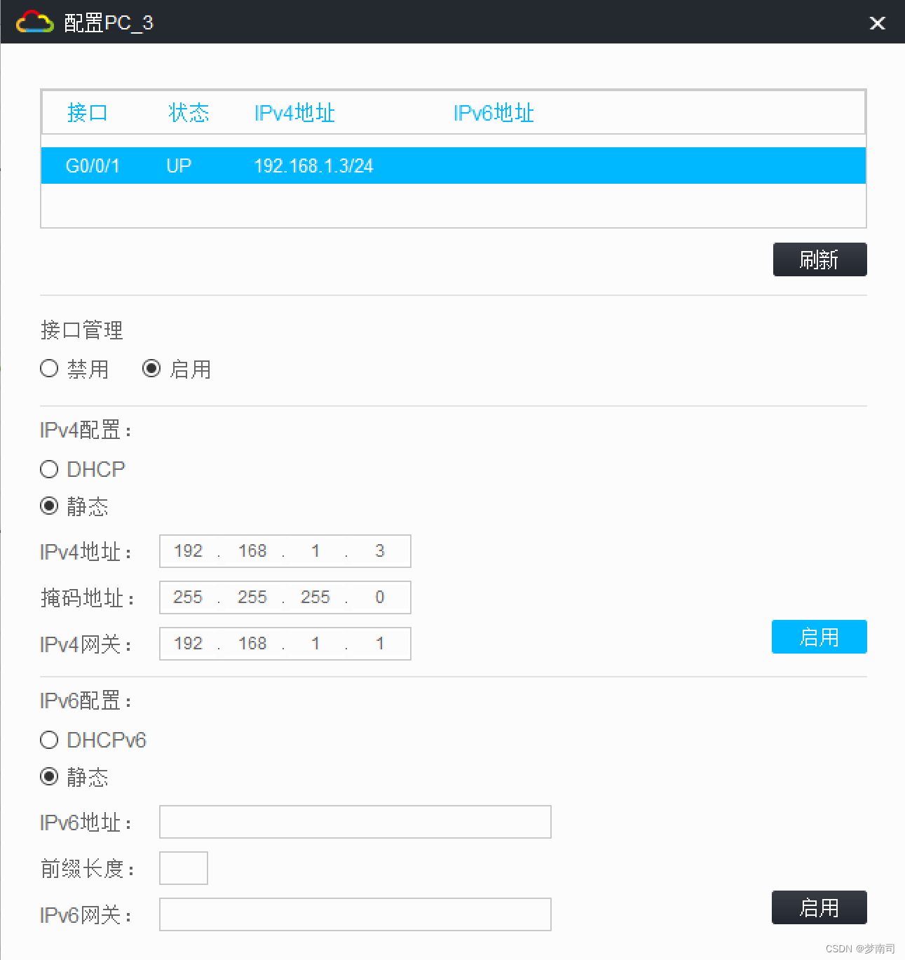
PC3:
R1:
<H3C>sys
System View: return to User View with Ctrl+Z.
[H3C]sysname R1
[R1]int g0/0
[R1-GigabitEthernet0/0]ip address 192.168.1.1 24
R2:
<R2>sys
System View: return to User View with Ctrl+Z.
[R2]int LoopBack 0
[R2-LoopBack0]ip address 202.1.1.1 32
2、配置 R2 为 PPPoE Server,为 R1 提供 PPPoE 拨号服务,并为 R1 自动分配公网 IP 地址
步骤 1:创建用户拨号验证的用户,服务类型为 PPP
[R2]local-user zhangsan class network
New local user added.
[R2-luser-network-zhangsan]password simple admin12345
[R2-luser-network-zhangsan]service-type ppp
步骤 2:创建域 h3c,配置 PPP 验证模式为本地验证
[R2]domain h3c
[R2-isp-h3c]authentication ppp local
步骤 3:创建用于动态分配给客户端的 IP 地址池
[R2]ip pool 1 200.1.1.1 200.1.1.10
步骤 4:创建 PPP 模板,配置服务端公网 IP 地址,并配置验证模式(调用域配置),绑定地址池
[R2]int Virtual-Template 1
[R2-Virtual-Template1]ppp authentication-mode chap domain h3c
[R2-Virtual-Template1]remote address pool 1
[R2-Virtual-Template1]ip address 200.1.1.254 24
步骤 4:在连接客户端的接口上绑定 PPP 模板
[R2]int g0/0
[R2-GigabitEthernet0/0]pppoe-server bind virtual-template 1
3、配置 R1 为 PPPoE Client,并能够自动获得公网 IP 地址
步骤 1:创建虚拟拨号接口,并配置验证,地址协商等相关参数
[R1]dialer-group 1 rule ip permit
[R1]int dialer 1
[R1-Dialer1]ip address ppp-negotiate
[R1-Dialer1]dialer bundle enable
[R1-Dialer1]dialer-group 1
[R1-Dialer1]ppp chap user zhangsan
[R1-Dialer1]ppp chap password simple admin12345
[R1-Dialer1]dialer timer idle 0
步骤 2:进入连接公网的接口,绑定虚拟拨号接口
[R1]int g0/1
[R1-GigabitEthernet0/1]pppoe-client dial-bundle-number 1
4、在 R1 上配置默认路由,并配置 EASY IP,使 PC3 可以访问互联网
步骤 1:在 R1 上配置默认路由,出接口指向Dialer1口
[R1]ip route-static 0.0.0.0 0 Dialer 1
步骤 2:配置 EASY IP,并在Dialer1口下发
[R1]acl basic 2000
[R1-acl-ipv4-basic-2000]rule permit source 192.168.1.0 0.0.0.255
[R1-acl-ipv4-basic-2000]qu
[R1]int dialer 1
[R1-Dialer1]nat outbound 2000
效果测试:在 R1 上检查,发现已经拨号成功,并获得了公网 IP 地址,PC3 也可以访问互联网
[R1]dis ip int br
*down: administratively down
(s): spoofing  (l): loopback
Interface           Physical Protocol IP address/Mask    VPN instance Description
Dia1                up       up       200.1.1.1/32       --           --
GE0/0               up       up       192.168.1.1/24     --           --
GE0/1               up       up       --                 --           --
GE0/2               down     down     --                 --           --
GE5/0               down     down     --                 --           --
GE5/1               down     down     --                 --           --
GE6/0               down     down     --                 --           --
GE6/1               down     down     --                 --           --
Ser1/0              down     down     --                 --           --
Ser2/0              down     down     --                 --           --
Ser3/0              down     down     --                 --           --
Ser4/0              down     down     --                 --           --
<H3C>ping 202.1.1.1
Ping 202.1.1.1 (202.1.1.1): 56 data bytes, press CTRL_C to break
56 bytes from 202.1.1.1: icmp_seq=0 ttl=255 time=0.305 ms
56 bytes from 202.1.1.1: icmp_seq=1 ttl=255 time=0.585 ms
56 bytes from 202.1.1.1: icmp_seq=2 ttl=255 time=0.807 ms
56 bytes from 202.1.1.1: icmp_seq=3 ttl=255 time=0.611 ms
56 bytes from 202.1.1.1: icmp_seq=4 ttl=255 time=0.627 ms