目录
一、 SPI协议简介
SPI(Serial Peripheral Interface)由 Motorola 开发,他并不是严格意义上的标准协议但是几乎所有的厂商都遵从这一协议,所以可以说它是一个“事实上的”协议。SPI 是同步四线制全双工的串行总线,目前速率最高可达 50MHZ,也属于主从式结构,所有的传输都是通过主机来发起的,但和 I2C 总线不一样的是,总线上只能有一个主机控制器。各个从机通过不同的片选线来进行选择,典型的连接图如图所示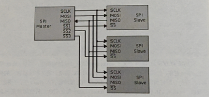
Master 是主机,有3 个片选信号SSI、SS2、SS3,分别接 3 个从机 (Slave),由片选信号来决定哪个从机被选中,从而与之通信。4 根信号线的含义如下。SCLK (Serial Clock): 串行时钟线,由主机发出。
MOSI(Master Output, Slave Input): 主出从入,即主机发数据从机接收数据的线
MISO (Master Input, Slave Output): 主入从出,即从机发数据主机接收数据的线
SS (Slave Select): 从机选择线,由主机发出,低电平有效。
因为在主机通过 MOSI 发数据的同时也可以通过 MISO 接收数据,所以 SPI 总线是全双工的。所有的数据都通过 SCLK 信号进行同步,所以它也是同步的总线。SPI 总线的典型时序图如图 所示。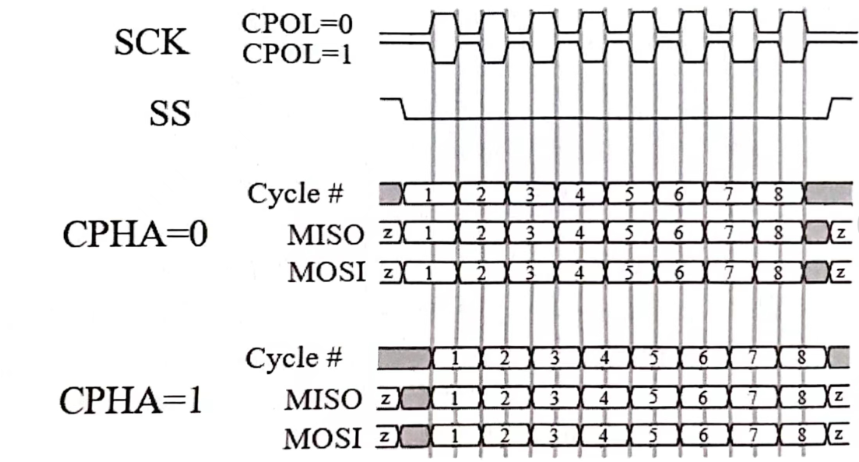
图中 CPOL 代表 SCLK 的极性,CPOL 为0表示平时 SCLK 为低电平,CPOL为1表示平时 SCLK 为高电平。CPHA 代表数据采样时的 SCLK 相位,CPHA为0表示在SCLK的前沿采样数据(可能是上升沿,也可能是下降沿),后沿输出数据:CPHA 为1表示在SCLK 的前沿输出数据,后沿采集数据。于是有下面四种组合。
CPOL=0,CPHA=0: SCLK 平时为低电平,在 SCLK 的上升沿采样 MISO 的数据在 SCLK 的下降沿从MOSI输出数据。
CPOL=0,CPHA=1:SCLK 平时为低电平,在 SCLK 的上升沿从MOSI输出数据,在 SCLK 的下降沿采样 MISO 的数据。
CPOL=1,CPHA=0: SCLK 平时为高电平,在 SCLK 的上升沿从 MOSI输出数据在 SCLK 的下降沿采样 MISO 的数据。
CPOL=1,CPHA=1:SCLK 平时为高电平,在 SCLK 的上升沿采样 MISO 的数据。在 SCLK 的下降沿从 MOSI输出数据。
如果将 CPOL 作为模式的高位,CPHA 作为模式的低位,那么上面四种模式就可以编号为 0、1、2、3,其中模式 0 和模式 3 是常用模式。
二、 Linux SPI驱动
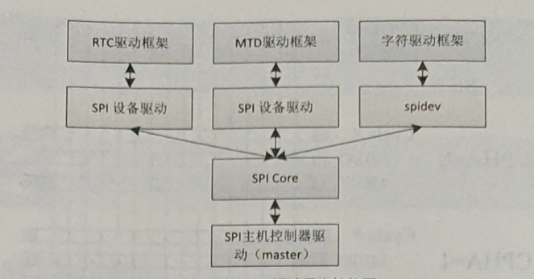
SPI驱动和 I2C 驱动非常类似,都有主机控制器驱动(称为 controller 驱动,主机控制器在驱动中叫 master)、SPI Core 和 SPI 设备驱动(称为 protocol驱动),如下图所示。使用这种结构的目的也是将主机和设备分离,因此 SPI 设备驱动不需要关心主机控制器的细节。同样的,通过 spidev 也可以将主机控制器实现为一个字符设备,使应用程序可以直接控制 SPI 主机控制器来产生时序信号,实现对 SPI 设备的访问,这个应用程序也称为应用层 SPI 设备驱动。在内核层的 SPI 设备驱动之上是其他驱动框架,用于实现特定的设备功能,如RTC、MTD 等。
SPI 的主机控制器驱动一般也是由 SoC 芯片设计厂商来实现的,我们关注更多的是SPI设备驱动。首先讲解 SPI 设备的表示方法,相应的结构类型定义如下。
struct spi_device {
    struct device dev;
    struct spi_master *master;
    u32 max_speed_hz;
    u8 chip_select;
    u8 bits_per_word;
    u16 mode;
    int irq;
    void *controller_state;
    void *controller data;
    char modalias[SPI NAME SIZE];
    int cs_gpio;
};
主要的成员含义如下。
master:所连接的SPI主机控制器。
max_speed_hz:设备工作的最高频率
chip_select: 所用的片选线。
mode:设备工作的模式。
cs_gpio: 如果用 GPIO 管脚充当片选信号,那么 cs_gpio 为 GPIO 的管脚号。
和I2C设备驱动一样,我们通常不直接构造 struct spi_device 结构对象,而是通过 struct spi_board_info 结构对象来描述 SPI设备,并用 spi register_board_info 来注册 SPI设备比如在 arch/arm/mach-s3c24xx/mach-jive.c 中就有下面的代码。
/* linux/arch/arm/mach-s3c2410/mach-jive.c
 *
 * Copyright 2007 Simtec Electronics
 *	Ben Dooks <[email protected]>
 *
 * http://armlinux.simtec.co.uk/
 *
 * This program is free software; you can redistribute it and/or modify
 * it under the terms of the GNU General Public License version 2 as
 * published by the Free Software Foundation.
*/

#include <linux/kernel.h>
#include <linux/types.h>
#include <linux/interrupt.h>
#include <linux/list.h>
#include <linux/timer.h>
#include <linux/init.h>
#include <linux/gpio.h>
#include <linux/syscore_ops.h>
#include <linux/serial_core.h>
#include <linux/platform_device.h>
#include <linux/i2c.h>

#include <video/ili9320.h>

#include <linux/spi/spi.h>
#include <linux/spi/spi_gpio.h>

#include <asm/mach/arch.h>
#include <asm/mach/map.h>
#include <asm/mach/irq.h>

#include <plat/regs-serial.h>
#include <linux/platform_data/mtd-nand-s3c2410.h>
#include <linux/platform_data/i2c-s3c2410.h>

#include <mach/regs-gpio.h>
#include <mach/regs-lcd.h>
#include <mach/fb.h>
#include <mach/gpio-samsung.h>

#include <asm/mach-types.h>

#include <linux/mtd/mtd.h>
#include <linux/mtd/nand.h>
#include <linux/mtd/nand_ecc.h>
#include <linux/mtd/partitions.h>

#include <plat/gpio-cfg.h>
#include <plat/clock.h>
#include <plat/devs.h>
#include <plat/cpu.h>
#include <plat/pm.h>
#include <linux/platform_data/usb-s3c2410_udc.h>
#include <plat/samsung-time.h>

#include "common.h"
#include "s3c2412-power.h"

static struct map_desc jive_iodesc[] __initdata = {
};

#define UCON S3C2410_UCON_DEFAULT
#define ULCON S3C2410_LCON_CS8 | S3C2410_LCON_PNONE
#define UFCON S3C2410_UFCON_RXTRIG8 | S3C2410_UFCON_FIFOMODE

static struct s3c2410_uartcfg jive_uartcfgs[] = {
	[0] = {
		.hwport	     = 0,
		.flags	     = 0,
		.ucon	     = UCON,
		.ulcon	     = ULCON,
		.ufcon	     = UFCON,
	},
	[1] = {
		.hwport	     = 1,
		.flags	     = 0,
		.ucon	     = UCON,
		.ulcon	     = ULCON,
		.ufcon	     = UFCON,
	},
	[2] = {
		.hwport	     = 2,
		.flags	     = 0,
		.ucon	     = UCON,
		.ulcon	     = ULCON,
		.ufcon	     = UFCON,
	}
};

/* Jive flash assignment
 *
 * 0x00000000-0x00028000 : uboot
 * 0x00028000-0x0002c000 : uboot env
 * 0x0002c000-0x00030000 : spare
 * 0x00030000-0x00200000 : zimage A
 * 0x00200000-0x01600000 : cramfs A
 * 0x01600000-0x017d0000 : zimage B
 * 0x017d0000-0x02bd0000 : cramfs B
 * 0x02bd0000-0x03fd0000 : yaffs
 */
static struct mtd_partition __initdata jive_imageA_nand_part[] = {

#ifdef CONFIG_MACH_JIVE_SHOW_BOOTLOADER
	/* Don't allow access to the bootloader from linux */
	{
		.name           = "uboot",
		.offset         = 0,
		.size           = (160 * SZ_1K),
		.mask_flags	= MTD_WRITEABLE, /* force read-only */
	},

	/* spare */
        {
                .name           = "spare",
                .offset         = (176 * SZ_1K),
                .size           = (16 * SZ_1K),
        },
#endif

	/* booted images */
        {
		.name		= "kernel (ro)",
		.offset		= (192 * SZ_1K),
		.size		= (SZ_2M) - (192 * SZ_1K),
		.mask_flags	= MTD_WRITEABLE, /* force read-only */
        }, {
                .name           = "root (ro)",
                .offset         = (SZ_2M),
                .size           = (20 * SZ_1M),
		.mask_flags	= MTD_WRITEABLE, /* force read-only */
        },

	/* yaffs */
	{
		.name		= "yaffs",
		.offset		= (44 * SZ_1M),
		.size		= (20 * SZ_1M),
	},

	/* bootloader environment */
	{
                .name		= "env",
		.offset		= (160 * SZ_1K),
		.size		= (16 * SZ_1K),
	},

	/* upgrade images */
        {
		.name		= "zimage",
		.offset		= (22 * SZ_1M),
		.size		= (2 * SZ_1M) - (192 * SZ_1K),
        }, {
		.name		= "cramfs",
		.offset		= (24 * SZ_1M) - (192*SZ_1K),
		.size		= (20 * SZ_1M),
        },
};

static struct mtd_partition __initdata jive_imageB_nand_part[] = {

#ifdef CONFIG_MACH_JIVE_SHOW_BOOTLOADER
	/* Don't allow access to the bootloader from linux */
	{
		.name           = "uboot",
		.offset         = 0,
		.size           = (160 * SZ_1K),
		.mask_flags	= MTD_WRITEABLE, /* force read-only */
	},

	/* spare */
        {
                .name           = "spare",
                .offset         = (176 * SZ_1K),
                .size           = (16 * SZ_1K),
        },
#endif

	/* booted images */
        {
		.name           = "kernel (ro)",
		.offset         = (22 * SZ_1M),
		.size           = (2 * SZ_1M) - (192 * SZ_1K),
		.mask_flags	= MTD_WRITEABLE, /* force read-only */
        },
	{
		.name		= "root (ro)",
		.offset		= (24 * SZ_1M) - (192 * SZ_1K),
                .size		= (20 * SZ_1M),
		.mask_flags	= MTD_WRITEABLE, /* force read-only */
	},

	/* yaffs */
	{
		.name		= "yaffs",
		.offset		= (44 * SZ_1M),
		.size		= (20 * SZ_1M),
        },

	/* bootloader environment */
	{
		.name		= "env",
		.offset		= (160 * SZ_1K),
		.size		= (16 * SZ_1K),
	},

	/* upgrade images */
	{
		.name		= "zimage",
		.offset		= (192 * SZ_1K),
		.size		= (2 * SZ_1M) - (192 * SZ_1K),
        }, {
		.name		= "cramfs",
		.offset		= (2 * SZ_1M),
		.size		= (20 * SZ_1M),
        },
};

static struct s3c2410_nand_set __initdata jive_nand_sets[] = {
	[0] = {
		.name           = "flash",
		.nr_chips       = 1,
		.nr_partitions  = ARRAY_SIZE(jive_imageA_nand_part),
		.partitions     = jive_imageA_nand_part,
	},
};

static struct s3c2410_platform_nand __initdata jive_nand_info = {
	/* set taken from osiris nand timings, possibly still conservative */
	.tacls		= 30,
	.twrph0		= 55,
	.twrph1		= 40,
	.sets		= jive_nand_sets,
	.nr_sets	= ARRAY_SIZE(jive_nand_sets),
};

static int __init jive_mtdset(char *options)
{
	struct s3c2410_nand_set *nand = &jive_nand_sets[0];
	unsigned long set;

	if (options == NULL || options[0] == '\0')
		return 0;

	if (strict_strtoul(options, 10, &set)) {
		printk(KERN_ERR "failed to parse mtdset=%s\n", options);
		return 0;
	}

	switch (set) {
	case 1:
		nand->nr_partitions = ARRAY_SIZE(jive_imageB_nand_part);
		nand->partitions = jive_imageB_nand_part;
	case 0:
		/* this is already setup in the nand info */
		break;
	default:
		printk(KERN_ERR "Unknown mtd set %ld specified,"
		       "using default.", set);
	}

	return 0;
}

/* parse the mtdset= option given to the kernel command line */
__setup("mtdset=", jive_mtdset);

/* LCD timing and setup */

#define LCD_XRES	 (240)
#define LCD_YRES	 (320)
#define LCD_LEFT_MARGIN  (12)
#define LCD_RIGHT_MARGIN (12)
#define LCD_LOWER_MARGIN (12)
#define LCD_UPPER_MARGIN (12)
#define LCD_VSYNC	 (2)
#define LCD_HSYNC	 (2)

#define LCD_REFRESH	 (60)

#define LCD_HTOT (LCD_HSYNC + LCD_LEFT_MARGIN + LCD_XRES + LCD_RIGHT_MARGIN)
#define LCD_VTOT (LCD_VSYNC + LCD_LOWER_MARGIN + LCD_YRES + LCD_UPPER_MARGIN)

static struct s3c2410fb_display jive_vgg2432a4_display[] = {
	[0] = {
		.width		= LCD_XRES,
		.height		= LCD_YRES,
		.xres		= LCD_XRES,
		.yres		= LCD_YRES,
		.left_margin	= LCD_LEFT_MARGIN,
		.right_margin	= LCD_RIGHT_MARGIN,
		.upper_margin	= LCD_UPPER_MARGIN,
		.lower_margin	= LCD_LOWER_MARGIN,
		.hsync_len	= LCD_HSYNC,
		.vsync_len	= LCD_VSYNC,

		.pixclock	= (1000000000000LL /
				   (LCD_REFRESH * LCD_HTOT * LCD_VTOT)),

		.bpp		= 16,
		.type		= (S3C2410_LCDCON1_TFT16BPP |
				   S3C2410_LCDCON1_TFT),

		.lcdcon5	= (S3C2410_LCDCON5_FRM565 |
				   S3C2410_LCDCON5_INVVLINE |
				   S3C2410_LCDCON5_INVVFRAME |
				   S3C2410_LCDCON5_INVVDEN |
				   S3C2410_LCDCON5_PWREN),
	},
};

/* todo - put into gpio header */

#define S3C2410_GPCCON_MASK(x)	(3 << ((x) * 2))
#define S3C2410_GPDCON_MASK(x)	(3 << ((x) * 2))

static struct s3c2410fb_mach_info jive_lcd_config = {
	.displays	 = jive_vgg2432a4_display,
	.num_displays	 = ARRAY_SIZE(jive_vgg2432a4_display),
	.default_display = 0,

	/* Enable VD[2..7], VD[10..15], VD[18..23] and VCLK, syncs, VDEN
	 * and disable the pull down resistors on pins we are using for LCD
	 * data. */

	.gpcup		= (0xf << 1) | (0x3f << 10),

	.gpccon		= (S3C2410_GPC1_VCLK   | S3C2410_GPC2_VLINE |
			   S3C2410_GPC3_VFRAME | S3C2410_GPC4_VM |
			   S3C2410_GPC10_VD2   | S3C2410_GPC11_VD3 |
			   S3C2410_GPC12_VD4   | S3C2410_GPC13_VD5 |
			   S3C2410_GPC14_VD6   | S3C2410_GPC15_VD7),

	.gpccon_mask	= (S3C2410_GPCCON_MASK(1)  | S3C2410_GPCCON_MASK(2)  |
			   S3C2410_GPCCON_MASK(3)  | S3C2410_GPCCON_MASK(4)  |
			   S3C2410_GPCCON_MASK(10) | S3C2410_GPCCON_MASK(11) |
			   S3C2410_GPCCON_MASK(12) | S3C2410_GPCCON_MASK(13) |
			   S3C2410_GPCCON_MASK(14) | S3C2410_GPCCON_MASK(15)),

	.gpdup		= (0x3f << 2) | (0x3f << 10),

	.gpdcon		= (S3C2410_GPD2_VD10  | S3C2410_GPD3_VD11 |
			   S3C2410_GPD4_VD12  | S3C2410_GPD5_VD13 |
			   S3C2410_GPD6_VD14  | S3C2410_GPD7_VD15 |
			   S3C2410_GPD10_VD18 | S3C2410_GPD11_VD19 |
			   S3C2410_GPD12_VD20 | S3C2410_GPD13_VD21 |
			   S3C2410_GPD14_VD22 | S3C2410_GPD15_VD23),

	.gpdcon_mask	= (S3C2410_GPDCON_MASK(2)  | S3C2410_GPDCON_MASK(3) |
			   S3C2410_GPDCON_MASK(4)  | S3C2410_GPDCON_MASK(5) |
			   S3C2410_GPDCON_MASK(6)  | S3C2410_GPDCON_MASK(7) |
			   S3C2410_GPDCON_MASK(10) | S3C2410_GPDCON_MASK(11)|
			   S3C2410_GPDCON_MASK(12) | S3C2410_GPDCON_MASK(13)|
			   S3C2410_GPDCON_MASK(14) | S3C2410_GPDCON_MASK(15)),
};

/* ILI9320 support. */

static void jive_lcm_reset(unsigned int set)
{
	printk(KERN_DEBUG "%s(%d)\n", __func__, set);

	gpio_set_value(S3C2410_GPG(13), set);
}

#undef LCD_UPPER_MARGIN
#define LCD_UPPER_MARGIN 2

static struct ili9320_platdata jive_lcm_config = {
	.hsize		= LCD_XRES,
	.vsize		= LCD_YRES,

	.reset		= jive_lcm_reset,
	.suspend	= ILI9320_SUSPEND_DEEP,

	.entry_mode	= ILI9320_ENTRYMODE_ID(3) | ILI9320_ENTRYMODE_BGR,
	.display2	= (ILI9320_DISPLAY2_FP(LCD_UPPER_MARGIN) |
			   ILI9320_DISPLAY2_BP(LCD_LOWER_MARGIN)),
	.display3	= 0x0,
	.display4	= 0x0,
	.rgb_if1	= (ILI9320_RGBIF1_RIM_RGB18 |
			   ILI9320_RGBIF1_RM | ILI9320_RGBIF1_CLK_RGBIF),
	.rgb_if2	= ILI9320_RGBIF2_DPL,
	.interface2	= 0x0,
	.interface3	= 0x3,
	.interface4	= (ILI9320_INTERFACE4_RTNE(16) |
			   ILI9320_INTERFACE4_DIVE(1)),
	.interface5	= 0x0,
	.interface6	= 0x0,
};

/* LCD SPI support */

static struct spi_gpio_platform_data jive_lcd_spi = {
	.sck		= S3C2410_GPG(8),
	.mosi		= S3C2410_GPB(8),
	.miso		= SPI_GPIO_NO_MISO,
};

static struct platform_device jive_device_lcdspi = {
	.name		= "spi-gpio",
	.id		= 1,
	.dev.platform_data = &jive_lcd_spi,
};


/* WM8750 audio code SPI definition */

static struct spi_gpio_platform_data jive_wm8750_spi = {
	.sck		= S3C2410_GPB(4),
	.mosi		= S3C2410_GPB(9),
	.miso		= SPI_GPIO_NO_MISO,
};

static struct platform_device jive_device_wm8750 = {
	.name		= "spi-gpio",
	.id		= 2,
	.dev.platform_data = &jive_wm8750_spi,
};

/* JIVE SPI devices. */

static struct spi_board_info __initdata jive_spi_devs[] = {
	[0] = {
		.modalias	= "VGG2432A4",
		.bus_num	= 1,
		.chip_select	= 0,
		.mode		= SPI_MODE_3,	/* CPOL=1, CPHA=1 */
		.max_speed_hz	= 100000,
		.platform_data	= &jive_lcm_config,
		.controller_data = (void *)S3C2410_GPB(7),
	}, {
		.modalias	= "WM8750",
		.bus_num	= 2,
		.chip_select	= 0,
		.mode		= SPI_MODE_0,	/* CPOL=0, CPHA=0 */
		.max_speed_hz	= 100000,
		.controller_data = (void *)S3C2410_GPH(10),
	},
};

/* I2C bus and device configuration. */

static struct s3c2410_platform_i2c jive_i2c_cfg __initdata = {
	.frequency	= 80 * 1000,
	.flags		= S3C_IICFLG_FILTER,
	.sda_delay	= 2,
};

static struct i2c_board_info jive_i2c_devs[] __initdata = {
	[0] = {
		I2C_BOARD_INFO("lis302dl", 0x1c),
		.irq	= IRQ_EINT14,
	},
};

/* The platform devices being used. */

static struct platform_device *jive_devices[] __initdata = {
	&s3c_device_ohci,
	&s3c_device_rtc,
	&s3c_device_wdt,
	&s3c_device_i2c0,
	&s3c_device_lcd,
	&jive_device_lcdspi,
	&jive_device_wm8750,
	&s3c_device_nand,
	&s3c_device_usbgadget,
	&s3c2412_device_dma,
};

static struct s3c2410_udc_mach_info jive_udc_cfg __initdata = {
	.vbus_pin	= S3C2410_GPG(1),		/* detect is on GPG1 */
};

/* Jive power management device */

#ifdef CONFIG_PM
static int jive_pm_suspend(void)
{
	/* Write the magic value u-boot uses to check for resume into
	 * the INFORM0 register, and ensure INFORM1 is set to the
	 * correct address to resume from. */

	__raw_writel(0x2BED, S3C2412_INFORM0);
	__raw_writel(virt_to_phys(s3c_cpu_resume), S3C2412_INFORM1);

	return 0;
}

static void jive_pm_resume(void)
{
	__raw_writel(0x0, S3C2412_INFORM0);
}

#else
#define jive_pm_suspend NULL
#define jive_pm_resume NULL
#endif

static struct syscore_ops jive_pm_syscore_ops = {
	.suspend	= jive_pm_suspend,
	.resume		= jive_pm_resume,
};

static void __init jive_map_io(void)
{
	s3c24xx_init_io(jive_iodesc, ARRAY_SIZE(jive_iodesc));
	s3c24xx_init_clocks(12000000);
	s3c24xx_init_uarts(jive_uartcfgs, ARRAY_SIZE(jive_uartcfgs));
	samsung_set_timer_source(SAMSUNG_PWM3, SAMSUNG_PWM4);
}

static void jive_power_off(void)
{
	printk(KERN_INFO "powering system down...\n");

	gpio_request_one(S3C2410_GPC(5), GPIOF_OUT_INIT_HIGH, NULL);
	gpio_free(S3C2410_GPC(5));
}

static void __init jive_machine_init(void)
{
	/* register system core operations for managing low level suspend */

	register_syscore_ops(&jive_pm_syscore_ops);

	/* write our sleep configurations for the IO. Pull down all unused
	 * IO, ensure that we have turned off all peripherals we do not
	 * need, and configure the ones we do need. */

	/* Port B sleep */

	__raw_writel(S3C2412_SLPCON_IN(0)   |
		     S3C2412_SLPCON_PULL(1) |
		     S3C2412_SLPCON_HIGH(2) |
		     S3C2412_SLPCON_PULL(3) |
		     S3C2412_SLPCON_PULL(4) |
		     S3C2412_SLPCON_PULL(5) |
		     S3C2412_SLPCON_PULL(6) |
		     S3C2412_SLPCON_HIGH(7) |
		     S3C2412_SLPCON_PULL(8) |
		     S3C2412_SLPCON_PULL(9) |
		     S3C2412_SLPCON_PULL(10), S3C2412_GPBSLPCON);

	/* Port C sleep */

	__raw_writel(S3C2412_SLPCON_PULL(0) |
		     S3C2412_SLPCON_PULL(1) |
		     S3C2412_SLPCON_PULL(2) |
		     S3C2412_SLPCON_PULL(3) |
		     S3C2412_SLPCON_PULL(4) |
		     S3C2412_SLPCON_PULL(5) |
		     S3C2412_SLPCON_LOW(6)  |
		     S3C2412_SLPCON_PULL(6) |
		     S3C2412_SLPCON_PULL(7) |
		     S3C2412_SLPCON_PULL(8) |
		     S3C2412_SLPCON_PULL(9) |
		     S3C2412_SLPCON_PULL(10) |
		     S3C2412_SLPCON_PULL(11) |
		     S3C2412_SLPCON_PULL(12) |
		     S3C2412_SLPCON_PULL(13) |
		     S3C2412_SLPCON_PULL(14) |
		     S3C2412_SLPCON_PULL(15), S3C2412_GPCSLPCON);

	/* Port D sleep */

	__raw_writel(S3C2412_SLPCON_ALL_PULL, S3C2412_GPDSLPCON);

	/* Port F sleep */

	__raw_writel(S3C2412_SLPCON_LOW(0)  |
		     S3C2412_SLPCON_LOW(1)  |
		     S3C2412_SLPCON_LOW(2)  |
		     S3C2412_SLPCON_EINT(3) |
		     S3C2412_SLPCON_EINT(4) |
		     S3C2412_SLPCON_EINT(5) |
		     S3C2412_SLPCON_EINT(6) |
		     S3C2412_SLPCON_EINT(7), S3C2412_GPFSLPCON);

	/* Port G sleep */

	__raw_writel(S3C2412_SLPCON_IN(0)    |
		     S3C2412_SLPCON_IN(1)    |
		     S3C2412_SLPCON_IN(2)    |
		     S3C2412_SLPCON_IN(3)    |
		     S3C2412_SLPCON_IN(4)    |
		     S3C2412_SLPCON_IN(5)    |
		     S3C2412_SLPCON_IN(6)    |
		     S3C2412_SLPCON_IN(7)    |
		     S3C2412_SLPCON_PULL(8)  |
		     S3C2412_SLPCON_PULL(9)  |
		     S3C2412_SLPCON_IN(10)   |
		     S3C2412_SLPCON_PULL(11) |
		     S3C2412_SLPCON_PULL(12) |
		     S3C2412_SLPCON_PULL(13) |
		     S3C2412_SLPCON_IN(14)   |
		     S3C2412_SLPCON_PULL(15), S3C2412_GPGSLPCON);

	/* Port H sleep */

	__raw_writel(S3C2412_SLPCON_PULL(0) |
		     S3C2412_SLPCON_PULL(1) |
		     S3C2412_SLPCON_PULL(2) |
		     S3C2412_SLPCON_PULL(3) |
		     S3C2412_SLPCON_PULL(4) |
		     S3C2412_SLPCON_PULL(5) |
		     S3C2412_SLPCON_PULL(6) |
		     S3C2412_SLPCON_IN(7)   |
		     S3C2412_SLPCON_IN(8)   |
		     S3C2412_SLPCON_PULL(9) |
		     S3C2412_SLPCON_IN(10), S3C2412_GPHSLPCON);

	/* initialise the power management now we've setup everything. */

	s3c_pm_init();

	/** TODO - check that this is after the cmdline option! */
	s3c_nand_set_platdata(&jive_nand_info);

	/* initialise the spi */

	gpio_request(S3C2410_GPG(13), "lcm reset");
	gpio_direction_output(S3C2410_GPG(13), 0);

	gpio_request(S3C2410_GPB(7), "jive spi");
	gpio_direction_output(S3C2410_GPB(7), 1);

	gpio_request_one(S3C2410_GPB(6), GPIOF_OUT_INIT_LOW, NULL);
	gpio_free(S3C2410_GPB(6));

	gpio_request_one(S3C2410_GPG(8), GPIOF_OUT_INIT_HIGH, NULL);
	gpio_free(S3C2410_GPG(8));

	/* initialise the WM8750 spi */

	gpio_request(S3C2410_GPH(10), "jive wm8750 spi");
	gpio_direction_output(S3C2410_GPH(10), 1);

	/* Turn off suspend on both USB ports, and switch the
	 * selectable USB port to USB device mode. */

	s3c2410_modify_misccr(S3C2410_MISCCR_USBHOST |
			      S3C2410_MISCCR_USBSUSPND0 |
			      S3C2410_MISCCR_USBSUSPND1, 0x0);

	s3c24xx_udc_set_platdata(&jive_udc_cfg);
	s3c24xx_fb_set_platdata(&jive_lcd_config);

	spi_register_board_info(jive_spi_devs, ARRAY_SIZE(jive_spi_devs));

	s3c_i2c0_set_platdata(&jive_i2c_cfg);
	i2c_register_board_info(0, jive_i2c_devs, ARRAY_SIZE(jive_i2c_devs));

	pm_power_off = jive_power_off;

	platform_add_devices(jive_devices, ARRAY_SIZE(jive_devices));
}

MACHINE_START(JIVE, "JIVE")
	/* Maintainer: Ben Dooks <[email protected]> */
	.atag_offset	= 0x100,

	.init_irq	= s3c2412_init_irq,
	.map_io		= jive_map_io,
	.init_machine	= jive_machine_init,
	.init_time	= samsung_timer_init,
	.restart	= s3c2412_restart,
MACHINE_END
(424行开始)
当然,现在使用设备树节点来描述 SPI 设备已经成为了主流,所以接下来重点介绍sPI设备的设备树节点表示方法。Exynos4412 的 SPI 设备节点的编写请参照 Documentation/devicetree/bindings/spi/spi-samsung.txt 内核文档,相关代码如下,
* Samsung SPI Controller

The Samsung SPI controller is used to interface with various devices such as flash
and display controllers using the SPI communication interface.

Required SoC Specific Properties:

- compatible: should be one of the following.
    - samsung,s3c2443-spi: for s3c2443, s3c2416 and s3c2450 platforms
    - samsung,s3c6410-spi: for s3c6410 platforms
    - samsung,s5p6440-spi: for s5p6440 and s5p6450 platforms
    - samsung,s5pv210-spi: for s5pv210 and s5pc110 platforms
    - samsung,exynos4210-spi: for exynos4 and exynos5 platforms

- reg: physical base address of the controller and length of memory mapped
  region.

- interrupts: The interrupt number to the cpu. The interrupt specifier format
  depends on the interrupt controller.

[PRELIMINARY: the dma channel allocation will change once there are
official DMA bindings]

- tx-dma-channel: The dma channel specifier for tx operations. The format of
  the dma specifier depends on the dma controller.

- rx-dma-channel: The dma channel specifier for rx operations. The format of
  the dma specifier depends on the dma controller.

Required Board Specific Properties:

- #address-cells: should be 1.
- #size-cells: should be 0.

Optional Board Specific Properties:

- samsung,spi-src-clk: If the spi controller includes a internal clock mux to
  select the clock source for the spi bus clock, this property can be used to
  indicate the clock to be used for driving the spi bus clock. If not specified,
  the clock number 0 is used as default.

- num-cs: Specifies the number of chip select lines supported. If
  not specified, the default number of chip select lines is set to 1.

SPI Controller specific data in SPI slave nodes:

- The spi slave nodes should provide the following information which is required
  by the spi controller.

  - cs-gpio: A gpio specifier that specifies the gpio line used as
    the slave select line by the spi controller. The format of the gpio
    specifier depends on the gpio controller.

  - samsung,spi-feedback-delay: The sampling phase shift to be applied on the
    miso line (to account for any lag in the miso line). The following are the
    valid values.

      - 0: No phase shift.
      - 1: 90 degree phase shift sampling.
      - 2: 180 degree phase shift sampling.
      - 3: 270 degree phase shift sampling.

Aliases:

- All the SPI controller nodes should be represented in the aliases node using
  the following format 'spi{n}' where n is a unique number for the alias.


Example:

- SoC Specific Portion:

	spi_0: spi@12d20000 {
		compatible = "samsung,exynos4210-spi";
		reg = <0x12d20000 0x100>;
		interrupts = <0 66 0>;
		tx-dma-channel = <&pdma0 5>;
		rx-dma-channel = <&pdma0 4>;
	};

- Board Specific Portion:

	spi_0: spi@12d20000 {
		#address-cells = <1>;
		#size-cells = <0>;
		pinctrl-names = "default";
		pinctrl-0 = <&spi0_bus>;

		w25q80bw@0 {
			#address-cells = <1>;
			#size-cells = <1>;
			compatible = "w25x80";
			reg = <0>;
			spi-max-frequency = <10000>;

			controller-data {
				cs-gpio = <&gpa2 5 1 0 3>;
				samsung,spi-feedback-delay = <0>;
			};

			partition@0 {
				label = "U-Boot";
				reg = <0x0 0x40000>;
				read-only;
			};

			partition@40000 {
				label = "Kernel";
				reg = <0x40000 0xc0000>;
			};
		};
	};
spi 0: spi@12d20000 是主机控制器的节点,我们重点关注的是 pinctrl 属性,这指定了主机控制器所使用的管脚。w25g80bw@0 是子节点,代表接在这个主机控制器上的 SPI设备。#address-cells 和#size-cells 都为 1,固定不变。compatible 用于匹配驱动,reg 是使用的片选,spi-max-frequency 是设备工作的最高频率。cs-gpio 是片选所使用的 GPIO。
samsung,spi-feedback-delay 是 MISO 上面的采样时钟相移,可以设置的值为 0、1、2、3,分别表示移相0度、90 度、180 度、270 度。
内核在启动的过程中会自动把上面的 SPI 设备树节点转化为 struct spi_device 结构对象,当有匹配的驱动时,会调用驱动中的 probe 函数,接下来就来看看 SPI 设备驱动的数据结构 struct spi_driver,其类型定义如下。
struct spi_driver {
    const struct spi_device_id *id_table;
    int (*probe)(struct spi_device *spi);
    int (*remove) (struct spi_device *spi);
    void (*shutdown)(struct spi_device *spi);
    int (*suspend) (struct spi_device *spi, pm_message_t mesg);
    int (*resume)(struct spi_device *spi);
    struct device_driver driver;
};
这种形式在前面我们已经看过几次了,这里不再细述。和驱动相关的 API 如下
int spi_register_driver(struct spi_driver *sdrv);
void spi_unregister_driver(struct spi_driver *sdrv);
void spi_set_drvdata(struct spi_device *spi, void *data);
void *spi_get_drvdata(struct spi_device *spi);
这些函数和I2C 的相关函数类似,其作用和参数的意义都很容易理解,这里不细述。
接下来是 SPI 数据的传输,它和 I2C 类似,也是由一条消息来定义一次传输的,不过 SPI 是全双工的,通常要一边发送数据一边接收数据,并且发送的数据和接收的数通常字节数相等。为了描述这一对缓冲区,SPI特别定义了一个结构,最主要的成员如下
struct spi_transfer {
    const void  *tx_buf;
    void  *rx_buf;
    unsigned len;
    ......
};
tx_buf: 指向发送缓冲区
rx_buf: 指向接收缓冲区
len:缓冲区长度。
struct spi_transfer 结构对象构成一个传输事务,多个传输事务构成一条消息,消息中的传输事务以链表的形式组织在一起,消息的结构类型为 struct spi_message,相关的AP如下
void spi_message_init(struct spi_message *m);
void spi_message_add_tail(struct spi_transfer *t, struct spi_message *m);

void spi_transfer_del(struct spi_transfer *t);

int spi_sync(struct spi_device *spi, struct spi_message *message);
spi_message_init:初始化消息 m。
spi_message_add_tail:将传输事务t加入到消息 m 中的链表
spi_transfer_del: 从链表中删除传输事务 t。
spi_sync: 发起 spi 设备上的事务传输,同步等待所有事务完成
使用传输事务和消息进行数据传输的典型代码范例如下。
struct spi_message message;
u16 etx,erx;
int status;
struct spi_transfer tran = {
    .tx_buf = &etx,
    .rx_buf = &erx,
    .len = 2,
};

etx = cpu_to_be16(tx);
spi_message_init(message);
spi_message_add_tail(&tran, &message);
status = spi_sync(s->spi, &message);
if (status) {
    dev_warn(&s->spi->dev, "error while calling spi_syncin");
    return -EIO;
}
SPI也提供了一些简化的传输函数,它们的原型如下。
int spi_write(struct spi_device *spi, const void *buf, size_t len)
int spi_read(struct spi_device *spi, void *buf, size _t len)
int spi_write_then_read(struct spi _evice *spi, const void *txbuf, unsigned n_tx, void *rxbuf, unsigned n_rx);
spi_write: 将 buf 中的数据写 len 个字节到 spi 设备,返回0表示成功,负数表示失败。
spi_read: 从 spi 设备中读 len 个字节到 buf,返回0表示成功,负数表示失败。
spi_write_then_read:将 xbuf 中的数据写n_tx 个字节到 spi设备中,然后再从spi设备中读 n_rx 个字节的数据到rxbuf,返回0表示成功,负数表示失败。和I2C 驱动类似,可以实现一个字符设备,应用程序通过操作该字符设备来通过 SPI主机控制器收发数据,从而对 SPI 从设备进行访问。内核中的配置如下所示。
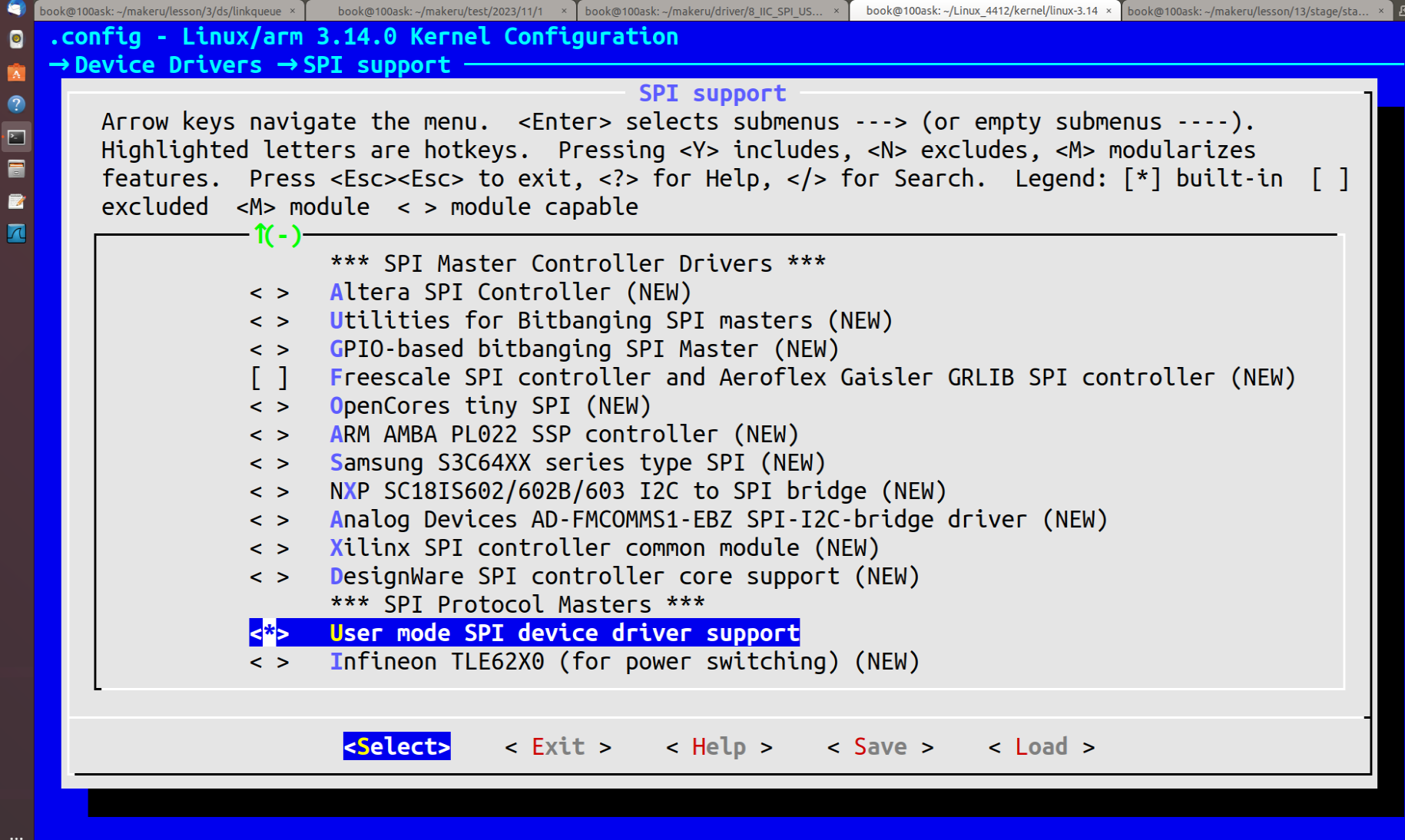
另外,也需要在设备树中添加一个 SPI 设备节点,用于匹配 spidev 驱动,设备节点至少包含如下内容。
SPI应用层驱动主要使用 ioctl 对 SPI 设备进行操作,常用的命令如下。
SPI_IOC_RD_MODE:获取 SPI主机控制器的模式。
SPI_IOC_WR_MODE:设置 SPI主机控制器的模式
SPI_IOC_RD_BITS_PER_WORD:获取 SPI的字长。
SPI_IOC_WR_BITS_PER_WORD: 设置 SPI的字长。
SPI_IOC_RD_MAX_SPEED_HZ: 取 SPI的最高工作速率
SPI_IOC_WR_MAX_SPEED_HZ: 设置 SPI的最高工作速率
SPI_IOC_MESSAGE(N): 执行N个传输事务。
应用层要通过 SPI 进行数据的传输也是用消息描述的,消息内部也包含传输事务应用层的传输事务的数据结构如下。
struct spi_ioc_transfer  {
    __u64    tx_buf;
    __u64    rx_buf;

    __u32    len;
    __u32    speed_hz;

    __u16    delay_usecs;
    __u8     bit_per_word;
    __u8     cs_change;
    __u32    pad;

};
tx_buf: 发送数据的缓冲区,不发送数据可以为 NULL
rx_buf: 接收数据的缓冲区,不接收数据可以为 NULL
len:传输的字节数。
speed_hz: 进行传输时,主机控制器的工作速率。
delay_usecs:片选信号无效的延时。
bits_per_word:传输使用的字长。
cs_change:如果非 0,表示在下一次传输前首先要将片选无效。
pad:用于结构大小控制。
应用层 SPI 设备驱动的编程步骤大致如下
(1)使用 open 打开/dev /spiB.C 设备。
(2) 使用 ioctl 函数和 SPI_IOC_WR_MODE、SPI_IOC_WR_BITS_PER_WORD、
SPI_IOC_WR_MA_SPEED_HZ 命令设置好工作模式、字长和工作速率。
(3)构造 struct spi_ioc_transfer 结构对象,设置好要发送的数据和数据长度等信息
(4)使用 ioctl 函数和 SPI_IOC_MESSAGE(N)命令执行传输操作,如果有读取的数据则当 SPI_IOC_MESSAGE(N)命令执行完成后,可以从 struct spi_ioc_transfer 结构对象的接收缓冲区中获取。
(5) 不使用设备时,用 close 关闭设备文件
三、 SPI设备驱动范例
应用层的 SPI 设备驱动的代码形式如下。
....
11 #include <linux/types,h>
12 #include <linux/spi/spidev.h>
13
14 int main(int argc, char **argv)
15 {
16    int fd;
17    unsigned char mode = SPI_MODE_0;
18    struct spi_ioc_transfer xfer[2];
19    unsigned char tx_buf[32];
20    unsigned char rx_buf[32];
21    int status;
22
23    fd = open ("/dev/spidev2.0",O_RDWR);
24    if (fd<0)
25        goto fai1;
26
27    if (ioctl(fd,SPI_IOC_WR_MODE, mode) < 0)
28        goto fail;
29
30    memset(xfer,  0, sizeof(xfer));
31    memset(tx_buf, 0, sizeof(tx_buf));
32    memset(rx_buf, 0, sizeof(rx_buf));
33    tx_buf[0] = 0xAA;
34    xfer[0].tx_buf = (unsigned long)tx_buf;
35    xfer[0].len = 1;
36
37    if(ioctl(fd,SPI_IOC_MESSAGE(1),xfer) < 0)
38        goto fail;
39
40    close(fd);
41
42    return 0;
43
44 fail:
45    perror("spi test");
46    exit(EXIT_FAILURE);
47}
首先要包含头文件 linux/spi/spidev.h,代码第 23 行打开了 SPI 设备文件。代码第 27行设置了 SPI 主机控制器的工作模式为 SPI_MODE_0,这要根据操作的具体 SPI 设备而定,通常在设备的数据手册上能够查阅到相关的内容。xfer 是传输事务结构对象,一个对象对应一个传输事务。代码第 30 行至第 35 行初始化了传输事务,并初始化了发送缓冲区内的内容。一次需要执行多少个传输事务需要根据实际的情况而定,发送缓冲区的内容也要根据实际情况而定,通常是操作 SPI 设备的一些命令。代码第 37 行执行传输,因为只有一个传输事务,所以命令为 SPI_IOC_MESSAGE(1),参数为 xfer,即传输事务对象的地址。
内核层的 SPI设备驱动代码形式如下。
13 #include <linux/spi/spi.h>
14
15 struct xxx_dev {
16    struct spi_device *spi;
17    atomic_t available;
18    struct cdev cdev;
19 };
20
......

42 static ssize_t xxx_read(struct file *filp, const char __user *buf,  size_t count, loff_t *pos)
43{
44    struct xxx_dev *xxx = filp->private_data;
45    unsigned char rx_buf[256];
46
47    spi_read(xxx->spi, rx_buf, count);
48    copy_to_user(buf, rx_buf, count);
49}
50
5l static ssize_t xxx_write(struct file *filp, const char __user *buf, size_t count, loff_t *pos)
52{
53    struct xxx_dev *xxx = filp->private_data;
54    unsigned char tx_buf[256];
55
56    copy_from_user(tx_buf, buf, count);
57    spi_write(xxx->spi,tx_buf,count);
58}
59
60static long xxx_ioctl(struct file *filp, unsigned int cmd, unsigned long arg)
61{
62    struct xxx_dev *xxx = filp->private_data;
63    unsigned char tx_buf[256];
64    unsigned char rx_buf[256];
65    struct spi_transfer_t = {
66        .tx_buf = tx_buf,
67        .rx_buf = rx_buf,
68        .len = _IOC_SIZE(cmd),
69    };
70    struct spi_message m;
71    int ret;
72
73    switch (cmd) {
74        case XXX_CMD:
75            copy_from_user(tx_buf,(void __user *)arg, __IOC_SIZE(cmd));
76            spi_message_init(&m);
77            spi_message_add_tail(&t,&m);
78            ret = spi_sync(xxx->spi,&m);
79            break;
80        default:
81            return -ENOTTY;
82    }
83
84    return 0;
85}
86
87 static struct file_operations xxx_ops = (
88    .owner = THIS_MODULE,
89    .open = xxx_open,
90    .release = xxx_release,
91    .read = xxx_read.
92    .write = xxx_write,
93    .unlocked_ioctl = xxx_ioctl,
94 };
95
96 static int xxx_probe(struct spi_device *spi)
97{
98     struct xxx_dev *xxx;
99
100    spi->mode = SPI_MODE0;
101    spi->bits_per_word = 8;
102    spi_setup(spi);
103
104
105    xxx = kzalloc(sizeof(struct xxx_dev),GFP_KERNEL);
106    spi_set_drvdata(spi,xxx);
107
108    return 0;
109 }
110
111 static int xxx_remove(struct spi_device *spi)
112{
113    struct xxx_dev *xxx = spi_get_drvdata(spi);
114
115    kfree(xxx);
116    return 0;
117}
118
119 static const struct spi_device_id xxx_id_table[] ={
120    {
121        .name = "xxx",
122    },
123    {}
124};
125 MODULE_DEVICE_TABLE(spi,xxx_id_table);
126
127 static struct spi_driver xxx_driver = {
128    .driver = {
129        .name = “xxx",
130        .owner = THIS_MODULE,
131    },
132    .id_table = xxx_id_tabler
133    .probe = xxx_probe,
134    .remove = xxx_remove,
135 };
136
137 module_spi_driver(xxx_driver);
138
139 MODULE_LICENSE("GPL");
(这块板子上没有对应的传感器,所以就XXX了)
首先要包含 linux/spi/spi.h 头文件,在设备的结构中包含 struct spi_device *类型的 spi成员,它是指向 SPI 设备的对象指针,在 probe 函数中传入,保存后可以方便以后使用
代码第 119 行至第 135 行是 SPI驱动的设备 id 表、SPI 驱动的结量定义和驱动的注册、注销,这和前面的平台驱动、I2C 驱动都非常类似。
在xxx_probe函数中,设置了 SPI设备结构对象中的工作模式和字长,并使用 spi_setup对 SPI 主机控制器进行了设置,模式和字长需要根据具体的设备而定。spi_set_drvdata 以及 xxx_remove 函数中的 spi_get_drvdata 用于设置和获取驱动数据,这在前面的平台驱动和 I2C 驱动中也有类似的代码。
xxx_read 函数中直接使用 spi_read 去读取 SPI设备,这是内核提供的一个简化的读取操作,但是实际如何读取 SPI 的数据,还要根据 SPI 设备的数据手册而定,通常可能会先发送一些命令,然后才能读取数据。
xxx_write 函数直接使用 spi_write 函数去写 SPI 设备,但是通常情况下,SPI设备接收到数据后也会返回一些数据,比如状态信息等,可以在写之后再来获取这些状态,或者是边写边获取状态。
xxx_ioctl 函数则是用传输事务和消息来对 SPI 设备进行访问操作的,这是更一般的形式。过程也和前面谈到的类似,首先初始化传输事务,然后使用 spi_message_init 函数初始化消息,接下来用 spi_message_add_tail 将传输事务添加到消息中的传输事务链表的尾部,最后使用 spi_sync 同步执行传输操作,返回的数据可以从传输事务的接收缓冲区中获取。
(由于没有对应设备具体使用就先没有啦,过几天我的毕设设备到了会有实物展示和对应实际传感器的代码和操作)