要做回航充电,又不想加其他的传感器,只能靠lidar来识别充电桩的形状定位。
显然,充电桩表面是平整的直线,那么就要从那么多点中提取直线,然后再识别哪一条直线是充电桩。提取直线就成为了最初的一步。
GitHub上一个比较好的开源库:GitHub - kam3k/laser_line_extraction: A ROS package that extracts line segments from LaserScan messages.
效果还不错
topics
订阅的topic显然是 scan,发布了两个topic,我们要用的是/line_segments,/line_markers是用来在rviz上显示的,可以在launch中关闭。
配置
配置列表如下,基本上都好理解,被我分成了三大类,便于理解。
frame_id (default: "laser")  # The frame in which the line segments are published.
scan_topic (default: "scan")  # The LaserScan topic.
publish_markers (default: false) # Whether or not markers are published.

-----------------------------------------------------------------------------------------------------

bearing_std_dev (default: 0.001)  # The standard deviation of bearing uncertainty in the laser scans (rad).
least_sq_angle_thresh (default: 0.0001) # Change in angle (rad) threshold to stop iterating least squares (least_sq_radius_thresh must also be met).
least_sq_radius_thresh (default: 0.0001) # Change in radius (m) threshold to stop iterating least squares (least_sq_angle_thresh must also be met).
range_std_dev (default: 0.02) # The standard deviation of range uncertainty in the laser scans (m).

---------------------------------------------------------------------------------------------------------

max_line_gap (default: 0.4) # The maximum distance between two points in the same line (m).
min_line_length (default: 0.5) # Lines shorter than this are not published (m).
min_line_points (default: 9) # Lines with fewer points than this are not published.
min_range (default: 0.4) # Points closer than this are ignored (m).
min_split_dist (default: 0.05) # When performing "split" step of split and merge, a split between two points results when the two points are at least this far apart (m).
# 线段split的阈值,过大时很多线段被合并成一条,过小时,出现很多碎短的线段
outlier_dist (default: 0.05) # Points who are at least this distance from all their neighbours are considered outliers (m).
消息
最重要的是我们拿到 /line_segments的消息之后如何分析
消息类型是LineSegmentsList,如下,这不是主要的。
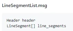
每个segment的类型LineSegment才是最主要的:
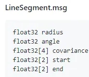
其中的start, end都好理解:
-
start 和end分别是这个线段的起点坐标和终点坐标
- covariance是关于radius和angle的 2x2 的协方差矩阵
-
radius和angle就不好理解了,于是我们echo了它的消息,如下
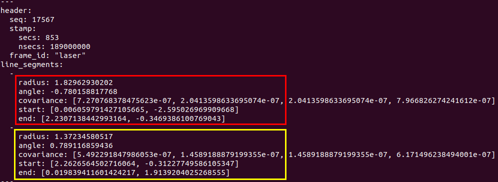
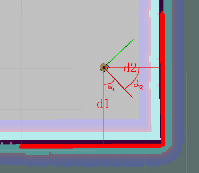
上图中一共找到了两条直线,下方的直线和右侧方的直线, 分别对应上上图中的红色框和黄色框中的内容。
按照ros中的坐标系来说,机器人正前方为0度,逆时针为正,激光数据的排列是从-90~90度(我的激光扫描范围是180度),那么上面2个线段从左往右依次是1,2。
这样的话我们就能理解 radius和angle的意思了。官方给的解释是极坐标下参数,我们能够理解到的是:
angle: 机器人原点到直线的垂线的角度,角度以机器人为坐标系计算,范围是-PI~PI
radius: 机器人原点到直线的距离
那么红色框对应机器人下方直线 :
radius = d1 = 1.82962930202;
angle = α1 = -0.780158817768;
黄色框对应机器人右侧方直线:
radius = d1 = 1.37234580517;
angle = α1 = 0.789116859436;