1 串口的协议
串口的全称是通用异步收发传输器,主要用于数据间的串行传递,是一种全双工传输模式。它在发送数据时将并行的数据转换成串行数据来传输,在接收数据时,将收到的串行数据转化为并行数据。
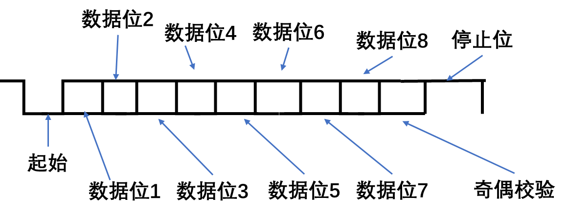
uart在发送或者接收过程中的一帧数据由4部分组成,包括起始位、数据位、奇偶校验位和停止位。其中起始位标志着一帧数据的开始,停止位标志着一帧数据的结束。数据位是一帧数据中的有效数据,校验位可以分为奇校验还是偶校验。
起始位:
tx传输信号默认是低电平,当出现一个下降沿,且持续一个bit的时间的低电平,则认为传输了一个起始位
数据位
是传输的有效数据,数据的位宽是可以选择的,6,7,8位。
校验位:
可以对传输的数据的正确性进行一定程度的检查
停止位:
持续一个bit时间长的高电平,则认为是数据的结束
如下如所示:(数据位宽是一个字节)
波特率
对于波特率,表示一秒内需要传输多少bit的数据,比如9600bps,就是表示一秒要传播9600bit。
2 串口发送模块

信号的解释:
| clk | 时钟 |
|---|---|
| rst_n | 复位 |
| tx_data | 发送的一字节的数据 |
| tx_en | 发送数据的使能信号,为一个高脉冲 |
| byte_finish | 成功发射了一字节的数据 |
| tx | 发送的信号 |
设计的整体思路
总体思路是设计一个状态机,有五个状态,空闲状态(IDLE),开始状态(START)、发送数据(SEND_DATA)、校验(EVEN_ODD_CHECK)和停止(STOP)。
首先对于全局的数据放在一个文件中config.v中,其中代码如下:
`define CLK_FRE 50_000_000      //输入的时钟频率
`define BAUD_RATE 115200          //波特率
`define EVEN_CHECK 1            //1 :偶校验  0:奇校验
uart_tx的模块代码如下:
`include "config.v"
module uart_tx (
    input   wire                    clk         ,
    input   wire                    rst_n       ,
    input   wire    [7:0]           tx_data     ,
    input   wire                    tx_en       ,

    output  wire                    byte_finish ,
    output  reg                     tx
);

    localparam      IDLE            =   5'b00001    ,       //空闲
                    START           =   5'b00010    ,       //起始
                    SEND_DATA       =   5'b00100    ,       //发送数据
                    EVEN_OLD_CHECK  =   5'b01000    ,       //奇偶校验
                    STOP            =   5'b10000    ;       //停止


    localparam      CNT_MAX         =   `CLK_FRE / `BAUD_RATE ;

    reg     [31:0]  cnt         ;
    reg     [4:0]   state       ;
    reg     [4:0]   nx_state    ;
    reg     [2:0]   cnt_data    ;
    reg             even_check  ;
    reg             odd_check   ;

    wire            start_finish;       //起始位结束信号
    wire            bit_flag    ;       //发送每个数据的bit信号
    wire            byte_flag   ;       //成功发送一字节数据的标致
    wire            check_flag  ;       //奇偶校验的标志
    wire            stop_flag   ;       //停止位的标志
    wire            check       ;       //要发送的奇偶校验信号


    assign start_finish = (state == START) && (cnt == CNT_MAX - 1) ? 1'b1 : 1'b0;
    assign bit_flag     = (state == SEND_DATA) && (cnt == CNT_MAX - 1) ? 1'b1 : 1'b0;
    assign byte_flag    = bit_flag && (cnt_data == 3'd7) ? 1'b1 : 1'b0;
    assign check_flag = ((state == EVEN_OLD_CHECK) && (cnt == CNT_MAX - 1)) ? 1'b1 : 1'b0;
    assign stop_flag = ((state == STOP) && (cnt == CNT_MAX - 1)) ? 1'b1 : 1'b0;
    assign check = `EVEN_CHECK ? even_check : odd_check;
    //状态转移(时序逻辑)
    always @(posedge clk or negedge rst_n) begin
        if(!rst_n) begin
            state <= IDLE;
        end
        else begin
            state <= nx_state;
        end
    end

    //状态跳转(组合逻辑)
    always @(*) begin
        //nx_state <= IDLE;
        case(state)
            IDLE:       nx_state = (tx_en) ? START : IDLE;
            START:      nx_state =  (start_finish) ? SEND_DATA : START;
            SEND_DATA:  nx_state = byte_flag ? EVEN_OLD_CHECK : SEND_DATA;
            EVEN_OLD_CHECK: nx_state = check_flag ? STOP : EVEN_OLD_CHECK;
            STOP:       nx_state = stop_flag ? IDLE : STOP;
            default:    nx_state = IDLE;
        endcase
    end
    //对cnt计数器赋值
    always @(posedge clk or negedge rst_n) begin
        if(!rst_n) begin
            cnt <= 'd0;
        end
        else begin
            case(state)
            IDLE:       cnt <= 'd0;
            START:  begin
                        if(nx_state == START) begin
                            cnt <= cnt + 1'b1;
                        end
                        else if(nx_state == SEND_DATA) begin
                            cnt <= 'd0;
                        end
                        else begin
                            cnt <= cnt;
                        end
                    end
            SEND_DATA:begin
                        if(nx_state == SEND_DATA) begin
                            if(bit_flag) begin
                                cnt <= 'd0;
                            end
                            else begin
                                cnt <= cnt + 1'b1;
                            end
                        end
                        else if(nx_state == EVEN_OLD_CHECK) begin
                            cnt <= 'd0;
                        end
                        else begin
                            cnt <= cnt;
                        end
                    end
            EVEN_OLD_CHECK: cnt <= (nx_state == EVEN_OLD_CHECK) ? cnt + 1'b1 : (nx_state == STOP) ? 'd0 : cnt;
            STOP:   cnt <= (nx_state == STOP) ? cnt + 1'b1 : 1'b0;
            default:cnt <= 'd0;
            endcase
        end
    end
    //统计发送的数据的bit数
    always @(posedge clk or negedge rst_n) begin
        if(!rst_n) begin
            cnt_data <= 3'd0;
        end
        else if((state == SEND_DATA) && (cnt_data == 3'd7) && (bit_flag)) begin
            cnt_data <= 'd0;
        end
        else if((state == SEND_DATA) && (cnt_data < 3'd7) && (bit_flag)) begin
            cnt_data <= cnt_data + 1'b1;
        end
        else begin
            cnt_data <= cnt_data;
        end
    end
    //生成奇校验还是偶校验
    always @(posedge clk or negedge rst_n) begin
        if(!rst_n) begin
            even_check <= 1'b0;
            odd_check <= 1'b0;
        end
        else if(tx_en) begin
            even_check <= ^tx_data;
            odd_check  <= ~(^tx_data);
        end
        else begin
            even_check <= even_check;
            odd_check <= odd_check;
        end
    end
    assign byte_finish = stop_flag;
    //发送数据
    always @(posedge clk or negedge rst_n) begin
        if(!rst_n) begin
            tx <= 1'b1;
        end
        else begin
            case(nx_state)
                IDLE:       tx <= 1'b1;
                START:      tx <= 1'b0;
                SEND_DATA:  tx <= bit_flag ? tx_data[cnt_data+1] : tx_data[cnt_data];
                EVEN_OLD_CHECK:tx <= check;
                STOP:       tx <= 1'b1;
                default:    tx <= 1'b1;
            endcase
        end
    end


endmodule
testbench如下:
`timescale 1ns/1ns
`define CLK_CYCLE 20

module tb_uart_tx;

    reg         clk         ;
    reg         rst_n       ;
    reg  [7:0]  tx_data     ;
    reg         tx_en       ;

    wire        byte_finish ;
    wire        tx          ;

    uart_tx     u_uart_tx(
    .  clk          (clk),
    .  rst_n        (rst_n),
    .  tx_data      (tx_data),
    .  tx_en        (tx_en),

    .  byte_finish  (byte_finish),
    .  tx           (tx)
);

initial begin
     clk = 1'b0;
     rst_n = 1'b0;
     tx_data = 8'h00;
     tx_en = 1'b0;
     #30
     rst_n = 1'b1;
     #100
     repeat (2) @(posedge clk);
     tx_en = 1'b1;
     tx_data = 8'h45;
     @(posedge clk);
     tx_en = 1'b0;
     @(negedge byte_finish);
     tx_en = 1'b1;
     tx_data = 8'h23;
     @(posedge clk);
     tx_en = 1'b0;
     @(byte_finish);
     #100
     $finish;
end

always #(`CLK_CYCLE / 2) clk = ~clk;

endmodule
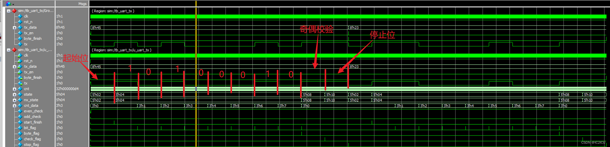
仿真波形如下,可知成功发射了数据。
3 串口接收模块

信号的解释:
| clk | 时钟 |
|---|---|
| rst_n | 复位 |
| tx | 接受到的单bit信号 |
| rx_data | 接收到的一个字节数据 |
| byte_finish | 一个字节数据接收的完成信号 |
| error | 基于奇偶校验,判断接收的数据是否可信 |
设计的整体思路
总体思路是设计一个状态机,有五个状态,空闲状态(IDLE),开始状态(START)、接收数据(RV_DATA)、校验(CHECK)和停止(STOP)。需要指出的一点是,对于数据采样,选择一个bit信号中间采样,这样采样的数据才是较为可靠的。
uart_rx的模块如下:
`include "config.v"

module uart_rx(
    input   wire                clk         ,
    input   wire                rst_n       ,
    input   wire                tx          ,

    output  wire    [7:0]       rx_data     ,
    output  reg                 error       ,
    output  wire                byte_finish
);

    localparam      IDLE    =       5'b00001    ,       //空闲
                    START   =       5'b00010    ,       //开始
                    RV_DATA =       5'b00100    ,       //接收数据
                    CHECK   =       5'b01000    ,       //奇偶校验
                    STOP    =       5'b10000    ;       //停止

    localparam      CNT_MAX     =   `CLK_FRE / `BAUD_RATE ;

    reg                     tx_dly      ;
    reg         [31:0]      cnt         ;
    reg         [4:0]       state       ;
    reg         [4:0]       nx_state    ;
    reg         [2:0]       cnt_bit     ;
    reg         [7:0]       rv_data     ;
    reg                     even_check  ;
    reg                     odd_check   ;

    wire                    tx_negedge  ;
    wire                    start_end   ;
    wire                    bit_flag    ;
    wire                    rv_end      ;
    wire                    sample_flag ;               //采样数据的信号
    wire                    check       ;
    wire                    check_end   ;
    wire                    stop_end    ;

    assign      start_end = (state == START) && (cnt == CNT_MAX - 2);

    assign      bit_flag = (state == RV_DATA) && (cnt == CNT_MAX - 1);

    assign      rv_end = (state == RV_DATA) && (bit_flag) && (cnt_bit == 3'd7);

    assign      sample_flag = ((state == RV_DATA) ) && (cnt == CNT_MAX / 2 - 1);

    assign      check = `EVEN_CHECK ? even_check : odd_check;

    assign      check_end = (state == CHECK) && (cnt == CNT_MAX - 1);

    assign      stop_end = (state == STOP) && (cnt == CNT_MAX - 1);

    always @(posedge clk or negedge rst_n) begin
        if(!rst_n) begin
            tx_dly <= 1'b1;
        end
        else begin
            tx_dly <= tx;
        end
    end

    assign  tx_negedge = ((tx_dly) && (!tx)) ? 1'b1 : 1'b0;

    always @(posedge clk or negedge rst_n) begin
        if(!rst_n) begin
            state <= IDLE;
        end
        else begin
            state <= nx_state;
        end
    end

    always @(*) begin
        case(state)
            IDLE:   nx_state = tx_negedge ? START : IDLE;
            START:  nx_state = start_end ? RV_DATA : START;
            RV_DATA:nx_state = rv_end ? CHECK : RV_DATA;
            CHECK:  nx_state = check_end ? STOP : CHECK;
            STOP:   nx_state = stop_end ? IDLE : STOP;
            default:nx_state = IDLE;
        endcase
    end

    always @(posedge clk or negedge rst_n) begin
        if(!rst_n) begin
            cnt <= 'd0;
        end
        else begin
            case(state)
            IDLE:       cnt <= 'd0;
            START:  begin
                        if(nx_state == START) begin
                            cnt <= cnt + 1'b1;
                        end
                        else if(nx_state == RV_DATA) begin
                            cnt <= 'd0;
                        end
                        else begin
                            cnt <= cnt;
                        end
                    end
            RV_DATA:begin
                        if(nx_state == RV_DATA) begin
                            if(bit_flag) begin
                                cnt <= 'd0;
                            end
                            else begin
                                cnt <= cnt + 1'b1;
                            end
                        end
                        else if(nx_state == CHECK) begin
                            cnt <= 'd0;
                        end
                        else begin
                            cnt <= cnt;
                        end
                    end
            CHECK:  cnt <= (nx_state == CHECK) ? cnt + 1'b1 : 'd0;
            STOP :  cnt <= (nx_state == STOP) ? cnt + 1'b1 : 'd0;
            default:cnt <= 'd0;
            endcase
        end
    end

    always @(posedge clk or negedge rst_n) begin
        if(!rst_n) begin
            cnt_bit <= 3'd0;
        end
        else if((bit_flag) && (nx_state == CHECK)) begin
            cnt_bit <= 3'd0;
        end
        else if(bit_flag) begin
            cnt_bit <= cnt_bit + 1'b1;
        end
        else begin
            cnt_bit <= cnt_bit;
        end
    end

    always @(posedge clk or negedge rst_n) begin
        if(!rst_n) begin
            rv_data <= 8'h00;
        end
        else if(state == IDLE) begin
            rv_data <= 8'h00;
        end
        else if(sample_flag) begin
            rv_data <= {

    tx, rv_data[7:1]};
        end
        else begin
            rv_data <= rv_data;
        end
    end

    always @(posedge clk or negedge rst_n) begin
        if(!rst_n) begin
            odd_check <= 1'b0;
            even_check <= 1'b0;
        end
        else if(nx_state == CHECK) begin
            even_check <= ^rv_data;
            odd_check <= ~(^rv_data);
        end
        else begin
            even_check <= even_check;
            odd_check <= odd_check;
        end
    end

    always @(posedge clk or negedge rst_n) begin
        if(!rst_n) begin
            error <= 1'b0;
        end
        else if(nx_state == IDLE) begin
            error <= 1'b0;
        end
        else if(nx_state == STOP) begin
            error <= 1'b0;
        end
        else if((nx_state == CHECK) && sample_flag) begin
            error <= (tx != check) ? 1'b1 : 1'b0;
        end
        else begin
            error <= error;
        end
    end

    assign rx_data = rv_data;

    assign byte_finish = (state == STOP) && (nx_state == IDLE);

endmodule
4 uart发送和接收模块的联合仿真
uart的顶层如下:

uart模块代码如下,就是把发送和接收模块连接
module uart(
    input   wire                clk         ,
    input   wire                rst_n       ,
    input   wire    [7:0]       tx_data     ,
    input   wire                tx_en       ,

    output  wire    [7:0]       rx_data     ,
    output  wire                error       ,
    output  wire                rv_byte_finish
);

    wire            tx_byte_finish  ;
    wire            tx              ;

    uart_tx     u_uart_tx(
    .  clk         (clk),
    .  rst_n       (rst_n),
    .  tx_data     (tx_data),
    .  tx_en       (tx_en),

    .  byte_finish (tx_byte_finish),
    .  tx (tx)
);

    uart_rx u_uart_rx(
    . clk         (clk),
    . rst_n       (rst_n),
    . tx          (tx),

    . rx_data     (rx_data),
    . error       (error),
    . byte_finish (rv_byte_finish)
);


endmodule
仿真代码如下:
`timescale 1ns/1ns
`define CLK_CYCLE 20

module tb_uart;

    reg         clk         ;
    reg         rst_n       ;
    reg  [7:0]  tx_data     ;
    reg         tx_en       ;

    wire [7:0]  rx_data     ;
    wire        error       ;
    wire        rv_byte_finish;

    uart    u_uart(
    .   clk       (clk),
    .   rst_n     (rst_n),
    .   tx_data   (tx_data),
    .   tx_en     (tx_en),

    .   rx_data   (rx_data),
    .   error     (error),
    .   rv_byte_finish(rv_byte_finish)
);

    initial begin
     clk = 1'b0;
     rst_n = 1'b0;
     tx_data = 8'h00;
     tx_en = 1'b0;
     #30
     rst_n = 1'b1;
     #100
     repeat (2) @(posedge clk);
     tx_en = 1'b1;
     tx_data = 8'h45;
     @(posedge clk);
     tx_en = 1'b0;
     @(negedge rv_byte_finish);
     tx_en = 1'b1;
     tx_data = 8'h23;
     @(posedge clk);
     tx_en = 1'b0;
     @(rv_byte_finish);
     #100
     $finish;
end

always #(`CLK_CYCLE / 2) clk = ~clk;


endmodule
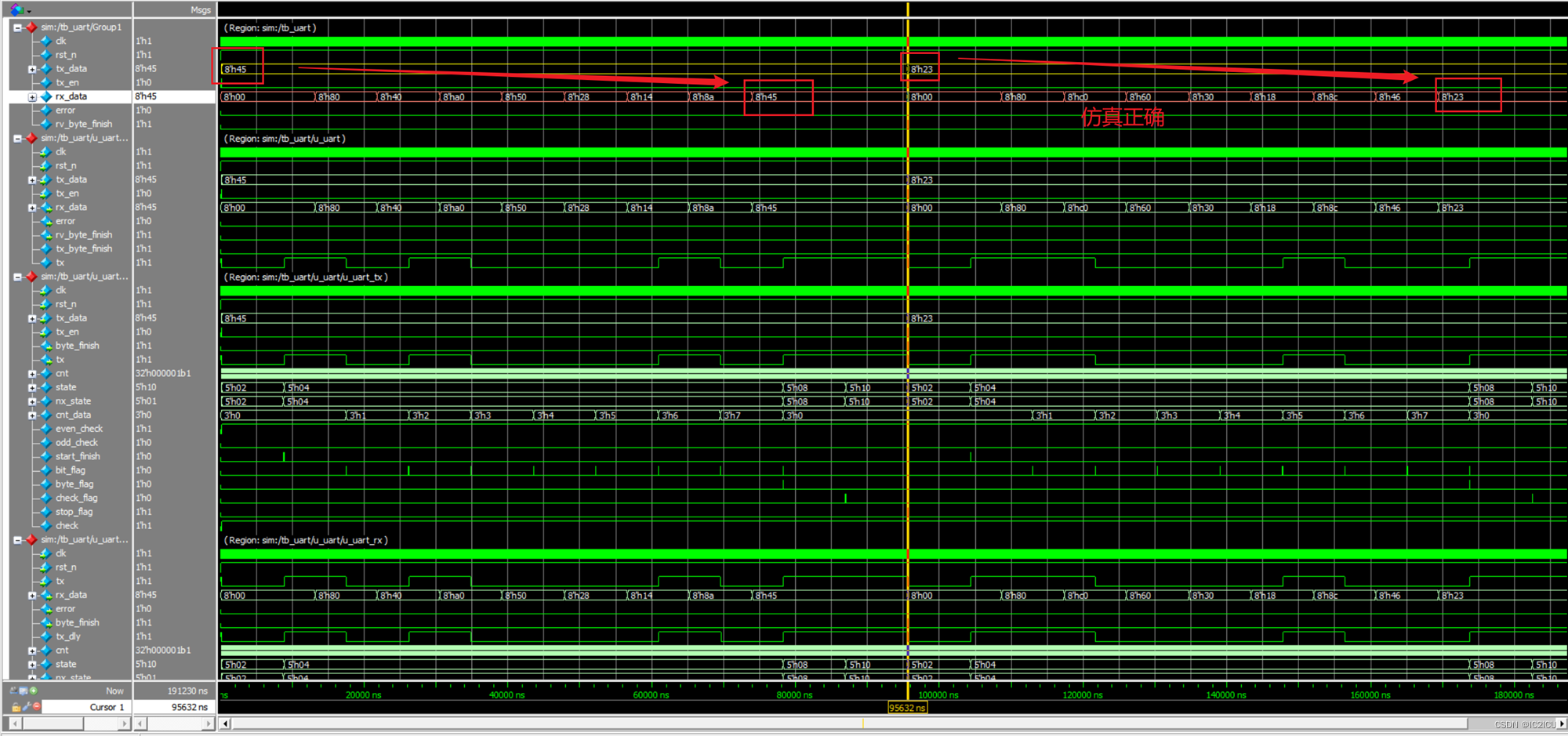
仿真波形如下,可见成功的接收到了数据。
5 总结
感觉自己对状态机的写法以及理解更加好了,至此三大通信协议都完成了。加油加油加油!!!