What is secure boot and how it work?
- What is secure boot ?
Secure boot is a secure mechanism/feature to protect system only allow CPU boot from complete and authorized binary images.
- How secure boot work on Rcar H3?
With this function, when System is booted, Boot ROM Program verifies whether IPL (initial program loader) binary image has not been tampered with. Also, Secure Boot function can be called from software, and by using this function software is designed to be able to ensure to launch the integrity binary images.

Boot sequence
Life Cycle Management(LCM)
R-Car Gen3 supports LCM (life cycle management) to control security level for each stage of life cycle. LCM states are determined by e-FUSE bits value.
| LCM state |
Description |
| Chip Manufacture(CM) |
This state indicates that all debugging capabilities of the chip are enabled. Device |
| Device Manufacture(DM) |
In this state, debugging capabilities are still enabled. Device unique key is |
| Secure Disable(SD) |
Used for marking devices that lack security functionality. |
| Secure(SE) |
This state permits the execution of security functions, but restricts the debugging |
| Failure Analysis(FA) |
Used for devices returned to the manufacture for analysis of fatal devices. |
ATF(arm-trust-firmware) will call romcode interface to read LCM state and show it as follow during system boot if you enable relevant debug log:

Usually the LCM state is determined at the time of production, and modification is generally not allowed, but in some specific cases, the state of the LCM can be changed by modifying the OEM-programmed flags in e-fuse. For example, the document "CSD_SI_17-055_R-CarGen3_Security_Users_Manual_v0p2.pdf" mentions:

In the following content, we will introduce how to change the LCM state of the SOC from DM to SE.
Boot sequence in different LCM states
The following figure shows the boot sequence in different LCM states.
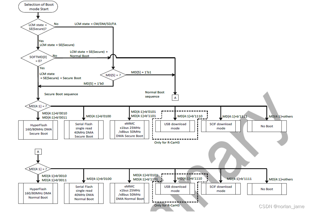
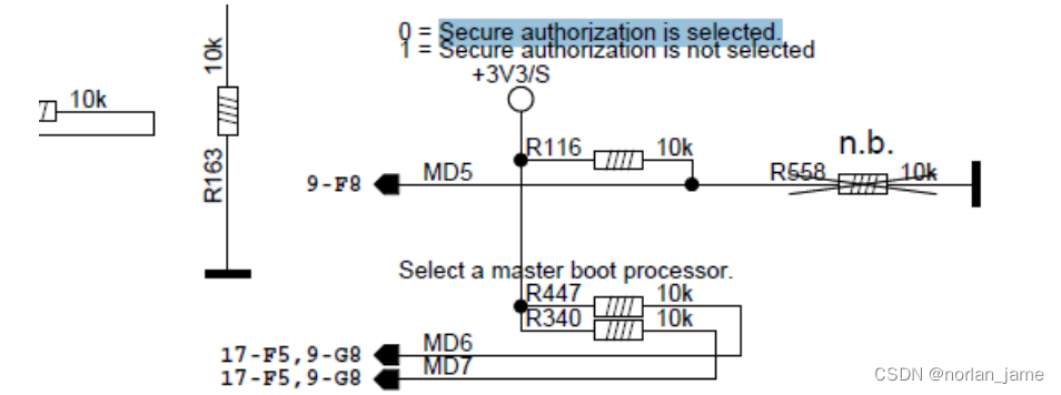
So from the above flow chart, even SOC is in non-SE mode, we can still debug the SE function by changing the evel state of the MD5 pin.
When the SE function is enabled, boot sequence from a software perspective:

The secure boot check function will work in the below two phases.
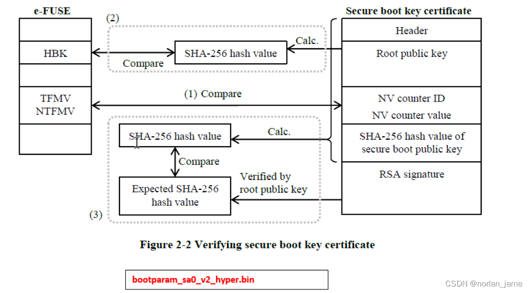
1. After the Reset,Cortex-A57, Cortex-A53 or Cortex-R7 master boot processor executes the instructions in the Boot ROM, and the first 5kbytes data(E.g bootparam_sa0_v2_hyper.bin) is transferred from serial flash ROM to the System RAM. then then call the secure boot API to check the integrity and authorization of IPL binary image. If the check passes, it will jump to the IPL. Otherwise, it will stop system boot after output error log.
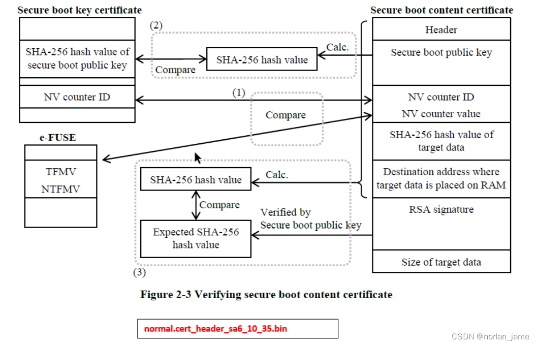
2. IPL will load the remaining images and content certificate(E.g normal.cert_header_sa6_10_35.bin), then it calls the secure boot API to check integrity and authorization of these binary images . If it passes, it will start up system normally. Otherwise, it will stop system boot after output error log
section Boot images Will introduce flashlayout of boot images, and the data structure of these images, briefly introduce the process of their generation.
Boot images
Flash-Layout
The figure below shows the flash-layout status of boot images.

These images including:
| Images |
Comments |
| bootparam_sa0_0.bin |
Boot parameter& root-key certificates |
| normal.cert_header_sa6_0_0.bin swupdate.cert_header_sa6_0_0.bin |
Content certificates: |
| Others |
Content images |
Images roadmap

❶ Create the content images by bob.
❷ Create key pairs by openssl or get them from signing server and fill configure parameters
❸ Create certificates files
❹ Create certificate image files.
Section secure boot key Certificate will describe the process details of the certificates file generation.
Data structure of image’s certificates
The data structure of bootparam_sa0_v2_hyper.bin is showed as follow:
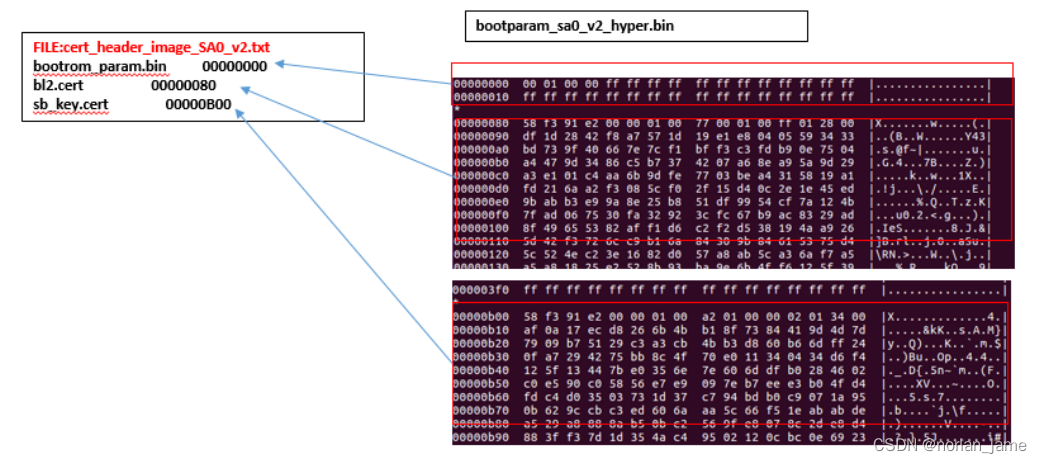
bootparam_sa0_v2_hyper.bin is created by the tool bin_create, and the tool bin_create just simply combines several certificates files as one binary image. sb_key.cert was created by cert_key_util.py and bl2.cert was created by the tool cert_sb_content_util.py.
Similarly, the data structure of normal.cert_header_sa6_10_35.bin is showed as follow:
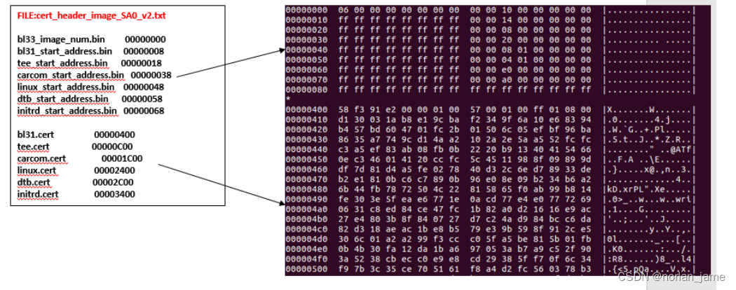
Other certificates files are also created by cert_sb_content_util.py.
Secure Boot Key Certificate
As described in the previous section, the following is the process of sb key.cert generation:

The following is the process of bl2.cert and others certificates file generation:
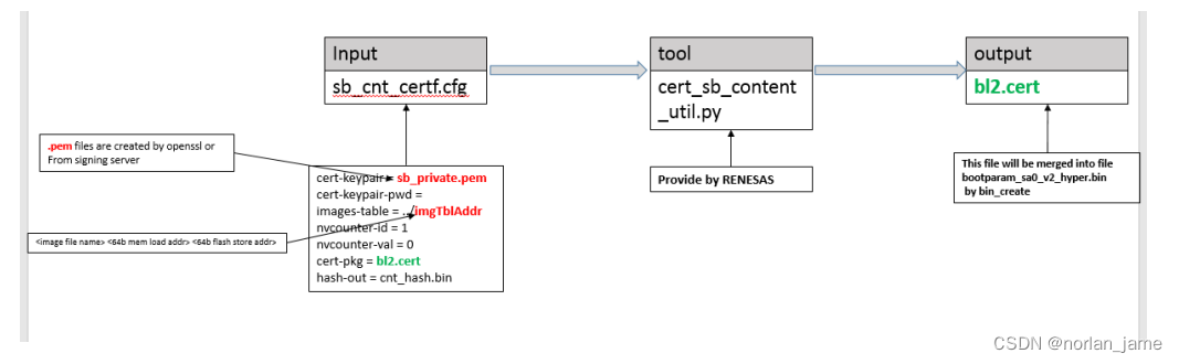
You can refer to RENESAS_RC3G_SecureBootSigningPCTool_UM_1_1_2.pdf to get more detail.
Verify secure boot function
After we implement secure boot function on H3/M3 and switch the LCM state of SOC from DM to SE, now we can verify our secure boot key and secure boot function.
Build boot image package with authorized root-key and flashing these images to flash device, you can get follow start up log:

If your root-key is un-authorized, you can get follow error log and it can't boot up normally.
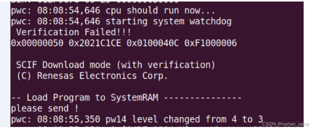
Please note that, if the LCM state of SOC is SE, you need re-build your minimontor(minimon_v1.mot or minimon_v2) with authorized key, otherwise it can't run successfully.
References
CSD_SI_17-055_R-CarGen3_Security_Users_Manual_v0p2.pdf
RENESAS_RC3G_SecureBootSigningPCTool_UM_1_1_2.pdf
RC3G_Secure_Boot_System_Architecture_Design_Guide_E_rev1.0.0.pdf
R-CarGen3_e-fuse_programming_guide_0003_e.pdf
RENESAS_RCH3M3M3N_SecureBootFunction_ApplicationNote_v1.0.4.pdf