移植后的效果如上图所示,采用的LVGL版本是8.2,接下来是详细的移植过程。
项目来源简单介绍
某天在某宝瞎逛时,突然发现一款单片机,最小系统板只有9.9,这不正好戳中老夫穷逼的心,想到就现在就一块F103最小系统板也得要20、30元,而且仔细一看主频240M,支持WiFi/蓝牙,好家伙我直呼太香,于是果断入手。

主控芯片介绍
W801 芯片是基于平头哥XT804内核设计的soc芯片,支持2.4G IEEE802.11b/g/n Wi-Fi 通讯协议;支持 BT/BLE 双模工作模式,支持 BT/BLE4.2 协议。芯片集成32位 CPU 处理器,内置丰富数字接口;支持TEE安全引擎,支持多种硬件加解密算法,内置DSP、浮点运算单元与安全引擎,支持代码安全权限设置,内置2MBFlash存储器,支持固件加密存储、固件签名,适用于用于智能家居等广泛的物联网领域。
圆形屏幕
选择的是优信电子店铺下的,驱动芯片是GC9A01。
项目目标
最终是希望在W801芯片上实现开源项目SmartKonb智能旋钮开源项目的效果(其实做不到。。。)。
平台搭建和代码准备
1、安装剑池CDK
在平头哥官网下载,国产软件安装都很简单,几乎就是下一步,也没有破解的操作,直接上手就能用。
下载地址:https://occ.t-head.cn/product?id=3864775351511420928&type=soft2、下载串口烧录软件
去联盛德官网搜W800,找到下面的页面,下载Upgrade_Tools_V1.4.8,无需安装,解压双击就能运行:
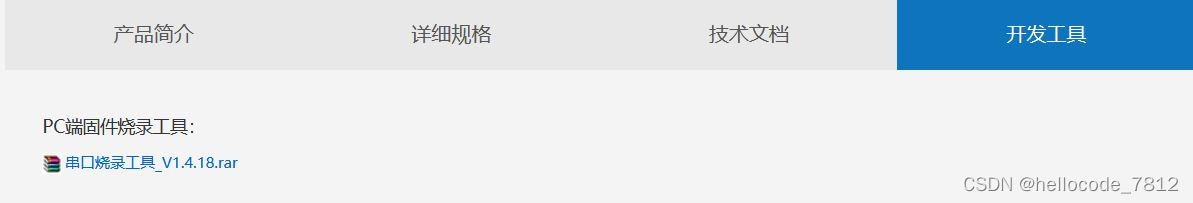
下载地址:https://www.winnermicro.com/html/1/156/158/558.html3、下载W800SDK代码
我使用的是在海凌科官网下载的wm_sdk_w80x_20211115,解压到本地后,在wm_sdk_w80x_20211115\tools\w800\projects\SDK_Project\project\CDK_WS\W800_SDK目录下找到W800_SDK.cdkproj,双击打开工程项目。
下载地址:https://www.hlktech.com/Goods-199.html4、下载LVGL-8.2和驱动代码代码
命令:git clone --recurse-submodules https://github.com/lvgl/lv_sim_visual_studio.git -b release/v8.2 命令:git clone --recurse-submodules https://github.com/lvgl/lv_drivers.git -b release/v8.2代码移植过程
1、前期代码准备
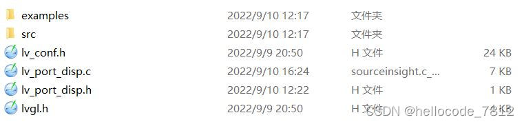
在wm_sdk_w80x_20211115目录下新建一个lvgl文件夹,将lvgl库下的src,examples文件夹和lvgl.h、lvgl_conf_template.h文件复制到新建目录下,并将lvgl_conf_template.h重命名为lvgl_conf.h

在examples目录下的porting文件夹中,将 lv_port_disp_template.c和lv_port_disp_template.h文件复制到lvgl目录下,并删除命名中的_template,删除porting文件夹。最终如下图所示:
2、代码编写
2.1、将LVGL库加载进入项目下
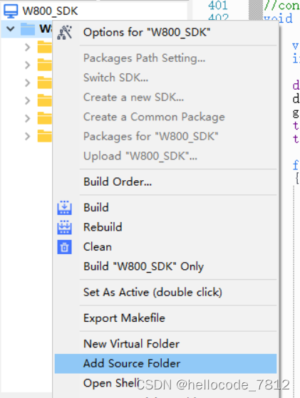
在CDK编辑器下,左侧项目结构右键选择Add Source Folder,并选择刚刚新建的lvgl目录,点击添加即可。
2.2、SPI驱动代码
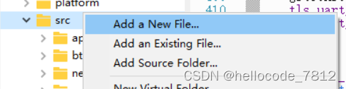
在工程项目src目录下右键选择新建文件lcd.h lcd.c lcd_spi_dirver.h lcd_spi_driver.c 四个文件 ,如下图所示:
代码如下
lcd.h
#ifndef _LCD_H_
#define _LCD_H_
#include "lcd.h"
#include "wm_gpio_afsel.h"

#define LCD_SCL        	WM_IO_PB_15 //--->>TFT --SCL
#define LCD_SDA        	WM_IO_PB_17 //--->>TFT --SDA
#define LCD_RST     	WM_IO_PB_24	//--->>TFT --RST
#define LCD_DC         	WM_IO_PB_25	//--->>TFT --RS/DC
#define LCD_CS        	WM_IO_PB_14 //--->>TFT --CS
#define LCD_BL        	WM_IO_PB_27 //--->>TFT --BL

#define LCD_DC_SET   do{ tls_gpio_write(LCD_DC, 1);} while(0)
#define LCD_LED_SET  do{ tls_gpio_write(LCD_BL, 1);} while(0)
#define LCD_RST_SET  do{ tls_gpio_write(LCD_RST,1);} while(0)

#define LCD_DC_CLR   do{ tls_gpio_write(LCD_DC, 0);} while(0)
#define LCD_LED_CLR  do{ tls_gpio_write(LCD_BL, 0);} while(0)
#define LCD_RST_CLR  do{ tls_gpio_write(LCD_RST,0);} while(0)


#define X_MAX_PIXEL	        (128)
#define Y_MAX_PIXEL	        (160)


#define RED  	0xF800
#define GREEN	0x07E0
#define BLUE 	0x001F
#define WHITE	0xFFFF
#define BLACK	0x0000
#define YELLOW  0xFFE0
#define GRAY0   0xEF7D
#define GRAY1   0x8410
#define GRAY2   0x4208


void LCD_GpioInit(void);

void LCD_Reset(void);

void LCD_Back_On(void);

void LCD_Back_Off(void);

void LCD_Init(void);


void LCD_Address_Set(u16 x_start, u16 y_start, u16 x_end, u16 y_end);

void LCD_Fill(u16 x_start, u16 y_start, u16 x_end, u16 y_end, u16 color);

void LCD_Clear(u16 Color);


#endif
lcd.c
#include "wm_include.h"
#include "lcd.h"
#include "wm_gpio_afsel.h"
#include "lcd_spi_driver.h"
#include "string.h"
/* GC9A01 Commands that we know of. Limited documentation */
#define GC9A01_INVOFF 0x20
#define GC9A01_INVON 0x21
#define GC9A01_DISPON 0x29
#define GC9A01_CASET 0x2A
#define GC9A01_RASET 0x2B
#define GC9A01_RAMWR 0x2C
#define GC9A01_COLMOD 0x3A
#define GC9A01_MADCTL 0x36
#define GC9A01_MADCTL_MY 0x80
#define GC9A01_MADCTL_MX 0x40
#define GC9A01_MADCTL_MV 0x20
#define GC9A01_MADCTL_RGB 0x00
#define GC9A01_DISFNCTRL 0xB6
/**********************
* TYPEDEFS
**********************/
/* Init script function */
struct GC9A01_function {
uint16_t cmd;
uint16_t data;
};
/* Init script commands */
enum GC9A01_cmd {
GC9A01_START,
GC9A01_END,
GC9A01_CMD,
GC9A01_DATA,
GC9A01_DELAY
};
// Documentation on op codes for GC9A01 are very hard to find.
// Will document should they be found.
static struct GC9A01_function GC9A01_cfg_script[] = {
{ GC9A01_START, GC9A01_START},
{ GC9A01_CMD, 0xEF},
{ GC9A01_CMD, 0xEB},
{ GC9A01_DATA, 0x14},
{ GC9A01_CMD, 0xFE}, // Inter Register Enable1
{ GC9A01_CMD, 0xEF}, // Inter Register Enable2
{ GC9A01_CMD, 0xEB},
{ GC9A01_DATA, 0x14},
{ GC9A01_CMD, 0x84},
{ GC9A01_DATA, 0x40},
{ GC9A01_CMD, 0x85},
{ GC9A01_DATA, 0xFF},
{ GC9A01_CMD, 0x86},
{ GC9A01_DATA, 0xFF},
{ GC9A01_CMD, 0x87},
{ GC9A01_DATA, 0xFF},
{ GC9A01_CMD, 0x88},
{ GC9A01_DATA, 0x0A},
{ GC9A01_CMD, 0x89},
{ GC9A01_DATA, 0x21},
{ GC9A01_CMD, 0x8A},
{ GC9A01_DATA, 0x00},
{ GC9A01_CMD, 0x8B},
{ GC9A01_DATA, 0x80},
{ GC9A01_CMD, 0x8C},
{ GC9A01_DATA, 0x01},
{ GC9A01_CMD, 0x8D},
{ GC9A01_DATA, 0x01},
{ GC9A01_CMD, 0x8E},
{ GC9A01_DATA, 0xFF},
{ GC9A01_CMD, 0x8F},
{ GC9A01_DATA, 0xFF},
{ GC9A01_CMD, GC9A01_DISFNCTRL}, // Display Function Control
{ GC9A01_DATA, 0x00},
{ GC9A01_DATA, 0x00},
{ GC9A01_CMD, GC9A01_MADCTL}, // Memory Access Control
{ GC9A01_DATA, 0x48}, // Set the display direction 0,1,2,3 four directions
{ GC9A01_CMD, GC9A01_COLMOD}, // COLMOD: Pixel Format Set
{ GC9A01_DATA, 0x05}, // 16 Bits per pixel
{ GC9A01_CMD, 0x90},
{ GC9A01_DATA, 0x08},
{ GC9A01_DATA, 0x08},
{ GC9A01_DATA, 0x08},
{ GC9A01_DATA, 0x08},
{ GC9A01_CMD, 0xBD},
{ GC9A01_DATA, 0x06},
{ GC9A01_CMD, 0xBC},
{ GC9A01_DATA, 0x00},
{ GC9A01_CMD, 0xFF},
{ GC9A01_DATA, 0x60},
{ GC9A01_DATA, 0x01},
{ GC9A01_DATA, 0x04},
{ GC9A01_CMD, 0xC3}, // Power Control 2
{ GC9A01_DATA, 0x13},
{ GC9A01_CMD, 0xC4}, // Power Control 3
{ GC9A01_DATA, 0x13},
{ GC9A01_CMD, 0xC9}, // Power Control 4
{ GC9A01_DATA, 0x22},
{ GC9A01_CMD, 0xBE},
{ GC9A01_DATA, 0x11},
{ GC9A01_CMD, 0xE1},
{ GC9A01_DATA, 0x10},
{ GC9A01_DATA, 0x0E},
{ GC9A01_CMD, 0xDF},
{ GC9A01_DATA, 0x21},
{ GC9A01_DATA, 0x0C},
{ GC9A01_DATA, 0x02},
{ GC9A01_CMD, 0xF0}, // SET_GAMMA1
{ GC9A01_DATA, 0x45},
{ GC9A01_DATA, 0x09},
{ GC9A01_DATA, 0x08},
{ GC9A01_DATA, 0x08},
{ GC9A01_DATA, 0x26},
{ GC9A01_DATA, 0x2A},
{ GC9A01_CMD, 0xF1}, // SET_GAMMA2
{ GC9A01_DATA, 0x43},
{ GC9A01_DATA, 0x70},
{ GC9A01_DATA, 0x72},
{ GC9A01_DATA, 0x36},
{ GC9A01_DATA, 0x37},
{ GC9A01_DATA, 0x6F},
{ GC9A01_CMD, 0xF2}, // SET_GAMMA3
{ GC9A01_DATA, 0x45},
{ GC9A01_DATA, 0x09},
{ GC9A01_DATA, 0x08},
{ GC9A01_DATA, 0x08},
{ GC9A01_DATA, 0x26},
{ GC9A01_DATA, 0x2A},
{ GC9A01_CMD, 0xF3}, // SET_GAMMA4
{ GC9A01_DATA, 0x43},
{ GC9A01_DATA, 0x70},
{ GC9A01_DATA, 0x72},
{ GC9A01_DATA, 0x36},
{ GC9A01_DATA, 0x37},
{ GC9A01_DATA, 0x6F},
{ GC9A01_CMD, 0xED},
{ GC9A01_DATA, 0x1B},
{ GC9A01_DATA, 0x0B},
{ GC9A01_CMD, 0xAE},
{ GC9A01_DATA, 0x77},
{ GC9A01_CMD, 0xCD},
{ GC9A01_DATA, 0x63},
{ GC9A01_CMD, 0x70},
{ GC9A01_DATA, 0x07},
{ GC9A01_DATA, 0x07},
{ GC9A01_DATA, 0x04},
{ GC9A01_DATA, 0x0E},
{ GC9A01_DATA, 0x0F},
{ GC9A01_DATA, 0x09},
{ GC9A01_DATA, 0x07},
{ GC9A01_DATA, 0x08},
{ GC9A01_DATA, 0x03},
{ GC9A01_CMD, 0xE8},
{ GC9A01_DATA, 0x34},
{ GC9A01_CMD, 0x62},
{ GC9A01_DATA, 0x18},
{ GC9A01_DATA, 0x0D},
{ GC9A01_DATA, 0x71},
{ GC9A01_DATA, 0xED},
{ GC9A01_DATA, 0x70},
{ GC9A01_DATA, 0x70},
{ GC9A01_DATA, 0x18},
{ GC9A01_DATA, 0x0F},
{ GC9A01_DATA, 0x71},
{ GC9A01_DATA, 0xEF},
{ GC9A01_DATA, 0x70},
{ GC9A01_DATA, 0x70},
{ GC9A01_CMD, 0x63},
{ GC9A01_DATA, 0x18},
{ GC9A01_DATA, 0x11},
{ GC9A01_DATA, 0x71},
{ GC9A01_DATA, 0xF1},
{ GC9A01_DATA, 0x70},
{ GC9A01_DATA, 0x70},
{ GC9A01_DATA, 0x18},
{ GC9A01_DATA, 0x13},
{ GC9A01_DATA, 0x71},
{ GC9A01_DATA, 0xF3},
{ GC9A01_DATA, 0x70},
{ GC9A01_DATA, 0x70},
{ GC9A01_CMD, 0x64},
{ GC9A01_DATA, 0x28},
{ GC9A01_DATA, 0x29},
{ GC9A01_DATA, 0xF1},
{ GC9A01_DATA, 0x01},
{ GC9A01_DATA, 0xF1},
{ GC9A01_DATA, 0x00},
{ GC9A01_DATA, 0x07},
{ GC9A01_CMD, 0x66},
{ GC9A01_DATA, 0x3C},
{ GC9A01_DATA, 0x00},
{ GC9A01_DATA, 0xCD},
{ GC9A01_DATA, 0x67},
{ GC9A01_DATA, 0x45},
{ GC9A01_DATA, 0x45},
{ GC9A01_DATA, 0x10},
{ GC9A01_DATA, 0x00},
{ GC9A01_DATA, 0x00},
{ GC9A01_DATA, 0x00},
{ GC9A01_CMD, 0x67},
{ GC9A01_DATA, 0x00},
{ GC9A01_DATA, 0x3C},
{ GC9A01_DATA, 0x00},
{ GC9A01_DATA, 0x00},
{ GC9A01_DATA, 0x00},
{ GC9A01_DATA, 0x01},
{ GC9A01_DATA, 0x54},
{ GC9A01_DATA, 0x10},
{ GC9A01_DATA, 0x32},
{ GC9A01_DATA, 0x98},
{ GC9A01_CMD, 0x74},
{ GC9A01_DATA, 0x10},
{ GC9A01_DATA, 0x85},
{ GC9A01_DATA, 0x80},
{ GC9A01_DATA, 0x00},
{ GC9A01_DATA, 0x00},
{ GC9A01_DATA, 0x4E},
{ GC9A01_DATA, 0x00},
{ GC9A01_CMD, 0x98},
{ GC9A01_DATA, 0x3E},
{ GC9A01_DATA, 0x07},
{ GC9A01_CMD, 0x35}, // Tearing Effect Line ON
{ GC9A01_CMD, 0x21}, // Display Inversion ON
{ GC9A01_CMD, 0x11}, // Sleep Out Mode
{ GC9A01_DELAY, 120},
{ GC9A01_CMD, GC9A01_DISPON}, // Display ON
{ GC9A01_DELAY, 255},
{ GC9A01_END, GC9A01_END},
};
//液晶IO初始化配置
void LCD_GpioInit(void)
{
int clk = 20000000; // 2 M
int type = 2; // 2 DMA
/*MASTER SPI configuratioin*/
wm_spi_cs_config(LCD_CS);
wm_spi_ck_config(LCD_SCL);
wm_spi_do_config(LCD_SDA);
tls_gpio_cfg(LCD_BL, WM_GPIO_DIR_OUTPUT, WM_GPIO_ATTR_PULLHIGH);
tls_gpio_cfg(LCD_DC, WM_GPIO_DIR_OUTPUT, WM_GPIO_ATTR_PULLHIGH);
tls_gpio_cfg(LCD_RST, WM_GPIO_DIR_OUTPUT, WM_GPIO_ATTR_PULLHIGH);
tls_spi_trans_type(SPI_DMA_TRANSFER);
tls_spi_setup(TLS_SPI_MODE_3, TLS_SPI_CS_LOW, clk);
}
void LCD_Reset(void)
{
LCD_RST_SET;
tls_os_time_delay(50);
LCD_RST_CLR;
tls_os_time_delay(50);
LCD_RST_SET;
tls_os_time_delay(50);
}
void LCD_Back_On(void)
{
LCD_LED_SET;
}
void LCD_Back_Off(void)
{
LCD_LED_CLR;
}
static void LCD_WriteReg(u8 reg)
{
S_WriteReg(reg);
}
static void LCD_WriteData8(u8 data)
{
S_WriteData8(data);
}
static void LCD_WriteData16(u16 data)
{
S_WriteData16(data);
}
static void LCD_WriteData(u8 *data, u32 len)
{
u32 t1 = 0, t2 = 0;
t1 = tls_os_get_time();
S_WriteData(data, len);
t2 = tls_os_get_time();
printf("s %d use %d\n", len, t2 - t1);
}
//
static void LCD_run_cfg_script(void)
{
int i = 0;
int end_script = 0;
do {
switch (GC9A01_cfg_script[i].cmd)
{
case GC9A01_START:
break;
case GC9A01_CMD:
LCD_WriteReg( GC9A01_cfg_script[i].data & 0xFF );
break;
case GC9A01_DATA:
LCD_WriteData8( GC9A01_cfg_script[i].data & 0xFF );
break;
case GC9A01_DELAY:
tls_os_time_delay(GC9A01_cfg_script[i].data);
break;
case GC9A01_END:
end_script = 1;
}
i++;
} while (!end_script);
}
void LCD_Init(void)
{
//初始化GPIO
LCD_GpioInit();
tls_gpio_write(LCD_CS,FALSE);
LCD_Reset();
LCD_Back_On();
//配置GC9A01驱动
LCD_run_cfg_script();
}
void LCD_Address_Set(uint16_t x0, uint16_t y0, uint16_t x1, uint16_t y1)
{
uint16_t x_start = x0, x_end = x1;
uint16_t y_start = y0, y_end = y1;
LCD_WriteReg(GC9A01_CASET); // Column addr set
LCD_WriteData8(x_start >> 8);
LCD_WriteData8(x_start & 0xFF); // XSTART
LCD_WriteData8(x_end >> 8);
LCD_WriteData8(x_end & 0xFF); // XEND
LCD_WriteReg(GC9A01_RASET); // Row addr set
LCD_WriteData8(y_start >> 8);
LCD_WriteData8(y_start & 0xFF); // YSTART
LCD_WriteData8(y_end >> 8);
LCD_WriteData8(y_end & 0xFF); // YEND
LCD_WriteReg(GC9A01_RAMWR);
}
// 整个屏幕填充颜色
void LCD_Clear(u16 Color)
{
// LCD_Fill(0, 0, X_MAX_PIXEL, Y_MAX_PIXEL, Color);
LCD_Address_Set(0,0,X_MAX_PIXEL-1,Y_MAX_PIXEL-1);
LCD_WriteReg(0x2C);
u32 total = X_MAX_PIXEL * Y_MAX_PIXEL * 2;
u8 High_8bit = Color>>8;
u8 Low_8bit = Color;
u8 *data = tls_mem_alloc(8160);
if(data == NULL) {
printf("mem null\n");
return;
}
else {
memset(data, Low_8bit, 8160);
for(int i = 0; i<8160; i+=2)
{
data[i] = High_8bit;
}
}
u16 body = total/8160;
u16 tail = total%8160;
if(body > 0)
{
do
{
S_WriteData((u8 *)data, 8160);
} while (--body);
}
if(tail > 0)
{
S_WriteData((u8 *)data, tail);
}
tls_mem_free(data);
}
lcd_spi_driver.h
#ifndef __LCD_SPI_DRIVER_H__
#define __LCD_SPI_DRIVER_H__
#include "wm_include.h"

void S_WriteReg(u8 reg);

void S_WriteData8(u8 data);

void S_WriteData16(u16 data);

void S_WriteData(u8 *data, u32 len);

#endif
lcd_spi_driver.c
#include "wm_include.h"
#include "lcd_spi_driver.h"
#include "wm_hostspi.h"
#include "lcd.h"
void S_WriteReg(u8 reg)
{
LCD_DC_CLR;
tls_spi_write(®, 1);
LCD_DC_SET;
}
void S_WriteData8(u8 data)
{
tls_spi_write(&data, 1);
}
void S_WriteData16(u16 data)
{
u8 temp[2];
temp[0] = data >> 8;
temp[1] = data;
tls_spi_write(temp, 2);
}
static void SPI_Transmit_dma(u8 *pData, u32 Size)
{
u32 body = Size/8160;
u32 tail = Size%8160;
u32 offset = 0;
LCD_DC_SET;
if(body > 0)
{
do
{
tls_spi_write((u8 *)pData+offset*8160, 8160);
offset++;
} while (--body);
}
tls_spi_write((u8 *)pData+(offset*8160), tail);
}
void S_WriteData(u8 *data, u32 len)
{
SPI_Transmit_dma(data, len);
}2.3、修改lvgl代码
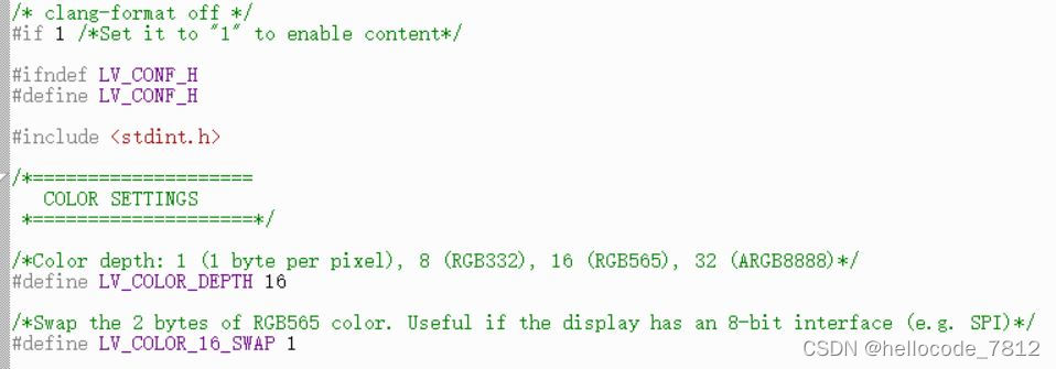
修改lv_conf.h中的条件编译,将#if 0改为#if 1,启用lv_conf.h文件,且调整屏幕的颜色设置,如下图所示:
同理打开lv_port_disp.h和 lv_port_disp.c文件。并修改 lv_port_disp.c中一下几处地方:
/*********************
 *      DEFINES
 *********************/

#define MY_DISP_HOR_RES 240
#define MY_DISP_VER_RES 240    //屏幕尺寸

/**********************
 *   GLOBAL FUNCTIONS
 **********************/

void lv_port_disp_init(void)
{
    /*-------------------------
     * Initialize your display
     * -----------------------*/
    disp_init();

    /*-----------------------------
     * Create a buffer for drawing
     *----------------------------*/

    /**
     * LVGL requires a buffer where it internally draws the widgets.
     * Later this buffer will passed to your display driver's `flush_cb` to copy its content to your display.
     * The buffer has to be greater than 1 display row
     *
     * There are 3 buffering configurations:
     * 1. Create ONE buffer:
     *      LVGL will draw the display's content here and writes it to your display
     *
     * 2. Create TWO buffer:
     *      LVGL will draw the display's content to a buffer and writes it your display.
     *      You should use DMA to write the buffer's content to the display.
     *      It will enable LVGL to draw the next part of the screen to the other buffer while
     *      the data is being sent form the first buffer. It makes rendering and flushing parallel.
     *
     * 3. Double buffering
     *      Set 2 screens sized buffers and set disp_drv.full_refresh = 1.
     *      This way LVGL will always provide the whole rendered screen in `flush_cb`
     *      and you only need to change the frame buffer's address.
     */

    /* Example for 1) */
    static lv_disp_draw_buf_t draw_buf_dsc_1;
    static lv_color_t buf_1[MY_DISP_HOR_RES * 10];                          /*A buffer for 10 rows*/
    lv_disp_draw_buf_init(&draw_buf_dsc_1, buf_1, NULL, MY_DISP_HOR_RES * 10);   /*Initialize the display buffer*/
#if 0
    /* Example for 2) */
    static lv_disp_draw_buf_t draw_buf_dsc_2;
    static lv_color_t buf_2_1[MY_DISP_HOR_RES * 10];                        /*A buffer for 10 rows*/
    static lv_color_t buf_2_2[MY_DISP_HOR_RES * 10];                        /*An other buffer for 10 rows*/
    lv_disp_draw_buf_init(&draw_buf_dsc_2, buf_2_1, buf_2_2, MY_DISP_HOR_RES * 10);   /*Initialize the display buffer*/

    /* Example for 3) also set disp_drv.full_refresh = 1 below*/
    static lv_disp_draw_buf_t draw_buf_dsc_3;
    static lv_color_t buf_3_1[MY_DISP_HOR_RES * MY_DISP_VER_RES];            /*A screen sized buffer*/
    static lv_color_t buf_3_2[MY_DISP_HOR_RES * MY_DISP_VER_RES];            /*Another screen sized buffer*/
    lv_disp_draw_buf_init(&draw_buf_dsc_3, buf_3_1, buf_3_2, MY_DISP_VER_RES * LV_VER_RES_MAX);   /*Initialize the display buffer*/
#endif
    /*-----------------------------------
     * Register the display in LVGL
     *----------------------------------*/

    static lv_disp_drv_t disp_drv;                         /*Descriptor of a display driver*/
    lv_disp_drv_init(&disp_drv);                    /*Basic initialization*/

    /*Set up the functions to access to your display*/

    /*Set the resolution of the display*/
    disp_drv.hor_res = 240;
    disp_drv.ver_res = 240;

    /*Used to copy the buffer's content to the display*/
    disp_drv.flush_cb = disp_flush;

    /*Set a display buffer*/
    disp_drv.draw_buf = &draw_buf_dsc_1;

    /*Required for Example 3)*/
    //disp_drv.full_refresh = 1

    /* Fill a memory array with a color if you have GPU.
     * Note that, in lv_conf.h you can enable GPUs that has built-in support in LVGL.
     * But if you have a different GPU you can use with this callback.*/
    //disp_drv.gpu_fill_cb = gpu_fill;

    /*Finally register the driver*/
    lv_disp_drv_register(&disp_drv);
}

/**********************
 *   STATIC FUNCTIONS
 **********************/

/*Initialize your display and the required peripherals.*/
static void disp_init(void)
{
    /*You code here*/
}

/*Flush the content of the internal buffer the specific area on the display
 *You can use DMA or any hardware acceleration to do this operation in the background but
 *'lv_disp_flush_ready()' has to be called when finished.*/
static void disp_flush(lv_disp_drv_t * disp_drv, const lv_area_t * area, lv_color_t * color_p)
{
    /*The most simple case (but also the slowest) to put all pixels to the screen one-by-one*/
#if 0
    int32_t x;
    int32_t y;
    for(y = area->y1; y <= area->y2; y++) {
        for(x = area->x1; x <= area->x2; x++) {
            /*Put a pixel to the display. For example:*/
            /*put_px(x, y, *color_p)*/
            color_p++;
        }
    }
#endif

	extern void LCD_Flush(lv_disp_drv_t * disp_drv,const lv_area_t * area, lv_color_t *color_p);
	LCD_Flush(disp_drv,area,color_p);
    /*IMPORTANT!!!
     *Inform the graphics library that you are ready with the flushing*/
    //lv_disp_flush_ready(disp_drv);
}注:移植lvgl库时有一个特殊报错,困扰我很久才解决,目前只是解决了,但不知原因是啥。
报错内容:CDK error: conflicting types for 'lv_group_set_editing'
解决办法:将报错所在位置的bool类型换成unsigned char类型即可,函数声明和函数实现都要改,如下:
void lv_group_set_editing(lv_group_t * group, unsigned char edit)2.4、编写main函数
#include "wm_include.h"
#include "wm_cpu.h"
#include "lcd.h"
#include "wm_timer.h"
#include "../lvgl/lvgl.h"
#include "../lvgl/lv_port_disp.h"
#include "lv_examples.h"

//通过SPI接口将图形输出到屏幕端
void LCD_Flush(lv_disp_drv_t * disp_drv,const lv_area_t * area, lv_color_t *color_p)
{
	tls_gpio_write(LCD_CS,FALSE); // Listen to us

	LCD_Address_Set(area->x1, area->y1, area->x2, area->y2);
	int32_t len = (area->x2 - area->x1 + 1) * (area->y2 - area->y1 + 1) * 2;

	S_WriteData((char*)color_p, len);

	tls_gpio_write(LCD_CS,true);
	lv_disp_flush_ready(disp_drv);         /* Indicate you are ready with the flushing*/
}

static void tick_timer_irq(u8 *arg)
{
	lv_tick_inc(1);
	// printf("timer irq\n");
}

int create_tick_timer(void)
{

	u8 timer_id;
	struct tls_timer_cfg timer_cfg;

	timer_cfg.unit = TLS_TIMER_UNIT_MS;
	timer_cfg.timeout = 1;
	timer_cfg.is_repeat = 1;
	timer_cfg.callback = (tls_timer_irq_callback)tick_timer_irq;
	timer_cfg.arg = NULL;
	timer_id = tls_timer_create(&timer_cfg);
	tls_timer_start(timer_id);
	// printf("timer start\n");

	return WM_SUCCESS;
}

void UserMain(void)
{
	tls_sys_clk_set(CPU_CLK_80M);//系统时钟

	LCD_Init(); //SPI驱动打开

	create_tick_timer();

	lv_init();
	lv_port_disp_init(); //LVGL初始化

	lv_example_meter_1(); //仪表示例1
    //lv_example_meter_2();    //可自行更换examples/widgets目录下的所有示例

	while(1){
		tls_os_time_delay(3);
		lv_task_handler();
	}
}
写在最后
国产芯片行业的崛起需要依赖市场的需求,需要每一个项目工程师的努力,时光不负赶路人,加油各位赶路人!