任务四 三层交换机实现不同VLAN间互访
信科上海分公司的财务部和客服部位于同一楼层,两个部门被划分在不同VLAN中,现在想通过三层交换机使这两个部门实现通信,网络拓扑图如下图。具体操作如下:

步骤1 规划交换机端口、VLAN及计算机IP地址,如上图文字所示。
步骤2 开启路由功能并划分VLAN10及VLAN20,分别加入端口f0/1和f0/2,代码如下:

Switch>en
Switch#conf t
Enter configuration commands, one per line.  End with CNTL/Z.
Switch(config)#
Switch(config)#ip routing       //启动路由功能
Switch(config)#vlan 10
Switch(config-vlan)#name AD
Switch(config-vlan)#ex
Switch(config)#vlan 20
Switch(config-vlan)#name FD
Switch(config-vlan)#ex
Switch(config)#int f0/1
Switch(config-if)#switch access vlan 10
Switch(config-if)#ex
Switch(config)#int f0/2
Switch(config-if)#switch access vlan 20
Switch(config-if)#ex
步骤3 为VLAN10及VLAN20设置IP地址,代码如下:


Switch(config)#int vlan 10
Switch(config-if)#
%LINK-5-CHANGED: Interface Vlan10, changed state to up

%LINEPROTO-5-UPDOWN: Line protocol on Interface Vlan10, changed state to up

Switch(config-if)#ip address 192.168.10.1 255.255.255.0       //设置vlan的ip地址
Switch(config-if)#no shutdown
Switch(config-if)#ex
Switch(config)#int vlan 20
Switch(config-if)#
%LINK-5-CHANGED: Interface Vlan20, changed state to up

%LINEPROTO-5-UPDOWN: Line protocol on Interface Vlan20, changed state to up

Switch(config-if)#ip address 192.168.20.1 255.255.255.0
Switch(config-if)#no shutdown
Switch(config-if)#ex
Switch(config)#ex
Switch#步骤3 验证互通性

任务五 交换机的RIP动态路由配置
当两台以上三层交换机级联时,为了使各交换机上连接的不同网段之间能够互相通信,就需要配置动态路由协议。常见的动态路由协议有RIP、OSPF等。本任务通过实现信科总部不同楼层之间的相互通信,介绍交换机的RIP动态路由配置。网络拓扑图如图所示。
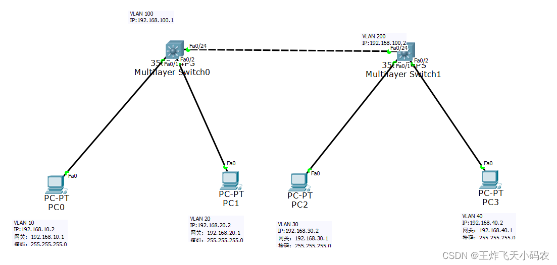
步骤1 在交换机S0和交换机S1上分别划分基于端口的VLAN

步骤2 配置交换机S0和S1各VLAN接口的IP地址

步骤3 设定PC1~PC4的网络位置及IP地址

步骤4 配置交换机S0,代码如下:
Switch>en
Switch#conf t
Enter configuration commands, one per line.  End with CNTL/Z.
Switch(config)#vlan 10
Switch(config-vlan)#ex
Switch(config)#vlan 20
Switch(config-vlan)#ex
Switch(config)#vlan 100
Switch(config-vlan)#ex
Switch(config)#int f0/1
Switch(config-if)#switch access vlan 10
Switch(config-if)#ex
Switch(config)#int f0/2
Switch(config-if)#switch access vlan 20
Switch(config-if)#int f0/24
Switch(config-if)#switch access vlan 100
Switch(config-if)#ex
Switch(config)#int vlan 10
Switch(config-if)#
%LINK-5-CHANGED: Interface Vlan10, changed state to up

%LINEPROTO-5-UPDOWN: Line protocol on Interface Vlan10, changed state to up

Switch(config-if)#ip add 192.168.10.1 255.255.255.0
Switch(config-if)#no shutdown
Switch(config-if)#ex
Switch(config)#int vlan 20
Switch(config-if)#
%LINK-5-CHANGED: Interface Vlan20, changed state to up

%LINEPROTO-5-UPDOWN: Line protocol on Interface Vlan20, changed state to up

Switch(config-if)#ip add 192.168.20.1 255.255.255.0
Switch(config-if)#no shutdown
Switch(config-if)#ex
Switch(config)#int vlan 100
Switch(config-if)#
%LINK-5-CHANGED: Interface Vlan100, changed state to up

%LINEPROTO-5-UPDOWN: Line protocol on Interface Vlan100, changed state to up

Switch(config-if)#ip add 192.168.100.1 255.255.255.0
Switch(config-if)#no shutdown
Switch(config-if)#ex
Switch(config)#ip routing
Switch(config)#
步骤5 配置交换机S1,代码如下:
Switch>en
Switch#conf t
Enter configuration commands, one per line.  End with CNTL/Z.
Switch(config)#vlan 30
Switch(config-vlan)#ex
Switch(config)#vlan 40
Switch(config-vlan)#ex
Switch(config)#vlan 200
Switch(config-vlan)#ex
Switch(config)#int f0/1
Switch(config-if)#switch access vlan 30
Switch(config-if)#ex
Switch(config)#int f0/2
Switch(config-if)#switch access vlan 40
Switch(config-if)#ex
Switch(config)#int f0/24
Switch(config-if)#switch access vlan 200
Switch(config-if)#ex
Switch(config)#int vlan 30
Switch(config-if)#
%LINK-5-CHANGED: Interface Vlan30, changed state to up

%LINEPROTO-5-UPDOWN: Line protocol on Interface Vlan30, changed state to up

Switch(config-if)#ip add 192.168.30.1 255.255.255.0
Switch(config-if)#no shutdown
Switch(config-if)#ex
Switch(config)#int vlan 40
Switch(config-if)#
%LINK-5-CHANGED: Interface Vlan40, changed state to up

%LINEPROTO-5-UPDOWN: Line protocol on Interface Vlan40, changed state to up

Switch(config-if)#ip add 192.168.40.1 255.255.255.0
Switch(config-if)#no shutdown
Switch(config-if)#ex
Switch(config)#int vlan 200
Switch(config-if)#
%LINK-5-CHANGED: Interface Vlan200, changed state to up

%LINEPROTO-5-UPDOWN: Line protocol on Interface Vlan200, changed state to up

Switch(config-if)#ip add 192.168.100.2 255.255.255.0
Switch(config-if)#no shutdown
Switch(config-if)#ex
Switch(config)#ip routing
Switch(config)# 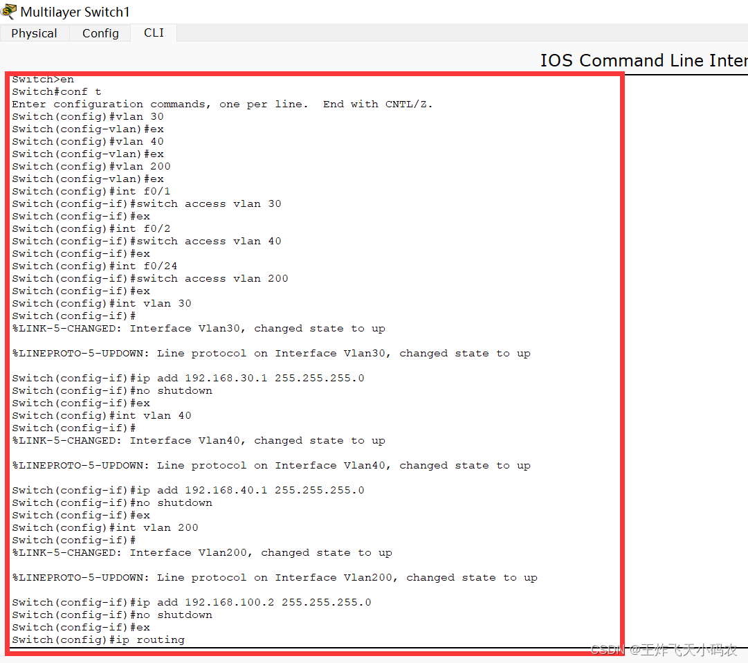
步骤6 通过Ping命令验证互通性

步骤7 在S0上添加直连网段的动态路由协议RIP

Switch>en
Switch#conf t
Enter configuration commands, one per line.  End with CNTL/Z.
Switch(config)#router rip
Switch(config-router)#network 192.168.10.0
Switch(config-router)#network 192.168.20.0
Switch(config-router)#network 192.168.100.0
Switch(config-router)#ex步骤8 在S1上添加直连网段的动态路由协议RIP,代码如下
Switch(config)#router rip
Switch(config-router)#network 192.168.30.0
Switch(config-router)#network 192.168.40.0
Switch(config-router)#network 192.168.100.0
Switch(config-router)#ex
步骤9 通过Ping命令验证互通性

任务六 交换机间OSPF动态路由配置
本任务通过利用OSPF协议实现信科公司不同楼层之间的相互通信,介绍交换机的OSPF动态路由配置,网络拓扑图如下图。

步骤1 参照本项目任务五步骤1~6,配置交换机S1、S2和PC1、PC2、PC3、PC4,并通过Ping命令验证互通性。
步骤2 在S0上启动OSPF协议,并将对应的直连网段配置到OSPF进程中,代码如下:
Switch#conf t
Enter configuration commands, one per line.  End with CNTL/Z.
Switch(config)#router ospf 1
Switch(config-router)#network 192.168.10.0 0.0.0.255 area 0
Switch(config-router)#network 192.168.20.0 0.0.0.255 area 0
Switch(config-router)#network 192.168.100.0 0.0.0.255 area 0
Switch(config-router)#ex
Switch(config)#步骤3 在S1上启动OSPF协议,并将对应的直连网段配置到OSPF进程中,代码如下:
Switch>en
Switch#conf t
Enter configuration commands, one per line.  End with CNTL/Z.
Switch(config)#router ospf 1
Switch(config-router)#network 192.168.30.0 255.255.255.0
% Incomplete command.
Switch(config-router)#network 192.168.30.0 0.0.0.255 area 0
Switch(config-router)#network 192.168.40.0 0.0.0.255 area 0
Switch(config-router)#network 192.168.100.0 0.0.0.255 area 0
Switch(config-router)#ex
Switch(config)#步骤4 通过Ping命令验证互通性
