关于本教程:
ESP32 基础篇
1.ESP32简介
2.ESP32 Arduino 集成开发环境
3.VS 代码和 PlatformIO
4.ESP32 引脚
5.ESP32 输入输出
6.ESP32 脉宽调制
7.ESP32 模拟输入
8.ESP32 中断定时器
9.ESP32 深度睡眠
ESP32 协议篇
1.ESP32 网络服务器 ☑
2.ESP32 LoRa
3.ESP32 BLE
4.ESP32 BLE 客户端-服务器
5.ESP32 蓝牙
6.ESP32 MQTT
7.ESP32 ESP-NOW
8.ESP32 Wi-Fi
9.ESP32 WebSocket
10.ESP32 ESP-MESH
11.ESP32 邮箱
12.ESP32 短信
13.ESP32 HTTP 获取 POST
14.HTTP GET Web APIs
15.HTTP POST Web APIs
ESP32 服务器篇
持续更新,关注博主不迷路!!!
ESP32 传感器模块篇
持续更新,关注博主不迷路!!!
ESP32 终极实战篇
百余项ESP32实战项目,敬请关注!!!
学习了ESP32基础篇之后,我们紧接着进入协议篇学习,这一部分我们将结合实例进一步学习ESP32。废话不多说,让我们开始吧!!!
ESP32 网络服务器——Arduino IDE
在此项目中,您将使用 Arduino IDE 编程环境创建一个带有 ESP32 的独立 Web 服务器,该服务器控制输出(两个 LED)。Web 服务器是移动响应的,可以使用任何设备作为本地网络上的浏览器进行访问。我们将逐步向您展示如何创建 Web 服务器以及代码如何工作。
项目概况
在直接进入项目之前,重要的是概述我们的 Web 服务器将做什么,以便以后更容易遵循这些步骤。
- 您将构建的 Web 服务器控制连接到 ESP32 的两个 LEDGPIO 26和GPIO 27;
- 您可以在本地网络中的浏览器中输入 ESP32 IP 地址来访问 ESP32 Web 服务器;
- 通过单击 Web 服务器上的按钮,您可以立即更改每个 LED 的状态。
所需零件
对于本教程,您需要以下部分:
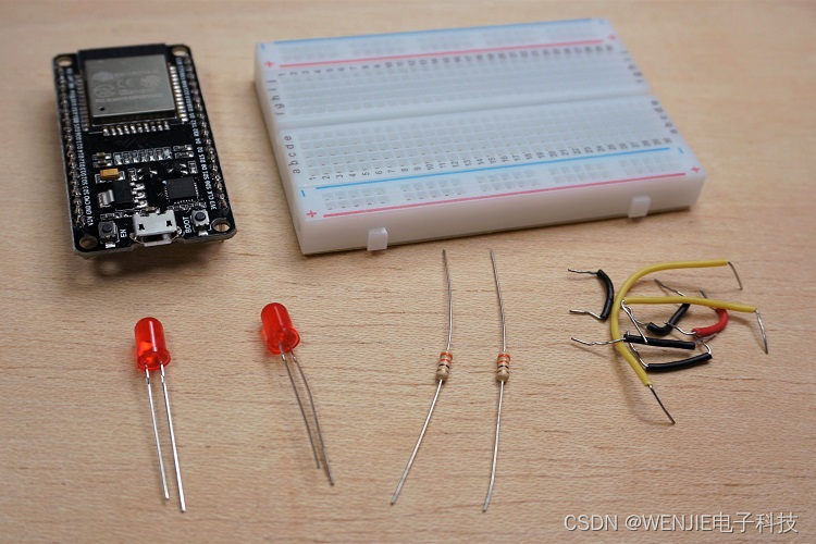
ESP32 开发板
2 个 5 毫米 LED
2x 330 欧姆电阻
面包板
跳线
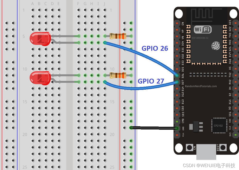
原理图
从构建电路开始。如下图所示将两个 LED 连接到 ESP32 – 一个 LED 连接到GPIO 26, 另一个到GPIO 27。
注意:我们使用的是带 36 个引脚的 ESP32 DEVKIT DOIT 板。在组装电路之前,请务必检查所用电路板的引出线。
ESP32 Web 服务器代码
我们在这里提供创建 ESP32 网络服务器的代码。将以下代码复制到您的 Arduino IDE,但先不要上传。您需要进行一些更改才能使其适合您。
#include <WiFi.h>

// Replace with your network credentials
const char* ssid1 = "";
const char* password1 = "";

// Set web server port number to 80
WiFiServer server(80);

// Variable to store the HTTP request
String header;

// Auxiliar variables to store the current output state
String output26State = "off";
String output27State = "off";

// Assign output variables to GPIO pins
const int output26 = 26;
const int output27 = 27;

// Current time
unsigned long currentTime = millis();
// Previous time
unsigned long previousTime = 0;
// Define timeout time in milliseconds (example: 2000ms = 2s)
const long timeoutTime = 2000;

void setup() {
  Serial.begin(115200);
  // Initialize the output variables as outputs
  pinMode(output26, OUTPUT);
  pinMode(output27, OUTPUT);
  // Set outputs to LOW
  digitalWrite(output26, LOW);
  digitalWrite(output27, LOW);

  // Connect to Wi-Fi network with SSID and password
  Serial.print("Connecting to ");
  Serial.println(ssid);
  WiFi.begin(ssid1, password1);
  while (WiFi.status() != WL_CONNECTED) {
    delay(500);
    Serial.print(".");
  }
  // Print local IP address and start web server
  Serial.println("");
  Serial.println("WiFi connected.");
  Serial.println("IP address: ");
  Serial.println(WiFi.localIP());
  server.begin();
}

void loop(){
  WiFiClient client = server.available();   // Listen for incoming clients

  if (client) {                             // If a new client connects,
    currentTime = millis();
    previousTime = currentTime;
    Serial.println("New Client.");          // print a message out in the serial port
    String currentLine = "";                // make a String to hold incoming data from the client
    while (client.connected() && currentTime - previousTime <= timeoutTime) {  // loop while the client's connected
      currentTime = millis();
      if (client.available()) {             // if there's bytes to read from the client,
        char c = client.read();             // read a byte, then
        Serial.write(c);                    // print it out the serial monitor
        header += c;
        if (c == '\n') {                    // if the byte is a newline character
          // if the current line is blank, you got two newline characters in a row.
          // that's the end of the client HTTP request, so send a response:
          if (currentLine.length() == 0) {
            // HTTP headers always start with a response code (e.g. HTTP/1.1 200 OK)
            // and a content-type so the client knows what's coming, then a blank line:
            client.println("HTTP/1.1 200 OK");
            client.println("Content-type:text/html");
            client.println("Connection: close");
            client.println();

            // turns the GPIOs on and off
            if (header.indexOf("GET /26/on") >= 0) {
              Serial.println("GPIO 26 on");
              output26State = "on";
              digitalWrite(output26, HIGH);
            } else if (header.indexOf("GET /26/off") >= 0) {
              Serial.println("GPIO 26 off");
              output26State = "off";
              digitalWrite(output26, LOW);
            } else if (header.indexOf("GET /27/on") >= 0) {
              Serial.println("GPIO 27 on");
              output27State = "on";
              digitalWrite(output27, HIGH);
            } else if (header.indexOf("GET /27/off") >= 0) {
              Serial.println("GPIO 27 off");
              output27State = "off";
              digitalWrite(output27, LOW);
            }

            // Display the HTML web page
            client.println("<!DOCTYPE html><html>");
            client.println("<head><meta name=\"viewport\" content=\"width=device-width, initial-scale=1\">");
            client.println("<link rel=\"icon\" href=\"data:,\">");
            // CSS to style the on/off buttons
            // Feel free to change the background-color and font-size attributes to fit your preferences
            client.println("<style>html { font-family: Helvetica; display: inline-block; margin: 0px auto; text-align: center;}");
            client.println(".button { background-color: #4CAF50; border: none; color: white; padding: 16px 40px;");
            client.println("text-decoration: none; font-size: 30px; margin: 2px; cursor: pointer;}");
            client.println(".button2 {background-color: #555555;}</style></head>");

            // Web Page Heading
            client.println("<body><h1>ESP32 Web Server</h1>");

            // Display current state, and ON/OFF buttons for GPIO 26
            client.println("<p>GPIO 26 - State " + output26State + "</p>");
            // If the output26State is off, it displays the ON button
            if (output26State=="off") {
              client.println("<p><a href=\"/26/on\"><button class=\"button\">ON</button></a></p>");
            } else {
              client.println("<p><a href=\"/26/off\"><button class=\"button button2\">OFF</button></a></p>");
            }

            // Display current state, and ON/OFF buttons for GPIO 27
            client.println("<p>GPIO 27 - State " + output27State + "</p>");
            // If the output27State is off, it displays the ON button
            if (output27State=="off") {
              client.println("<p><a href=\"/27/on\"><button class=\"button\">ON</button></a></p>");
            } else {
              client.println("<p><a href=\"/27/off\"><button class=\"button button2\">OFF</button></a></p>");
            }
            client.println("</body></html>");

            // The HTTP response ends with another blank line
            client.println();
            // Break out of the while loop
            break;
          } else { // if you got a newline, then clear currentLine
            currentLine = "";
          }
        } else if (c != '\r') {  // if you got anything else but a carriage return character,
          currentLine += c;      // add it to the end of the currentLine
        }
      }
    }
    // Clear the header variable
    header = "";
    // Close the connection
    client.stop();
    Serial.println("Client disconnected.");
    Serial.println("");
  }
}
设置您的WiFi网络
您需要使用您的网络修改以下行:SSID 和密码。该代码对您应该在何处进行更改进行了很好的注释。
// Replace with your network credentials
const char* ssid1     = "";
const char* password1 = "";
上传代码
现在,您可以上传代码,Web 服务器将立即运行。按照以下步骤将代码上传到 ESP32:
1)将 ESP32 开发板插入电脑;
2) 在 Arduino IDE 的工具>开发板中选择您的开发板 (在我们的例子中,我们使用的是 ESP32 DEVKIT DOIT 开发板);

3) 在工具> 端口中选择 COM 端口 。
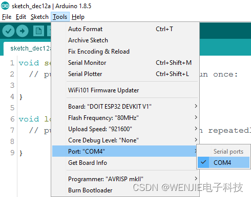
4) 按Arduino IDE 中的上传按钮,等待几秒钟,同时代码编译并上传到您的电路板。

5) 等待“上传完成”消息。

查找 ESP IP 地址
上传代码后,以115200的波特率打开Serial Monitor。

按下 ESP32 EN 按钮(重置)。ESP32 连接 Wi-Fi,并在串口监视器上输出 ESP IP 地址。复制该 IP 地址,因为您需要它来访问 ESP32 网络服务器。

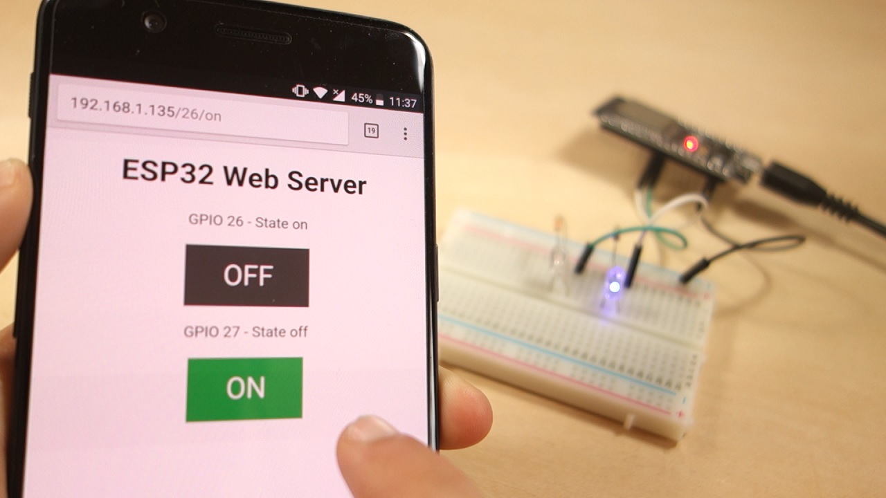
访问网络服务器
要访问 Web 服务器,请打开浏览器,粘贴 ESP32 IP 地址,您将看到以下页面。在我们的例子中是192.168.1.135。
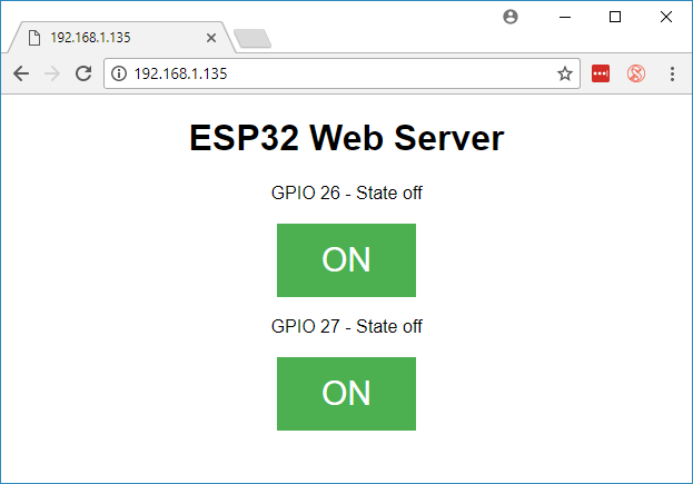
如果你看一下串行监视器,你可以看到后台发生了什么。ESP 收到来自新客户端(在本例中为您的浏览器)的 HTTP 请求。
测试网络服务器
现在您可以测试您的网络服务器是否正常工作。单击按钮以控制 LED。
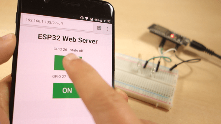
同时,你可以看一下Serial Monitor,看看后台发生了什么。例如,当您单击按钮以打开GPIO 26ON,ESP32 在/26/on URL上收到请求。

当 ESP32 收到该请求时,它会打开连接到GPIO 26ON 并在网页上更新其状态。

该按钮用于GPIO 27以类似的方式工作。测试它是否正常工作。
代码如何运作
在本节中,将仔细查看代码以了解其工作原理。
您需要做的第一件事是包含 WiFi 库。
#include <WiFi.h>如前所述,您需要在双引号内的以下行中插入您的 ssid 和密码。
const char* ssid1 = "";
const char* password1 = "";
然后,将 Web 服务器设置为端口 80。
WiFiServer server(80);以下行创建一个变量来存储 HTTP 请求的标头:
String header;接下来,您创建辅助变量来存储输出的当前状态。如果要添加更多输出并保存其状态,则需要创建更多变量。
String output26State = "off";
String output27State = "off";
您还需要为每个输出分配一个 GPIO。这里我们使用GPIO 26和GPIO 27. 您可以使用任何其他合适的 GPIO。
const int output26 = 26;
const int output27 = 27;
setup()
现在,让我们进入setup(). 首先,我们以 115200 的波特率启动串行通信以进行调试。
Serial.begin(115200);您还可以将 GPIO 定义为输出并将它们设置为低电平。
// Initialize the output variables as outputs
pinMode(output26, OUTPUT);
pinMode(output27, OUTPUT);

// Set outputs to LOW
digitalWrite(output26, LOW);
digitalWrite(output27, LOW);
以下几行开始 Wi-Fi 连接WiFi.begin(ssid, password), 等待连接成功并在串行监视器中打印 ESP IP 地址。
// Connect to Wi-Fi network with SSID and password
Serial.print("Connecting to ");
Serial.println(ssid);
WiFi.begin(ssid, password);
while (WiFi.status() != WL_CONNECTED) {
  delay(500);
  Serial.print(".");
}
// Print local IP address and start web server
Serial.println("");
Serial.println("WiFi connected.");
Serial.println("IP address: ");
Serial.println(WiFi.localIP());
server.begin();
loop()
在里面loop()我们对新客户端与 Web 服务器建立连接时发生的情况进行编程。
ESP32 始终通过以下行侦听传入的客户端:
WiFiClient client = server.available(); // Listen for incoming clients当收到来自客户端的请求时,我们将保存传入的数据。只要客户端保持连接,后面的 while 循环就会运行。我们不建议更改代码的以下部分,除非您确切地知道自己在做什么。
if (client) { // If a new client connects,
  Serial.println("New Client."); // print a message out in the serial port
  String currentLine = ""; // make a String to hold incoming data from the client
  while (client.connected()) { // loop while the client's connected
    if (client.available()) { // if there's bytes to read from the client,
      char c = client.read(); // read a byte, then
      Serial.write(c); // print it out the serial monitor
      header += c;
      if (c == '\n') { // if the byte is a newline character
      // if the current line is blank, you got two newline characters in a row.
      / that's the end of the client HTTP request, so send a response:
        if (currentLine.length() == 0) {
        // HTTP headers always start with a response code (e.g. HTTP/1.1 200 OK)
        // and a content-type so the client knows what's coming, then a blank line:
          client.println("HTTP/1.1 200 OK");
          client.println("Content-type:text/html");
          client.println("Connection: close");
          client.println();
if 和 else 语句的下一部分检查在您的网页中按下了哪个按钮,并相应地控制输出。正如我们之前所见,我们根据按下的按钮向不同的 URL 发出请求。
// turns the GPIOs on and off
if (header.indexOf("GET /26/on") >= 0) {
  Serial.println("GPIO 26 on");
  output26State = "on";
  digitalWrite(output26, HIGH);
} else if (header.indexOf("GET /26/off") >= 0) {
  Serial.println("GPIO 26 off");
  output26State = "off";
  digitalWrite(output26, LOW);
} else if (header.indexOf("GET /27/on") >= 0) {
  Serial.println("GPIO 27 on");
  output27State = "on";
  digitalWrite(output27, HIGH);
} else if (header.indexOf("GET /27/off") >= 0) {
  Serial.println("GPIO 27 off");
  output27State = "off";
  digitalWrite(output27, LOW);
}
例如,如果您按下 GPIO 26 ON 按钮,ESP32 会收到一个关于/26/ON URL 的请求(我们可以在串行监视器的 HTTP 标头上看到该信息)。因此,我们可以检查标头是否包含表达式GET /26/on。如果它包含,我们改变output26State变量为 ON,ESP32 打开 LED。
这对其他按钮的作用类似。所以,如果你想添加更多输出,你应该修改这部分代码以包含它们。
显示 HTML 网页
您需要做的下一件事是创建网页。ESP32 将使用一些 HTML 代码向您的浏览器发送响应以构建网页。
使用此表达式将网页发送到客户端client.println(). 您应该输入要作为参数发送给客户端的内容。
我们应该发送的第一件事始终是以下行,这表明我们正在发送 HTML。
<!DOCTYPE HTML><html>下面是用来防止对图标的请求。– 你不需要担心这条线。
client.println("<link rel=\"icon\" href=\"data:,\">");网页样式
接下来,我们有一些 CSS 文本来设置按钮和网页外观的样式。我们选择 Helvetica 字体,将要显示的内容定义为块并居中对齐。
client.println("<style>html { font-family: Helvetica; display: inline-block; margin: 0px auto; text-align: center;}");我们使用 #4CAF50 颜色为按钮设置样式,无边框,白色文本,并使用此填充:16px 40px。我们还将 text-decoration 设置为 none,将字体大小、边距和光标定义为指针。
client.println(".button { background-color: #4CAF50; border: none; color: white; padding: 16px 40px;");
client.println("text-decoration: none; font-size: 30px; margin: 2px; cursor: pointer;}");
我们还定义了第二个按钮的样式,具有我们之前定义的按钮的所有属性,但颜色不同。这将是关闭按钮的样式。
client.println(".button2 {background-color: #555555;}</style></head>");设置网页第一标题
在下一行中,您可以设置网页的第一个标题。这里我们有“ ESP32 Web Server ”,但你可以将这个文本更改为你喜欢的任何内容。
// Web Page Heading
client.println("<h1>ESP32 Web Server</h1>");
显示按钮和相应的状态
然后,你写一个段落来显示GPIO 26当前状态。如您所见,我们使用output26State变量,以便在该变量更改时立即更新状态。
client.println("<p>GPIO 26 - State " + output26State + "</p>");然后,我们根据 GPIO 的当前状态显示开或关按钮。如果 GPIO 的当前状态为关闭,我们显示 ON 按钮,如果不是,我们显示 OFF 按钮。
if (output26State=="off") {
  client.println("<p><a href=\"/26/on\"><button class=\"button\">ON</button></a></p>");
} else {
  client.println("<p><a href=\"/26/off\"><button class=\"button button2\">OFF</button></a></p>");
}我们使用相同的程序GPIO 27.
关闭连接
最后,当响应结束时,我们清除header变量,并停止与客户端的连接client.stop().
// Clear the header variable
header = "";
// Close the connection
client.stop();
总结
在本教程中,我们向您展示了如何使用 ESP32 构建网络服务器。我们已经向您展示了一个控制两个 LED 的简单示例,但我们的想法是用继电器或您想要控制的任何其他输出替换这些 LED。