目录
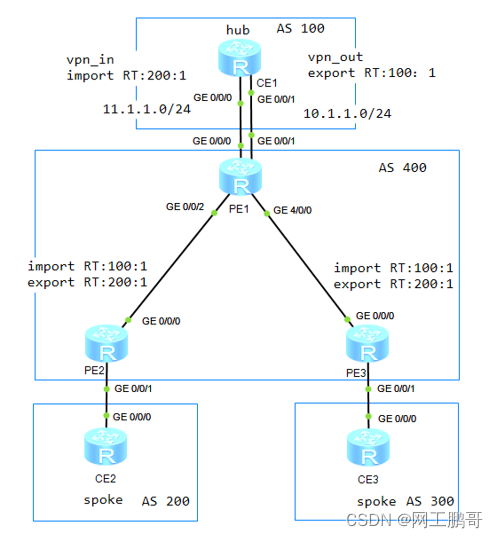
1.实验环境:如图所示,CE1为某公司的总部,CE2、CE3为某公司的分部,现在要求总部和分部之间通过mpls vpn实现私网的互访,并且要求分部之间互访的流量必须经过总部。
1)配置ip地址,ip规划见表。(接口属于vpn实例的ip地址步骤4再配置)
3)配置ISP内部的mpls及mpls ldp,建立公网的lsp隧道
6)配置spoke PE和hub PE之间的MP-BGP邻居关系
1.实验环境:如图所示,CE1为某公司的总部,CE2、CE3为某公司的分部,现在要求总部和分部之间通过mpls vpn实现私网的互访,并且要求分部之间互访的流量必须经过总部。
(1)AS400为ISP网络,其中IGP协议使用ospf;
(2)CE和PE之间运行BGP协议
2.实验目的:
①掌握hub and spoke的基本配置
②掌握hub and spoke的工作原理
3.实验拓扑:
MPLS VPN基本组网-hub and spoke实验拓扑如图所示。
4.实验步骤:
1)配置ip地址,ip规划见表。(接口属于vpn实例的ip地址步骤4再配置)
mpls vpn基本组网-hub and spoke ip地址规划表
| 设备名称 |
接口编号 |
Ip地址 |
所属Vpn实例 |
| PE1 |
G0/0/0 |
11.1.1.1/24 |
vpn_in |
| PE1 |
G0/0/1 |
10.1.1.1/24 |
vpn_out |
| PE1 |
G0/0/2 |
10.0.12.1/24 |
|
| PE1 |
G4/0/0 |
10.0.13.1/24 |
|
| PE1 |
Loopback 0 |
1.1.1.1/32 |
|
| PE2 |
G0/0/0 |
10.0.12.2/24 |
|
| PE2 |
G0/0/1 |
22.1.1.1/24 |
vpn1 |
| PE2 |
Loopback 0 |
2.2.2.2/32 |
|
| PE3 |
G0/0/0 |
10.0.13.2/24 |
|
| PE3 |
G0/0/1 |
33.1.1.1/24 |
vpn1 |
| PE3 |
Loopback 0 |
3.3.3.3/32 |
|
| CE1 |
G0/0/0 |
11.1.1.2/24 |
|
| CE1 |
G0/0/1 |
10.1.1.2/24 |
|
| CE1 |
Loopback 0 |
10.10.10.10/32 |
|
| CE2 |
G0/0/0 |
22.1.1.2/24 |
|
| CE2 |
Loopback 0 |
20.20.20.20/32 |
|
| CE3 |
G0/0/0 |
33.1.1.2/24 |
|
| CE3 |
Loopback 0 |
30.30.30.30/32 |
2)配置ISP网络的IGP协议
PE1的配置:
[PE1]ospf

[PE1-ospf-1]area  0

[PE1-ospf-1-area-0.0.0.0]network  10.0.12.0 0.0.0.255

[PE1-ospf-1-area-0.0.0.0]network  10.0.13.0 0.0.0.255

[PE1-ospf-1-area-0.0.0.0]network  1.1.1.1 0.0.0.0
PE2的配置:
[PE2]ospf

[PE2-ospf-1]area  0

[PE2-ospf-1-area-0.0.0.0]network  10.0.12.0 0.0.0.255

[PE2-ospf-1-area-0.0.0.0]network  2.2.2.2 0.0.0.0
PE3的配置:
[PE3]ospf

[PE3-ospf-1]area 0

[PE3-ospf-1-area-0.0.0.0]network  10.0.13.0 0.0.0.255

[PE3-ospf-1-area-0.0.0.0]network 3.3.3.3 0.0.0.0
查看PE1的路由表
[PE1]display ip routing-table

Route Flags: R - relay, D - download to fib

------------------------------------------------------------------------------

Routing Tables: Public

         Destinations : 13       Routes : 13


Destination/Mask    Proto   Pre  Cost      Flags NextHop         Interface


        1.1.1.1/32  Direct  0    0           D   127.0.0.1       LoopBack0

        2.2.2.2/32  OSPF    10   1           D   10.0.12.2       GigabitEthernet0/0/2

        3.3.3.3/32  OSPF    10   1           D   10.0.13.2       GigabitEthernet4/0/0

      10.0.12.0/24  Direct  0    0           D   10.0.12.1       GigabitEthernet0/0/2

      10.0.12.1/32  Direct  0    0           D   127.0.0.1       GigabitEthernet0/0/2

    10.0.12.255/32  Direct  0    0           D   127.0.0.1       GigabitEthernet0/0/2

      10.0.13.0/24  Direct  0    0           D   10.0.13.1       GigabitEthernet4/0/0

      10.0.13.1/32  Direct  0    0           D   127.0.0.1       GigabitEthernet4/0/0

    10.0.13.255/32  Direct  0    0           D   127.0.0.1       GigabitEthernet4/0/0

      127.0.0.0/8   Direct  0    0           D   127.0.0.1       InLoopBack0

      127.0.0.1/32  Direct  0    0           D   127.0.0.1       InLoopBack0

127.255.255.255/32  Direct  0    0           D   127.0.0.1       InLoopBack0

255.255.255.255/32  Direct  0    0           D   127.0.0.1       InLoopBack0
可以看到能够学习到PE2和PE3的环回口路由。
3)配置ISP内部的mpls及mpls ldp,建立公网的lsp隧道
PE1的配置:
[PE1]mpls lsr-id 1.1.1.1

[PE1]mpls

[PE1-mpls]q

[PE1]mpls ldp

[PE1]interface  g0/0/2

[PE1-GigabitEthernet0/0/2]mpls

[PE1-GigabitEthernet0/0/2]mpls  ldp

[PE1-GigabitEthernet0/0/2]q

[PE1]interface  g4/0/0

[PE1-GigabitEthernet4/0/0]mpls

[PE1-GigabitEthernet4/0/0]mpls  ldp
PE2的配置:
[PE2]mpls  lsr-id 2.2.2.2

[PE2]mpls

[PE2-mpls]q

[PE2]mpls ldp

[PE2]interface  g0/0/0

[PE2-GigabitEthernet0/0/0]mpls

[PE2-GigabitEthernet0/0/0]mpls  ldp
PE3的配置
[PE3]mpls  lsr-id  3.3.3.3

[PE3]mpls

[PE3-mpls]q

[PE3]mpls ldp

[PE3]interface  g0/0/0

[PE3-GigabitEthernet0/0/0]mpls

[PE3-GigabitEthernet0/0/0]mpls ldp
查看mpls lsp的建立情况
[PE1]display mpls lsp

-------------------------------------------------------------------------------

                 LSP Information: LDP LSP

-------------------------------------------------------------------------------

FEC                In/Out Label  In/Out IF                      Vrf Name

2.2.2.2/32         NULL/3        -/GE0/0/2

2.2.2.2/32         1024/3        -/GE0/0/2

1.1.1.1/32         3/NULL        -/-

3.3.3.3/32         NULL/3        -/GE4/0/0

3.3.3.3/32         1025/3        -/GE4/0/0
4)配置vpn实例,将接口加入到vpn实例。
PE1的配置:
[PE1]ip vpn-instance  vpn_in //创建vpn实例vpn_in,用于接收分部的路由

[PE1-vpn-instance-vpn_in]route-distinguisher 100:1

[PE1-vpn-instance-vpn_in-af-ipv4]vpn-target 200:1 import-extcommunity //配置入RT为200:1

[PE1]ip vpn-instance vpn_out//创建vpn实例vpn_in,用于发送路由

[PE1-vpn-instance-vpn_out]route-distinguisher 100:2

[PE1-vpn-instance-vpn_out-af-ipv4]vpn-target 100:1 export-extcommunity//配置出RT为100:1

[PE1]int g0/0/0

[PE1-GigabitEthernet0/0/0]ip binding  vpn-instance vpn_in //将G0/0/0接口绑定到实例vpn_in

[PE1-GigabitEthernet0/0/0]ip address  11.1.1.1 24

[PE1]interface  g0/0/1

[PE1-GigabitEthernet0/0/1]ip binding vpn-instance vpn_out/将G0/0/1接口绑定到实例vpn_out

[PE1-GigabitEthernet0/0/1]ip address  10.1.1.1 24
PE2的配置:
[PE2]ip vpn-instance vpn1

[PE2-vpn-instance-vpn1]route-distinguisher 200:1

[PE2-vpn-instance-vpn1-af-ipv4]vpn-target 100:1 import-extcommunity //配置入RT为100:1,此处需要与hub节点的PE中的vpn_out的对应

[PE2-vpn-instance-vpn1-af-ipv4]vpn-target 200:1 export-extcommunity//配置出RT为200:1,此处需要与hub节点的PE中的vpn_in的对应

[PE2]interface  g0/0/1

[PE2-GigabitEthernet0/0/1]ip binding  vpn-instance vpn1

[PE2-GigabitEthernet0/0/1]ip address  22.1.1.1 24
PE3的配置:
[PE3]ip vpn-instance vpn1

[PE3-vpn-instance-vpn1]route-distinguisher 300:1

[PE3-vpn-instance-vpn1-af-ipv4]vpn-target 200:1 export-extcommunity //配置入RT为100:1,此处需要与hub节点的PE中的vpn_out的对应

[PE3-vpn-instance-vpn1-af-ipv4]vpn-target 100:1 import-extcommunity//配置出RT为200:1,此处需要与hub节点的PE中的vpn_in的对应

[PE3]interface  g0/0/1

[PE3-GigabitEthernet0/0/1]ip binding  vpn-instance vpn1

[PE3-GigabitEthernet0/0/1]ip address  33.1.1.1 24
此处的RT值的配置规则为:
Spoke PE的入RT必须与hub PE的vpn_out相同,spoke PE的出RT必须与hub PE的vpn_in相同。hub PE的vpn_in用于接收spoke路由给hub节点,hub PE的vpn_out用于接收hub节点的路由,然后再发布给spoke PE。
5)配置PE和CE的BGP路由协议
CE1的配置:
[CE1]bgp 100

[CE1-bgp]peer  11.1.1.1 as-number 400

[CE1-bgp]peer  10.1.1.1 as-number 400

[CE1-bgp]network  10.10.10.10 32
PE1的配置:
[PE1]bgp  400

[PE1-bgp]ipv4-family vpnv4

[PE1-bgp]ipv4-family vpn-instance vpn_in

[PE1-bgp-vpn_in]peer  11.1.1.2 as-number 100

[PE1-bgp-vpn_in]q

[PE1-bgp]ipv4-family vpn-instance vpn_out

[PE1-bgp-vpn_out]peer 10.1.1.2 as-number 100
查看PE1的bgp邻居关系
[PE1]display  bgp  vpnv4 all  peer


 BGP local router ID : 10.0.12.1

 Local AS number : 400

 Total number of peers : 2                Peers in established state : 2


  Peer            V          AS  MsgRcvd  MsgSent  OutQ  Up/Down       State PrefRcv

  Peer of IPv4-family for vpn instance :


 VPN-Instance vpn_in, Router ID 10.0.12.1:

  11.1.1.2        4         100        4        3     0 00:01:31 Established       1


 VPN-Instance vpn_out, Router ID 10.0.12.1:

  10.1.1.2        4         100        4        3     0 00:01:19 Established       1
显示结果为PE1分别通过vpn_in和vpn_out与11.1.1.2、10.1.1.2建立了BGP邻居关系。
CE2的配置:
[CE2]bgp  200

[CE2-bgp]peer  22.1.1.1 as-number  400

[CE2-bgp]network  20.20.20.20 32
PE2的配置:
[PE2]bgp  400

[PE2-bgp]ipv4-family vpn-instance vpn1

[PE2-bgp-vpn1]peer  22.1.1.2 as-number 200
查看PE2的BGP邻居
[PE2]display bgp  vpnv4 all  peer


 BGP local router ID : 10.0.12.2

 Local AS number : 400

 Total number of peers : 1                Peers in established state : 1


  Peer            V          AS  MsgRcvd  MsgSent  OutQ  Up/Down       State PrefRcv


  Peer of IPv4-family for vpn instance :


 VPN-Instance vpn1, Router ID 10.0.12.2:

  22.1.1.2        4         200        5        4     0 00:02:36 Established       1
CE3的配置:
[CE3]bgp 300

[CE3-bgp]peer 33.1.1.1 as-number 400

[CE3-bgp]network 30.30.30.30 32
PE3的配置:
[PE3]bgp  400

[PE3-bgp]ipv4-family vpn-instance vpn1

[PE3-bgp-vpn1]peer  33.1.1.2 as-number 300
查看PE3的bgp邻居
[PE3]display bgp vpnv4 all peer


 BGP local router ID : 10.0.13.2

 Local AS number : 400

 Total number of peers : 1                Peers in established state : 1


  Peer            V          AS  MsgRcvd  MsgSent  OutQ  Up/Down       State PrefRcv


  Peer of IPv4-family for vpn instance :


 VPN-Instance vpn1, Router ID 10.0.13.2:

  33.1.1.2        4         300        4        3     0 00:01:17 Established       1
6)配置spoke PE和hub PE之间的MP-BGP邻居关系
PE1的配置:
[PE1]bgp  400

[PE1-bgp]peer 2.2.2.2 as-number 400

[PE1-bgp]peer 2.2.2.2 connect-interface LoopBack 0

[PE1-bgp]peer 3.3.3.3 as-number 400

[PE1-bgp]peer 3.3.3.3 connect-interface LoopBack 0

[PE1-bgp]ipv4-family vpnv4

[PE1-bgp-af-vpnv4]peer 2.2.2.2 enable

[PE1-bgp-af-vpnv4]peer 3.3.3.3 enable
PE2的配置:
[PE2]bgp  400

[PE2-bgp]peer  1.1.1.1 as-number 400

[PE2-bgp]peer  1.1.1.1 connect-interface LoopBack 0

[PE2-bgp]ipv4-family vpnv4

[PE2-bgp-af-vpnv4]peer  1.1.1.1 enable
PE3的配置:
[PE3]bgp 400

[PE3-bgp] peer 1.1.1.1 as-number 400

[PE3-bgp] peer 1.1.1.1 connect-interface LoopBack0

[PE3-bgp] ipv4-family vpnv4

[PE3-bgp-af-vpnv4] peer 1.1.1.1 enable
查看PE1的vpnv4邻居关系
[PE1]display bgp vpnv4 all peer


 BGP local router ID : 10.0.12.1

 Local AS number : 400

 Total number of peers : 4                Peers in established state : 4


  Peer            V          AS  MsgRcvd  MsgSent  OutQ  Up/Down       State PrefRcv


  2.2.2.2         4         400        3        5     0 00:00:47 Established       1

  3.3.3.3         4         400        3        7     0 00:00:03 Established       1


  Peer of IPv4-family for vpn instance :


 VPN-Instance vpn_in, Router ID 10.0.12.1:

  11.1.1.2        4         100       23       22     0 00:18:48 Established       1


 VPN-Instance vpn_out, Router ID 10.0.12.1:

  10.1.1.2        4         100       23       20     0 00:18:36 Established       1
结果表示PE1分别和PE2(2.2.2.2)、PE3(3.3.3.3)建立了mp-bgp的邻居关系。
查看PE1的vpnv4路由表
[PE1]display bgp vpnv4 all peer


 BGP local router ID : 10.0.12.1

 Local AS number : 400

 Total number of peers : 4                Peers in established state : 4


  Peer            V          AS  MsgRcvd  MsgSent  OutQ  Up/Down       State PrefRcv


  2.2.2.2         4         400        3        5     0 00:00:47 Established       1

  3.3.3.3         4         400        3        7     0 00:00:03 Established       1


  Peer of IPv4-family for vpn instance :


 VPN-Instance vpn_in, Router ID 10.0.12.1:

  11.1.1.2        4         100       23       22     0 00:18:48 Established       1


 VPN-Instance vpn_out, Router ID 10.0.12.1:

  10.1.1.2        4         100       23       20     0 00:18:36 Established       1
结果表明,再vpn_in的路由中,可以看到学习到了各个CE节点的路由信息,但是vpn_out的路由中,并没有学习到spoke CE的路由信息。
思考:为什么vpn_out节点无法学习到spoke CE的路由信息?如何解决问题?
以路由从Spoke-CE2发布到Spoke-CE3为例,大体过程如下:
①Spoke-CE2通过EBGP将路由发布给Spoke-PE2。
②Spoke-PE2通过IBGP将该路由发布给Hub-PE1。
③Hub-PE1通过VPN实例(VPN_in)的Import Target属性将该路由引入VPN_in路由表,并通过EBGP发布给Hub-CE1。
④Hub-CE1通过EBGP连接学习到该路由,并通过另一个EBGP连接将该路由发布给Hub-PE1的VPN实例(VPN_out)。
⑤Hub-PE1发布携带VPN_out的Export Target属性的路由给所有Spoke-PE。
⑥Spoke-PE3通过EBGP将该路由发布给Spoke-CE3。
当执行到④时,20.20.20.20/32的路由的as-path属性为400 200,再次发送给PE1,由于PE1为AS400,基于BGP的防环规则,收到as-path属性包括本地的as号的路由时,将不接收路由。
因此在CE1上可以看到路由信息,但是PE1无法通过实例vpn_out学习到其他CE的路由信息。如下:
<CE1>display  bgp  routing-table


 BGP Local router ID is 11.1.1.2

 Status codes: * - valid, > - best, d - damped,

               h - history,  i - internal, s - suppressed, S - Stale

               Origin : i - IGP, e - EGP, ? - incomplete


 Total Number of Routes: 3

      Network            NextHop        MED        LocPrf    PrefVal Path/Ogn


 *>   10.10.10.10/32     0.0.0.0         0                     0      i

 *>   20.20.20.20/32     11.1.1.1                              0      400 200i

 *>   30.30.30.30/32     11.1.1.1                              0      400 300i
在PE1使用如下配置即可解决该问题:
PE1的配置:
[PE1]bgp 400

[PE1-bgp]ipv4-family vpn-instance vpn_out

[PE1-bgp-vpn_out]peer  10.1.1.2 allow-as-loop //配置从10.1.1.2收到路由时,能够与本地AS号的重复次数,缺省为1次
再次查看PE1的bgp 实例vpn_out路由表
[PE1]display bgp vpnv4 vpn-instance vpn_out routing-table


 BGP Local router ID is 10.0.12.1

 Status codes: * - valid, > - best, d - damped,

               h - history,  i - internal, s - suppressed, S - Stale

               Origin : i - IGP, e - EGP, ? - incomplete


 VPN-Instance vpn_out, Router ID 10.0.12.1:


 Total Number of Routes: 3

      Network            NextHop        MED        LocPrf    PrefVal Path/Ogn


 *>   10.10.10.10/32     10.1.1.2        0                     0      100i

 *>   20.20.20.20/32     10.1.1.2                              0      100 400 200i

 *>   30.30.30.30/32     10.1.1.2                              0      100 400 300i
此时PE1的vpn_out能够学习到spoke ce发布的路由信息。
查看CE2的BGP路由表
<CE2>display  bgp  routing-table


 BGP Local router ID is 22.1.1.2

 Status codes: * - valid, > - best, d - damped,

               h - history,  i - internal, s - suppressed, S - Stale

               Origin : i - IGP, e - EGP, ? - incomplete


 Total Number of Routes: 3

      Network            NextHop        MED        LocPrf    PrefVal Path/Ogn


 *>   10.10.10.10/32     22.1.1.1                              0      400 100i

 *>   20.20.20.20/32     0.0.0.0         0                     0      i

 *>   30.30.30.30/32     22.1.1.1                              0      400 100 400 300i
结果表明,用于hub节点10.10.10.10/32的路由,也拥有spoke节点30.30.30.30/32的路由,不过as-path为400 100 400 300,说明去往spoke节点,需要经过hub节点转发。
测试CE2去往CE3的流量路径
<CE2>tracert -a 20.20.20.20 30.30.30.30

 traceroute to  30.30.30.30(30.30.30.30), max hops: 30 ,packet length: 40,press CTRL_C to break

 1 22.1.1.1 30 ms  20 ms  10 ms

 2 10.1.1.1 30 ms  30 ms  30 ms

 3 10.1.1.2 40 ms  40 ms  30 ms

 4 11.1.1.1 40 ms  40 ms  40 ms

 5 33.1.1.1 50 ms  60 ms  50 ms

 6 33.1.1.2 50 ms  60 ms  50 ms
结果表明,流量路径为CE2-PE2-PE1-CE1-PE1-PE3-CE3。Spoke节点互访的数据都将经过hub节点,能够更加方便流量信息的管控。