本文紧接着上一篇文章:《解析百度Apollo之决策规划模块》。会详细讲解决策规划模块中是如何生成参考线和行车轨迹供车辆行驶的。参考线和轨迹直接影响了自动驾驶车辆对于方向和速度的控制,因此,说它是自动驾驶系统中最重要的数据都不为过。
前言
本文是百度自动驾驶平台Apollo项目系列文章中的一篇,会讲解Planning模块中的参考线逻辑。
对于刚接触Apollo项目的读者可以阅读我博客中的另外一篇文章 - 《解析百度Apollo自动驾驶平台》,那里对Apollo项目做了整体的介绍。
ReferenceLine(参考线)与Routing模块和Planning模块都相关。因此本文假定读者已经对这两个模块有一定了解。如果没有,建议读者先阅读下面两篇文章:
本文以Apollo项目2019年初的版本为基础进行讲解。
- 版本:3.5
- 获取代码时间:2019年2月7日
介绍
我们先介绍一下参考线在整个Planning模块中所处的位置:
决策规划模块负责生成车辆的行驶轨迹。要做到这一点,决策规划模块需要从宏观到局部经过三个层次来进行决策。
- 第一个层次是Routing的搜索结果。Routing模块的输入是若干个按顺序需要达到的途径点(也可能只有一个起点和终点)。Routing模块根据地图的拓扑结构搜索出可达的完整路线来,这个路线的长度可能是几公里甚至几百公里。因此这个是最为宏观的数据。另外,Routing的搜索结果是相对固定的。在没有障碍物的情况下,车辆会一直沿着原先获取到的Routing路线行驶。只有当车辆驶出了原先规划的路线之外(例如:为了避障),才会重新发送请求给Routing模块,以重新计算路线。
- 第二个层次就是参考线。决策规划模块会实时的根据车辆的具体位置来计算参考线。参考线的计算会以Routing的路线为基础。但同时,参考线会考虑车辆周边的动态信息,例如:障碍物,交通规则等。参考线是包含车辆所在位置周边一定的范围,通常是几百米的长度。相较于Routing结果,它是较为局部的数据。
- 第三个层次是轨迹。轨迹是决策规划模块的最终输出结果。它的依据是参考线。在同一时刻,参考线可能会有多条,例如:在变道的时候,自车所在车道和目标车道都会有一条参考线。而轨迹,是在所有可能的结果中,综合决策和优化的结果,最终的唯一结果。因此它是更为具体和局部的数据。轨迹不仅仅包含了车辆的路线,还包含了车辆行驶这条路线时的详细状态,例如:车辆的方向,速度,加速度等等。
在Planning模块一文中我们已经提到:参考线是整个决策规划算法的基础。在Planning模块的每个计算循环中,都会先生成参考线,然后在这个基础上进行后面的处理,例如:交通规则逻辑,障碍物投影,路径优化,速度决策等等。可以说,参考线贯穿了整个Planning模块的实现。
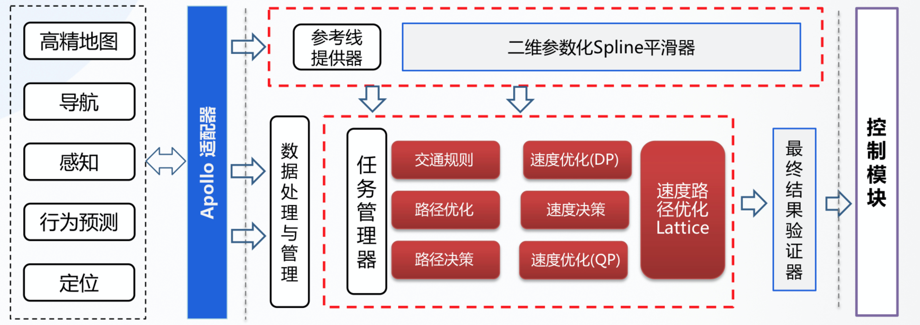
下面这幅图描述了本文所涉及的主要内容。建议读者先大致浏览一下这幅图,在阅读完本文之后再回顾一遍会比较好。
从这幅图中可以看出,这里涉及到三个模块:
- routing模块,这部分内容已经在Routing模块一文中讲解过,本文不再赘述。
- pnc_map模块:负责读取和处理Routing搜索结果。
- planning模块:根据Routing结果和车辆的实时状态(包括周边环境)生成参考线和轨迹。
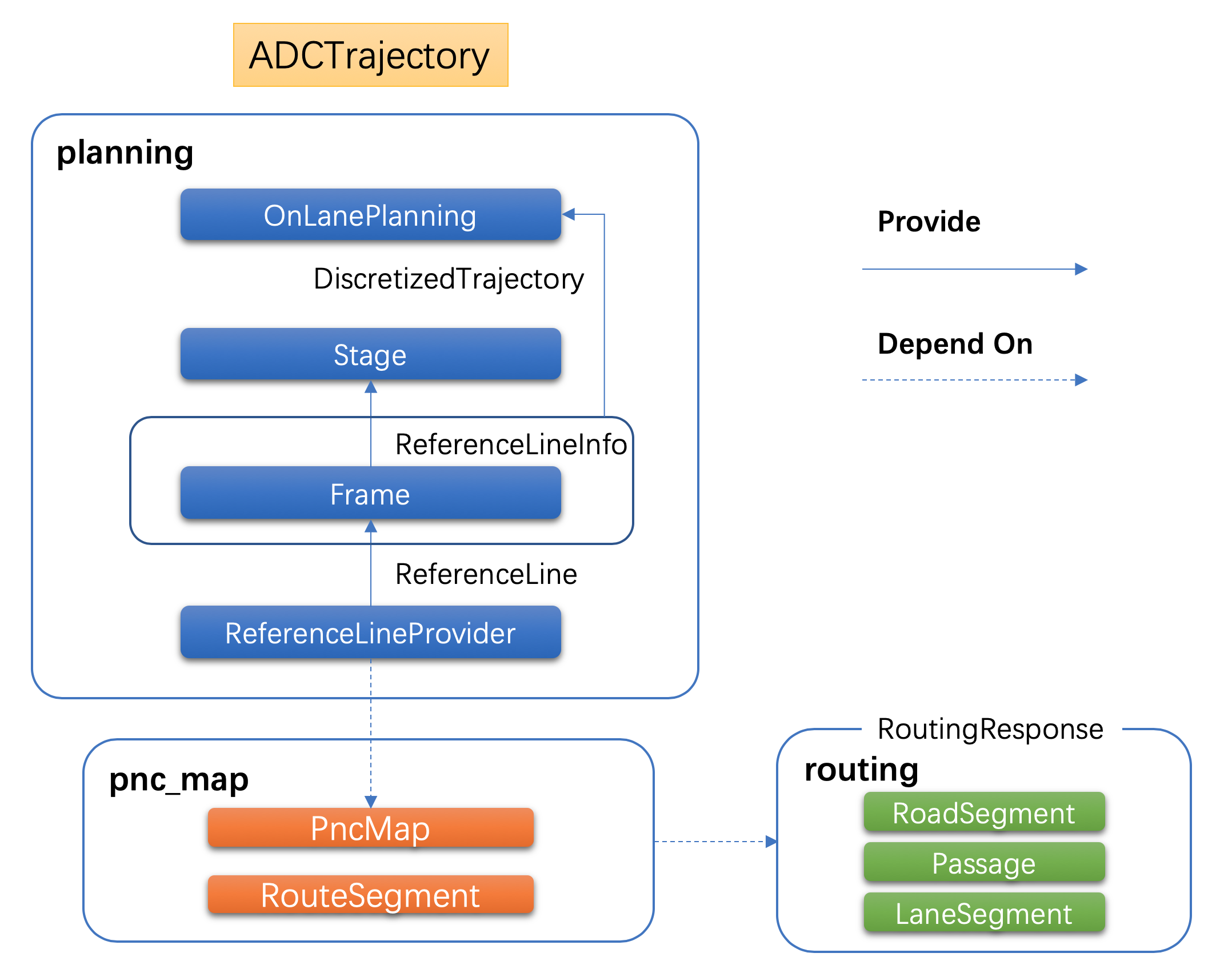
在Planning模块中有以下三个数据结构将是本文关注的重点:
ReferenceLine:原始参考线,源码位于planning/reference_line/目录下。根据Routing的搜索结果生成。ReferenceLineInfo:源码位于planning/common/目录下。Planning实现中,逻辑计算的基础数据结构,很多操作都会在这个数据结构上进行(例如:交通规则逻辑,障碍物投影,路径优化,速度决策等)。本文中的“参考线”一词将不区分ReferenceLine和ReferenceLineInfo两个结构。Trajectory:下文中我们将看到,有好几个结构用来描述轨迹。它们在不同的场合下使用。这其中,ADCTrajectory是Planning模块的输出。它是Planning模块一次计算循环中,处理了所有逻辑的最终结果,包含了车辆行驶需要的所有信息。因此,这个数据将直接影响到自动驾驶车辆的行车行为。
ReferenceLine和ReferenceLineInfo的关系?
ReferenceLine提供的是轨迹信息,而ReferenceLineInfo在ReferenceLine的基础上新添加了决策信息、ST图等。
重要扩展:《apollo介绍之参考线(二十七)》
注:对于决策和优化的知识需要更多的内容来讲解,因此这部分内容本文不会涉及。这些内容会通过其他文章来说明。
下文将根据从下往上的顺序来进行讲解。
pnc_map
pnc全称是Planning And Control。这是Planning用来对接Routing搜索结果的子模块。
数据结构
接下来先看一下几个主要的数据结构,这些结构是在Planning模块的实现中频繁见到。
RoutingRequest和RoutingResponse两个结构我们已经在Routing模块一文中讲解过,这里不再贴出。
PointENU:描述了地图上的一个点。定位,感知,预测和决策模块都会使用这个数据结构。目前,Apollo地图使用Universal Transverse Mercator坐标系统。在一些情况下,z字段可能会被忽略。
# modules/common/proto/geometry.proto

message PointENU {
  optional double x = 1 [default = nan];  // East from the origin, in meters.
  optional double y = 2 [default = nan];  // North from the origin, in meters.
  optional double z = 3 [default = 0.0];  // Up from the WGS-84 ellipsoid, in meters.
}
SLPoint:描述了Frenet坐标系上的一个点。s表示距离起点的纵向距离,l表示距离中心线的侧向距离。
# modules/common/proto/pnc_point.proto

message SLPoint {
  optional double s = 1;
  optional double l = 2;
}
LaneWaypoint:描述了车道上的点。
// modules/map/pnc_map/path.h

using LaneInfoConstPtr = std::shared_ptr<const LaneInfo>;

struct LaneWaypoint {
  LaneWaypoint() = default;
  LaneWaypoint(LaneInfoConstPtr lane, const double s)
      : lane(CHECK_NOTNULL(lane)), s(s) {}
  LaneWaypoint(LaneInfoConstPtr lane, const double s, const double l)
      : lane(CHECK_NOTNULL(lane)), s(s), l(l) {}
  LaneInfoConstPtr lane = nullptr;
  double s = 0.0;
  double l = 0.0;

  std::string DebugString() const;
};
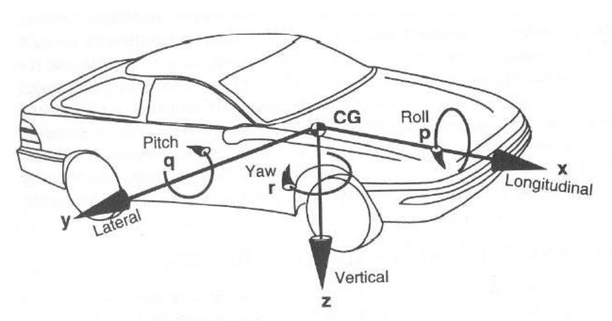
VehicleState:描述车辆状态,包含了自车位置,姿态,方向,速度,加速度等信息。
# modules/common/vehicle_state/proto/vehicle_state.proto

message VehicleState {
  optional double x = 1 [default = 0.0];
  optional double y = 2 [default = 0.0];
  optional double z = 3 [default = 0.0];
  optional double timestamp = 4 [default = 0.0];
  optional double roll = 5 [default = 0.0];
  optional double pitch = 6 [default = 0.0];
  optional double yaw = 7 [default = 0.0];
  optional double heading = 8 [default = 0.0];
  optional double kappa = 9 [default = 0.0];
  optional double linear_velocity = 10 [default = 0.0];
  optional double angular_velocity = 11 [default = 0.0];
  optional double linear_acceleration = 12 [default = 0.0];
  optional apollo.canbus.Chassis.GearPosition gear = 13;
  optional apollo.canbus.Chassis.DrivingMode driving_mode = 14;
  optional apollo.localization.Pose pose = 15;
}
roll,pitch和yaw分布描述了车辆在纵向,侧向和垂直方向上的角度,具体如下图所示:
RouteSegments
我们回顾一下,Routing的搜索结果RoutingResponse中包含了下面三个层次的结构:
RoadSegment:描述道路,一条道路可能包含了并行的几条通路(Passage)。Passage:描述通路,通路是直连不含变道的可行驶区域。一个通路可能包含了前后连接的多个车道。LaneSegment:描述车道,车道是道路中的一段,自动驾驶车辆会尽可能沿着车道的中心线行驶。
而pnc_map模块中的RouteSegments对应了上面的Passage结构,它其中会包含若干个车道信息。这个类继承自std::vector<LaneSegment>。
RouteSegments中有如下一些方法值得关注:
NextAction():车辆接下来要采取的动作。可能是直行,左变道,或者右变道。CanExit():当前通路是否可以接续到Routing结果的另外一个通路上。GetProjection():将一个点投影到当前通路上。返回SLPoint和LaneWaypoint。Stitch():缝合另外一个RouteSegments。即:去除两个RouteSegments间重合的多余部分,然后连接起来。Shrink():缩短到指定范围。IsOnSegment():车辆是否在当前RouteSegments上。IsNeighborSegment():当前RouteSegments是否是车辆的临近RouteSegments。
PncMap
PncMap类负责对接Routing搜索结果的更新。
PncMap会根据车辆当前位置,提供车辆周边的RouteSegments信息供ReferenceLineProvider生成ReferenceLine。“车辆周边”与车辆的纵向和横向相关,具体如下:
- 对于纵向来说,
PncMap返回的结果是前后一定范围内的。具体的范围由下面三个值决定:
// modules/map/pnc_map/pnc_map.cc

DEFINE_double(
look_backward_distance, 30,
"look backward this distance when creating reference line from routing");

DEFINE_double(look_forward_short_distance, 180,
"short look forward this distance when creating reference line "
"from routing when ADC is slow");

DEFINE_double(
look_forward_long_distance, 250,
"look forward this distance when creating reference line from routing");
即:向后是30米的范围。向前是根据车辆的速度返回180米或者250米的范围。
- 对于横向来说,如果Routing的搜索结果包含变道的信息。则
PncMap提供的数据会包含自车所在车道和变道后的相关通路。
PncMap中的下面这个方法用来接收车辆的状态更新。当然,这其中很重要的就是位置状态。
bool PncMap::UpdateVehicleState(const VehicleState &vehicle_state)
此时PncMap会计算车辆已经经过了哪些Routing的途经点,以及下一个目标点等信息。
在每一个Planning计算循环中,ReferenceLineProvider都会传入车辆的VehicleState给PncMap,并从PncMap获取车辆周围的通路(RouteSegments)。
PncMap中的下面这个方法返回Routing途经点还有哪些没有达到:
std::vector<routing::LaneWaypoint> PncMap::FutureRouteWaypoints() const
ReferenceLine结构
前面我们已经说了,参考线是根据车辆位置相对局部的一个数据,它包含了车辆前后一定范围内的路径信息。在车辆行驶过程中,Planning会在每一个计算周期中生成ReferenceLine。
这里我们先看一下ReferenceLine中主要包含了什么。
下面是ReferenceLine类中的数据成员:
// modules/planning/reference_line/reference_line.h

uint32_t priority_ = 0;
struct SpeedLimit {
  double start_s = 0.0;
  double end_s = 0.0;
  double speed_limit = 0.0;  // unit m/s
};
std::vector<SpeedLimit> speed_limit_;

std::vector<ReferencePoint> reference_points_;
hdmap::Path map_path_;
priority_是优先级,优先级则表示了当前参考线的优先级,用于后面有多个参考线的时候进行挑选,不过在PublicRoadPlanner中没有用到。speed_limit_是限速数据,速度限制主要标明参考线中哪些段有速度限制,因为是一个数组,因此一个参考线中可以有多段不同的限速。
reference_points_:参考线中的点也是一个数组,也就是说参考线是由参考点组成的,而map_path_则是最不好理解的,实际上map_path_就是地图中参考线,把参考线中的点转换到地图中,因此map_path_中的点和参考点数组的大小是一致的。
reference_points_其实是从map_path_得到,具体见ReferenceLine的构造函数。所以这两个数据的作用其实是一样的。
// modules/planning/reference_line/reference_line.cc

ReferenceLine::ReferenceLine(const MapPath& hdmap_path)
    : map_path_(hdmap_path) {
  for (const auto& point : hdmap_path.path_points()) {
    DCHECK(!point.lane_waypoints().empty());
    const auto& lane_waypoint = point.lane_waypoints()[0];
    reference_points_.emplace_back(
        hdmap::MapPathPoint(point, point.heading(), lane_waypoint), 0.0, 0.0);
  }
  CHECK_EQ(map_path_.num_points(), reference_points_.size());
}
std::vector<ReferencePoint>是一系列的点,点包含了位置的信息。因此这些点就是生成车辆行驶轨迹的基础数据。
ReferencePoint
ReferencePoint由MapPathPoint继承而来。下面这幅图是ReferencePoint的类继承关系。

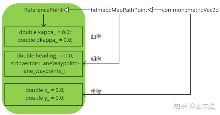
这里的几个类的说明如下:
Vec2d描述一个二维的点,包含的数据成员如下:double x_:描述点的x坐标。double y_:描述点的y坐标。
MapPathPoint描述了一个地图上的点,包含的数据成员如下:double heading_:描述点的朝向。std::vector<LaneWaypoint> lane_waypoints_:描述路径上的点。有些车道可能会存在重合的部分,所以地图上的一个点可能同时属于多个车道,因此这里的数据是一个vector结构。
ReferencePoint描述了参考线中的点,包含的数据成员如下:double kappa_:描述曲线的曲率。double dkappa_:描述曲率的导数。
除了坐标之外,ReferencePoint中的朝向和曲率也都是非常重要的数据。因为这些数据将直接影响车辆的方向控制。如果ReferenceLine中的ReferencePoint之间存在朝向和曲率大小震动或者数据跳变将可能导致车辆方向盘的相应变化,而这种变化对于乘车体验来说是非常糟糕的。
如果你打开Apollo项目中的demo地图文件你就会发现,地图中记录的仅仅是每个点x和y坐标,并没有记录heading和kappa数据。事实上,这些数据都是在读取地图原始点数据之后计算出来的。
对于heading的计算,位于path.cc中,相关代码如下:
// modules/map/pnc_map/path.cc#InitPoints

for (int i = 0; i < num_points_; ++i) {
accumulated_s_.push_back(s);
Vec2d heading;
if (i + 1 >= num_points_) {
  heading = path_points_[i] - path_points_[i - 1];
} else {
  segments_.emplace_back(path_points_[i], path_points_[i + 1]);
  heading = path_points_[i + 1] - path_points_[i];
  s += heading.Length();
}
heading.Normalize();
unit_directions_.push_back(heading);
}
这里遍历所有的点,通过两个点的坐标相减来计算两个点所代表向量,而一旦有了向量自然就知道其朝向了。这里的path_points_[i]是MapPathPoint类型的数据,而对于坐标点的减法和朝向的计算是在其父类Vec2d中完成的:
// modules/common/math/vec2d.cc

double Vec2d::Angle() const { return std::atan2(y_, x_); }

Vec2d Vec2d::operator-(const Vec2d &other) const {
  return Vec2d(x_ - other.x(), y_ - other.y());
}
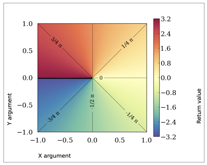
如果你没有用过atan2这个函数,请看这里。简单来说,atan2计算了arctan(yx)arctan(yx)的值,其返回值在(−Π,+Π](−Π,+Π]之间,如下图所示:
而对于曲率的计算,则是具体的Smoother中完成的。这里就不再赘述了。
创建ReferenceLine
了解了ReferenceLine结构之后,我们再看一下ReferenceLine是如何创建的。
在每一次计算循环中,Planning模块都会通过ReferenceLineProvider生成ReferenceLine。ReferenceLine由Routing的搜索结果决定。Routing是预先搜索出的全局可达路径,而ReferenceLine是车辆当前位置的前后一段范围。
直行的情况下,ReferenceLine是一个。而在需要变道的时候,会有多个ReferenceLine。
相关代码如下:
// modules/planning/reference_line/reference_line_provider.cc

bool ReferenceLineProvider::CreateReferenceLine(
    std::list<ReferenceLine> *reference_lines,
    std::list<hdmap::RouteSegments> *segments) {
  ...

  bool is_new_routing = false;
  {
    // Update routing in pnc_map
    if (pnc_map_->IsNewRouting(routing)) { ①
      is_new_routing = true;
      if (!pnc_map_->UpdateRoutingResponse(routing)) {
        AERROR << "Failed to update routing in pnc map";
        return false;
      }
    }
  }

  if (!CreateRouteSegments(vehicle_state, segments)) { ②
    AERROR << "Failed to create reference line from routing";
    return false;
  }
  if (is_new_routing || !FLAGS_enable_reference_line_stitching) {
    for (auto iter = segments->begin(); iter != segments->end();) {
      reference_lines->emplace_back();
      if (!SmoothRouteSegment(*iter, &reference_lines->back())) { ③
        AERROR << "Failed to create reference line from route segments";
        reference_lines->pop_back();
        iter = segments->erase(iter);
      } else {
        ++iter;
      }
    }
    return true;
  } else {  // stitching reference line
    for (auto iter = segments->begin(); iter != segments->end();) {
      reference_lines->emplace_back();
      if (!ExtendReferenceLine(vehicle_state, &(*iter),
                               &reference_lines->back())) { ④
        AERROR << "Failed to extend reference line";
        reference_lines->pop_back();
        iter = segments->erase(iter);
      } else {
        ++iter;
      }
    }
  }
  return true;
}
这里有几个地方需要注意:
- 前面我们已经说过,PncMap对接了Routing的搜索结果。如果Routing的路线变了,这里需要进行更新。
- 在行驶过程中,车辆的位置一直会变动(
vehicle_state中包含了这个信息)。CreateRouteSegments方法中会调用pnc_map_->GetRouteSegments(vehicle_state, segments)来获取车辆当前位置周边范围的RouteSegment。如果Routing的结果需要变道,则segments将是多个,否则就是一个(直行的情况)。 - 对于新的Routing,则根据
segments生成ReferenceLine,两者的数量是对应的。并且,ReferenceLine将直接从RouteSegment里面获取到道路的点的信息。 - 大部分情况下,在车辆行驶过程中,会不停的根据车辆的位置对
ReferenceLine进行长度延伸。ReferenceLine的长度是200多米的范围(往后30米左右,往前180米或者250米左右)。
在车辆行驶过程中,必不可少的就是判断自车以及障碍物所处的位置。这就很自然的需要将物体投影到参考线上来进行计算。对于这些内容,可以浏览下面这些接口的实现。这些逻辑基本上是点和位置的计算,这里就不展开了。
ReferencePoint GetReferencePoint(const double s) const;
common::FrenetFramePoint GetFrenetPoint(
  const common::PathPoint& path_point) const;
std::vector<ReferencePoint> GetReferencePoints(double start_s,
                                             double end_s) const;
size_t GetNearestReferenceIndex(const double s) const;
ReferencePoint GetNearestReferencePoint(const common::math::Vec2d& xy) const;
std::vector<hdmap::LaneSegment> GetLaneSegments(const double start_s,
                                              const double end_s) const;
ReferencePoint GetNearestReferencePoint(const double s) const;
ReferencePoint GetReferencePoint(const double x, const double y) const;
bool GetApproximateSLBoundary(const common::math::Box2d& box,
                            const double start_s, const double end_s,
                            SLBoundary* const sl_boundary) const;
bool GetSLBoundary(const common::math::Box2d& box,
                 SLBoundary* const sl_boundary) const;
bool GetSLBoundary(const hdmap::Polygon& polygon,
                 SLBoundary* const sl_boundary) const;
ReferenceLineSmoother
直接通过RouteSegments生成的ReferenceLine可能是不平滑的。
如果直接让车辆沿着不平滑的路线行驶可能造成车辆方向的抖动或者大幅变化,这对乘坐体验来说非常不好。因此,原始的路线数据需要经过算法的平滑。
具体的逻辑由下面这个方法完成:
// modules/planning/reference_line/reference_line_provider.cc

bool ReferenceLineProvider::SmoothReferenceLine(
    const ReferenceLine &raw_reference_line, ReferenceLine *reference_line) {
  if (!FLAGS_enable_smooth_reference_line) {
    *reference_line = raw_reference_line;
    return true;
  }
  // generate anchor points:
  std::vector<AnchorPoint> anchor_points;
  GetAnchorPoints(raw_reference_line, &anchor_points);
  smoother_->SetAnchorPoints(anchor_points);
  if (!smoother_->Smooth(raw_reference_line, reference_line)) {
    AERROR << "Failed to smooth reference line with anchor points";
    return false;
  }
  if (!IsReferenceLineSmoothValid(raw_reference_line, *reference_line)) {
    AERROR << "The smoothed reference line error is too large";
    return false;
  }
  return true;
}
很显然,smoother_->Smooth才是平滑算法的实现。
目前Apollo的Planning模块中内置了三个ReferenceLine平滑器,它们的结构如下:
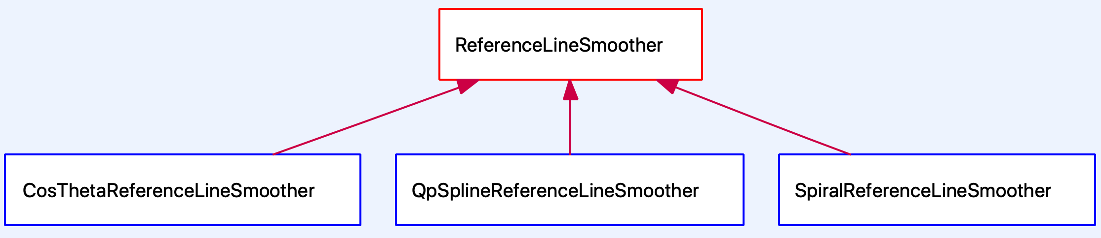
这是策略设计模式的应用。
具体使用哪一个平滑器由ReferenceLineProvider在初始化的时候读取配置文件来决定:
CHECK(common::util::GetProtoFromFile(FLAGS_smoother_config_filename,
                                     &smoother_config_))
  << "Failed to load smoother config file "
  << FLAGS_smoother_config_filename;
if (smoother_config_.has_qp_spline()) {
  smoother_.reset(new QpSplineReferenceLineSmoother(smoother_config_));
} else if (smoother_config_.has_spiral()) {
  smoother_.reset(new SpiralReferenceLineSmoother(smoother_config_));
} else if (smoother_config_.has_cos_theta()) {
  smoother_.reset(new CosThetaReferenceLineSmoother(smoother_config_));
} else {
  CHECK(false) << "unknown smoother config "
               << smoother_config_.DebugString();
}
目前,smoother_config_filename配置的值是/apollo/modules/planning/conf/qp_spline_smoother_config.pb.txt。因此,使用的是QpSplineReferenceLineSmoother。
DEFINE_string(smoother_config_filename,
              "/apollo/modules/planning/conf/qp_spline_smoother_config.pb.txt",
              "The configuration file for qp_spline smoother");
ReferenceLineSmoother算法
参考线平滑器使用了二次规划(Quadratic programming )和样条插值(Spline interpolation)算法。
这部分内容不是本文的重点,第一次阅读可以选择跳过。这些算法会在今后的文章中详细讲解。
目标函数
- 1.1 分段寻路路径:将寻路路径划分为 n 段,每段用2个多项式表示:
- 1.2 定义样条段优化目标函数
- 1.3 将开销(cost)函数转换为QP公式,QP公式如下:
约束条件
- 2.1 平滑节点约束:该约束的目的是使样条的节点更加平滑。假设两个段
和
互相连接,且
。计算约束的等式为:
同样地,该公式也适用于下述等式:
- 2.2 点采样边界约束:在路径上均匀的取样 m 个点并检查这些点的预定义边界。
创建ReferenceLineInfo
ReferenceLineInfo由Frame根据ReferenceLine和RouteSegments创建得到。
在每个Planning计算循环的开始,都会创建和初始化一个新的Frame,而Frame初始化的时候就会创建ReferenceLineInfo。当有多个ReferenceLine的时候,则意味着需要变道。
bool Frame::CreateReferenceLineInfo(
    const std::list<ReferenceLine> &reference_lines,
    const std::list<hdmap::RouteSegments> &segments) {
  reference_line_info_.clear();
  auto ref_line_iter = reference_lines.begin();
  auto segments_iter = segments.begin();
  while (ref_line_iter != reference_lines.end()) {
    if (segments_iter->StopForDestination()) {
      is_near_destination_ = true;
    }
    reference_line_info_.emplace_back(vehicle_state_, planning_start_point_,
                                      *ref_line_iter, *segments_iter);
    ++ref_line_iter;
    ++segments_iter;
  }

  if (FLAGS_enable_change_lane_decider &&
      !change_lane_decider_.Apply(&reference_line_info_)) {
    AERROR << "Failed to apply change lane decider";
    return false;
  }
  ...
}
ReferenceLine主要是静态数据(路径点和限速)的存储,而ReferenceLineInfo中会包含动态信息(障碍物)和更多逻辑。
操作ReferenceLineInfo
主要有下面两个地方会操作ReferenceLineInfo:
/modules/planning/traffic_rules:该目录下是交通规则的实现。不同Rule会向ReferenceLineInfo添加不同的数据,例如:障碍物,红绿灯等等。/modules/planning/tasks:该目录下是许多的决策器和优化器,这是Apollo EM Planner算法的核心。不过前面已经说过,由于篇幅所限,本文不会涉及这些内容。
在《解析百度Apollo之决策规划模块》 一文中我们已经提到,交通规则的应用是在TrafficDecider::Execute方法中执行的。
每个交通规则都会实现下面这个方法来完成其逻辑:
common::Status ApplyRule(Frame* const frame,
                         ReferenceLineInfo* const reference_line_info) = 0;
这里的指针类型的参数就意味着方法实现可能会修改参数的值。
对于ReferenceLineInfo的操作,主要是修改该类的以下三个字段:
PathData path_data_:包含了路径相关的数据,逻辑实现位于modules/planning/common/path/中。SpeedData speed_data_:包含了速度相关的数据,逻辑实现位于modules/planning/common/speed/。路径和速度最终将组合起来使用,以生成行车轨迹(见下文)。PathDecision path_decision_:这个字段中包含了障碍物的决策信息。
障碍物在Planning模块中通过apollo::planning::Obstacle描述。
障碍物分为横向障碍物和纵向障碍物。横向障碍物将可能导致车辆的nudge行为。而纵向障碍物可能导致车辆出现:stop,yield,follow,overtake行为。这几个行为的优先级从左到右依次递减。
预测模块对于同一个障碍物可能会有多个预测轨迹。此时在Planning模块中,会多个
apollo::planning::Obstacle对象分别对应每一个轨迹。
轨迹结构
前面我们已经多次提到“轨迹”一次。我们知道,”轨迹“不同于“路径”,“轨迹”不仅仅包含了行驶路线,还要包含每个时刻的车辆的速度,加速度,方向转向等信息。
就和高精地图通过一系列的点来描述道路的中心线一样,车辆的行驶轨迹也是由一系列的点来描述的。具体的结构在proto文件中定义,如下所示:
// common/proto/pnc_point.proto

message PathPoint {
  optional double x = 1;
  optional double y = 2;
  optional double z = 3;
  optional double theta = 4;
  optional double kappa = 5;
  optional double s = 6;

  optional double dkappa = 7;
  optional double ddkappa = 8;
  optional string lane_id = 9;

  optional double x_derivative = 10;
  optional double y_derivative = 11;
}

message TrajectoryPoint {
  optional PathPoint path_point = 1;
  optional double v = 2;  // in [m/s]
  optional double a = 3;
  optional double relative_time = 4;
  optional double da = 5;
  optional double steer = 6;
}
轨迹中的点通过TrajectoryPoint这个结构来描述。它的字段说明如下:
path_point:PathPoint类型数据。描述了一个点的位置,曲率,朝向,所属车道等信息。v:描述车辆的速度。a:描述车辆的加速度。relative_time:描述车辆达到该点的相对时间(以轨迹的开始为起点)。da:加速度的导数,也称之为jerk。steer:车辆的前轮方向。
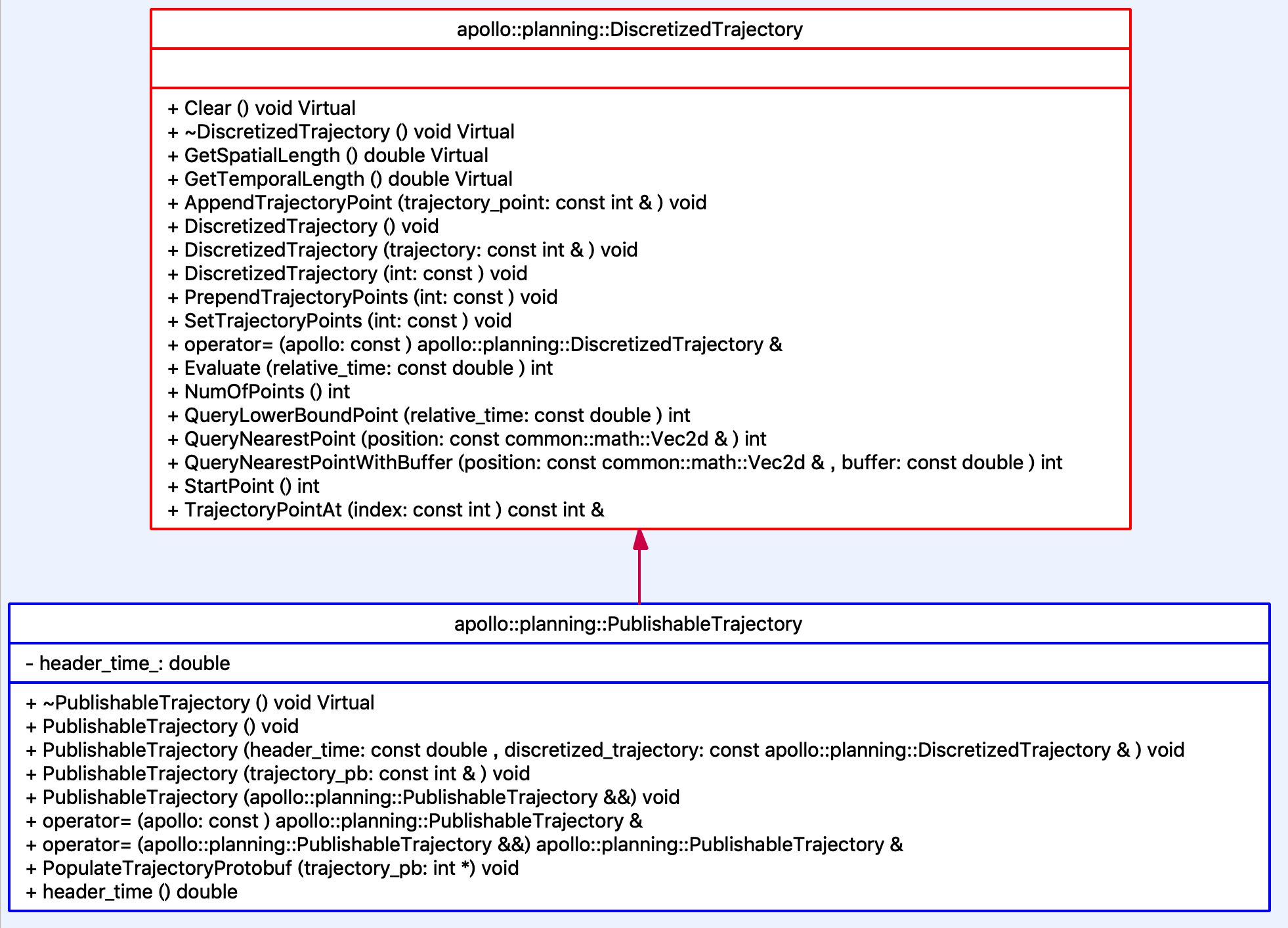
TrajectoryPoint仅仅是一个点。而一条轨迹一定是由许多个点构成的。因此,描述轨迹的类DiscretizedTrajectory继承自std::vector<common::TrajectoryPoint>。如下所示:
class DiscretizedTrajectory : public std::vector<common::TrajectoryPoint>
DiscretizedTrajectory还有一个子类PublishableTrajectory,它们的类结构如下图所示:
PublishableTrajectory相较于DiscretizedTrajectory来说,最主要的提供了下面这个方法:
explicit PublishableTrajectory(const ADCTrajectory& trajectory_pb);
这个方法是将Planning模块中的轨迹数据结构导出到可发布的状态。这里的ADCTrajectory是Planning最终往外发出的数据结构,它也是在proto文件中定义的。 这个数据结构比较大,字段上已经包含了描述。因此这里就不多做说明了。
# modules/planning/proto/planning.proto

message ADCTrajectory {
  optional apollo.common.Header header = 1;

  optional double total_path_length = 2;  // in meters
  optional double total_path_time = 3;    // in seconds

  // path data + speed data
  repeated apollo.common.TrajectoryPoint trajectory_point = 12;

  optional EStop estop = 6;

  // path point without speed info
  repeated apollo.common.PathPoint path_point = 13;

  // is_replan == true mean replan triggered
  optional bool is_replan = 9 [default = false];
  optional string replan_reason = 22;

  // Specify trajectory gear
  optional apollo.canbus.Chassis.GearPosition gear = 10;

  optional apollo.planning.DecisionResult decision = 14;

  optional LatencyStats latency_stats = 15;

  // the routing used for current planning result
  optional apollo.common.Header routing_header = 16;
  optional apollo.planning_internal.Debug debug = 8;

  enum RightOfWayStatus {
    UNPROTECTED = 0;
    PROTECTED = 1;
  }
  optional RightOfWayStatus right_of_way_status = 17;

  // lane id along reference line
  repeated apollo.hdmap.Id lane_id = 18;

  // set the engage advice for based on current planning result.
  optional apollo.common.EngageAdvice engage_advice = 19;

  // the region where planning cares most
  message CriticalRegion {
    repeated apollo.common.Polygon region = 1;
  }

  // critial region will be empty when planning is NOT sure which region is
  // critical
  // critial regions may or may not overlap
  optional CriticalRegion critical_region = 20;

  enum TrajectoryType {
    UNKNOWN = 0;
    NORMAL = 1;
    PATH_FALLBACK = 2;
    SPEED_FALLBACK = 3;
  }
  optional TrajectoryType trajectory_type = 21 [default = UNKNOWN];

  // output related to RSS
  optional RSSInfo rss_info = 100;
}
生成轨迹
从参考线到生成轨迹是由ReferenceLineInfo::CombinePathAndSpeedProfile方法完成的。
在EM Planner中,路径和速度是分开优化的,这里是在将这两个优化的结果(记录在ReferenceLineInfo的path_data_和speed_data_中)合并成最终的结果。
bool ReferenceLineInfo::CombinePathAndSpeedProfile(
    const double relative_time, const double start_s,
    DiscretizedTrajectory* ptr_discretized_trajectory) {
  ...

  for (double cur_rel_time = 0.0; cur_rel_time < speed_data_.TotalTime();
       cur_rel_time += (cur_rel_time < kDenseTimeSec ? kDenseTimeResoltuion
                                                     : kSparseTimeResolution)) { ①
    common::SpeedPoint speed_point;
    if (!speed_data_.EvaluateByTime(cur_rel_time, &speed_point)) {
      AERROR << "Fail to get speed point with relative time " << cur_rel_time;
      return false;
    }

    if (speed_point.s() > path_data_.discretized_path().Length()) {
      break;
    }
    common::PathPoint path_point;
    if (!path_data_.GetPathPointWithPathS(speed_point.s(), &path_point)) { ②
      AERROR << "Fail to get path data with s " << speed_point.s()
             << "path total length " << path_data_.discretized_path().Length();
      return false;
    }
    path_point.set_s(path_point.s() + start_s);

    common::TrajectoryPoint trajectory_point; ③
    trajectory_point.mutable_path_point()->CopyFrom(path_point);
    trajectory_point.set_v(speed_point.v());
    trajectory_point.set_a(speed_point.a());
    trajectory_point.set_relative_time(speed_point.t() + relative_time);
    ptr_discretized_trajectory->AppendTrajectoryPoint(trajectory_point); ④
  }
  return true;
}
这段代码中的四个点说明如下:
- 根据
speed_data_中记录的总时间和间隔以确定需要在轨迹中添加多少个点。 - 根据
path_data_中的数据获取相应的点以确定轨迹点的位置。 - 创建一个轨迹点
TrajectoryPoint并设置位置和速度,加速度和相对时间等信息。 - 在轨迹中添加一个轨迹点。
有了轨迹之后,便可以发出供车辆行驶了。相关代码如下:
Status OnLanePlanning::Plan(
    const double current_time_stamp,
    const std::vector<TrajectoryPoint>& stitching_trajectory,
    ADCTrajectory* const trajectory_pb) {
  ...
  auto status = planner_->Plan(stitching_trajectory.back(), frame_.get());  ①

  ptr_debug->mutable_planning_data()->set_front_clear_distance(
      EgoInfo::Instance()->front_clear_distance());

  const auto* best_ref_info = frame_->FindDriveReferenceLineInfo();  ②
  ...
  trajectory_pb->mutable_latency_stats()->MergeFrom(
      best_ref_info->latency_stats());
  // set right of way status
  trajectory_pb->set_right_of_way_status(best_ref_info->GetRightOfWayStatus());
  for (const auto& id : best_ref_info->TargetLaneId()) {
    trajectory_pb->add_lane_id()->CopyFrom(id); ③
  }

  trajectory_pb->set_trajectory_type(best_ref_info->trajectory_type());

  if (FLAGS_enable_rss_info) {
    trajectory_pb->mutable_rss_info()->CopyFrom(best_ref_info->rss_info());
  }

  best_ref_info->ExportDecision(trajectory_pb->mutable_decision());

  ...
  last_publishable_trajectory_.reset(new PublishableTrajectory(
      current_time_stamp, best_ref_info->trajectory())); ④
  ...

  if (FLAGS_enable_stitch_last_trajectory) {
    last_publishable_trajectory_->PrependTrajectoryPoints(
        std::vector<TrajectoryPoint>(stitching_trajectory.begin(),
                                     stitching_trajectory.end() - 1));
  }

  last_publishable_trajectory_->PopulateTrajectoryProtobuf(trajectory_pb); ⑤

  best_ref_info->ExportEngageAdvice(trajectory_pb->mutable_engage_advice());

  return status;
}
这段代码中的几个点说明如下:
planner_->Plan是执行每个Planner的主体算法逻辑。- 在有多个
ReferenceLineInfo的情况下,选取最合适的一条。 - 记录
ReferenceLineInfo包含的lane id。 - 将轨迹的数据格式转换成
PublishableTrajectory类型并记录到last_publishable_trajectory_中。 - 导出成最终格式:
ADCTrajectory。Apollo 3.5已经改用新的框架Cyber RT,最终轨迹的发出是在Cyber Component的实现PlanningComponent发出。相关代码如下:
  ADCTrajectory adc_trajectory_pb;
  planning_base_->RunOnce(local_view_, &adc_trajectory_pb);
  auto start_time = adc_trajectory_pb.header().timestamp_sec();
  common::util::FillHeader(node_->Name(), &adc_trajectory_pb);

  // modify trajectory relative time due to the timestamp change in header
  const double dt = start_time - adc_trajectory_pb.header().timestamp_sec();
  for (auto& p : *adc_trajectory_pb.mutable_trajectory_point()) {
    p.set_relative_time(p.relative_time() + dt);
  }
  planning_writer_->Write(std::make_shared<ADCTrajectory>(adc_trajectory_pb));
至此,决策规划模块的任务就完成了。接下来就是由控制模块按照这里发出的轨迹来控制车辆的行驶。
参考资料与推荐读物
- Apollo Planning Source Code
- Apollo reference line smoother
- YannZyl/Apollo-Note/参考线提供器: ReferenceLineProvider
- Comparison of Three Degree of Freedom and Six Degree of Freedom Motion Bases Utilizing Classical Washout Algorithms
原文地址:《解析百度Apollo之参考线与轨迹》 by 保罗的酒吧