说明:本文旨在详细解析STM32的外部中断,以实现按键触发外部中断。其中包含“编程流程”、“程序代码”、“代码解析”、“原理分析”、“小结”五部分。
一、编程流程
要实现STM32外部中断,按照基本流程来讲,初步的想法重点应该是端口配置、中断服务函数,具体可分为四部分:
①初始化GPIO;
②初始化EXTI;
③初始化NVIC;
④配置中断服务函数。
二、程序代码
/**
  * @brief  GPIO Init structure definition(<stm32f10x_gpio.h>库已包含)
  */
typedef struct
{
  uint16_t GPIO_Pin;             /*!< Specifies the GPIO pins to be configured.
                                      This parameter can be any value of @ref GPIO_pins_define */
  GPIOSpeed_TypeDef GPIO_Speed;  /*!< Specifies the speed for the selected pins.
                                      This parameter can be a value of @ref GPIOSpeed_TypeDef */
  GPIOMode_TypeDef GPIO_Mode;    /*!< Specifies the operating mode for the selected pins.
                                      This parameter can be a value of @ref GPIOMode_TypeDef */
}GPIO_InitTypeDef;

/**
  * @brief  EXTI Init Structure definition (<stm32f10x_exti.h>库已包含)
  */

typedef struct
{
  uint32_t EXTI_Line;               /*!< Specifies the EXTI lines to be enabled or disabled.
                                         This parameter can be any combination of @ref EXTI_Lines */
  EXTIMode_TypeDef EXTI_Mode;       /*!< Specifies the mode for the EXTI lines.
                                         This parameter can be a value of @ref EXTIMode_TypeDef */
  EXTITrigger_TypeDef EXTI_Trigger; /*!< Specifies the trigger signal active edge for the EXTI lines.
                                         This parameter can be a value of @ref EXTIMode_TypeDef */
  FunctionalState EXTI_LineCmd;     /*!< Specifies the new state of the selected EXTI lines.
                                         This parameter can be set either to ENABLE or DISABLE */
}EXTI_InitTypeDef;

/**
  *@brief   NVIC_Configuration实现NVIC配置
  *
  */
static void NVIC_Configuration()
{
    NVIC_InitTypeDef NVIC_InitStructure;

    NVIC_PriorityGroupConfig(NVIC_PriorityGroup_1);           //配置NVIC优先级分组为1

    NVIC_InitStructure.NVIC_IRQChannel = EXTI9_5_IRQn;        //中断源:[9:5],位于“stm32f10x.h”中
    NVIC_InitStructure.NVIC_IRQChannelPreemptionPriority = 1; //抢占优先级:1
    NVIC_InitStructure.NVIC_IRQChannelSubPriority = 1;        //子优先级:1
    NVIC_InitStructure.NVIC_IRQChannelCmd = ENABLE;           //使能中断通道
    NVIC_Init(&NVIC_InitStructure);
}
/**
  * @brief  KEY_Configuration按键配置
  */
void KEY_Configuration()
{
    GPIO_InitTypeDef GPIO_InitStructure;                      //定义GPIO_InitTypeDef结构体

    RCC_APB2PeriphClockCmd( RCC_APB2Periph_GPIOB | \
                            RCC_APB2Periph_AFIO, ENABLE);     //开启GPIOB和复用功能时钟
    GPIO_DeInit(GPIOB);                                       //将外设GPIOB寄存器重设为缺省值(强制或释放APB2外设复位)
    GPIO_InitStructure.GPIO_Pin = GPIO_Pin_8;                 //选择GPIO_Pin_8
    GPIO_InitStructure.GPIO_Mode = GPIO_Mode_IPU;             //选择上拉输入模式
    GPIO_Init(GPIOB, &GPIO_InitStructure);                    //初始化以上参数
}
/**
  * @brief  EXTI_Configuration配置EXTI
  */
void EXTI_Configuration()
{
    KEY_Configuration();

    GPIO_EXTILineConfig(GPIO_PortSourceGPIOB, GPIO_PinSource8); //选择EXTI信号源

    EXTI_InitTypeDef EXTI_InitStructure;
    EXTI_InitStructure.EXTI_Line = EXTI_Line8;               //中断线选择
    EXTI_InitStructure.EXTI_Mode = EXTI_Mode_Interrupt;      //EXTI为中断模式
    EXTI_InitStructure.EXTI_Trigger = EXTI_Trigger_Falling;  //下降沿触发
    EXTI_InitStructure.EXTI_LineCmd = ENABLE;                //使能中断
    EXTI_Init(&EXTI_InitStructure);

    NVIC_Configuration();                                     //配置NVIC中断
}
/**
  * @brief  中断服务函数
  */
void EXTI9_5_IRQHandler(void)                       //EXTI_Line:9...5
{
  if(EXTI_GetITStatus(EXTI_Line8)!= RESET)
  {
    EXTI_ClearITPendingBit(EXTI_Line8);
    if(ledstate == 0)
    {
        ledstate = 1;   //标志位
        LEDON;          //LED开启
    }
    else if(ledstate == 1)
    {
        ledstate = 0;  //标志位
        LEDOFF;        //LED关闭
    }
  }
}
备注:届时只需要在主函数中调用EXTI_Configuration();函数即可。
三、代码解析
1、初始化GPIO:
①开启GPIOX时钟和复用时钟:
RCC_APB2PeriphClockCmd( RCC_APB2Periph_GPIOB | RCC_APB2Periph_AFIO, ENABLE);②初始化GPIO模式和对应管脚:
GPIO_InitTypeDef GPIO_InitStructure;
GPIO_InitStructure.GPIO_Pin = GPIO_Pin_8;                 //选择GPIO_Pin_8
GPIO_InitStructure.GPIO_Mode = GPIO_Mode_IPU;             //选择上拉输入模式
GPIO_Init(GPIOB, &GPIO_InitStructure);                    //初始化以上参数
2、初始化EXTI:
①选择EXTI信号源:
GPIO_EXTILineConfig(GPIO_PortSourceGPIOB, GPIO_PinSource8);②确定中断线、中断模式、触发方式并使能:
EXTI_InitTypeDef EXTI_InitStructure;
EXTI_InitStructure.EXTI_Line = EXTI_Line8;               //中断线选择
EXTI_InitStructure.EXTI_Mode = EXTI_Mode_Interrupt;      //EXTI为中断模式
EXTI_InitStructure.EXTI_Trigger = EXTI_Trigger_Falling;  //下降沿触发
EXTI_InitStructure.EXTI_LineCmd = ENABLE;                //使能中断
EXTI_Init(&EXTI_InitStructure);
3、初始化NVIC:
①配置NVIC优先级分组:
NVIC_PriorityGroupConfig(NVIC_PriorityGroup_1);②确定中断源、优先级(抢占优先级和子优先级),使能:
NVIC_InitTypeDef NVIC_InitStructure;
NVIC_InitStructure.NVIC_IRQChannel = EXTI9_5_IRQn;        //中断源:[9:5],位于<stm32f10x.h>中
NVIC_InitStructure.NVIC_IRQChannelPreemptionPriority = 1; //抢占优先级:1
NVIC_InitStructure.NVIC_IRQChannelSubPriority = 1;        //子优先级:1
NVIC_InitStructure.NVIC_IRQChannelCmd = ENABLE;           //使能中断通道
NVIC_Init(&NVIC_InitStructure);
4、配置中断服务函数:
①判断是否进入中断:
 if(EXTI_GetITStatus(EXTI_Line8)!= RESET)
 {

 }
②中断行为处理:

if(ledstate == 0)
{
    ledstate = 1;   //标志位
    LEDON;          //LED开启
}
else if(ledstate == 1)
{
    ledstate = 0;  //标志位
    LEDOFF;        //LED关闭
}
③清位:
EXTI_ClearITPendingBit(EXTI_Line8);四、原理分析
1、RCC_APB2PeriphClockCmd(uint32_t RCC_APB2Periph, FunctionalState NewState);函数:(从代码库和固件库手册两方面来看)
首先,库里面是这样定义的:
/**
  * @brief  Enables or disables the High Speed APB (APB2) peripheral clock.
  * @param  RCC_APB2Periph: specifies the APB2 peripheral to gates its clock.
  *   This parameter can be any combination of the following values:
  *     @arg RCC_APB2Periph_AFIO, RCC_APB2Periph_GPIOA, RCC_APB2Periph_GPIOB,
  *          RCC_APB2Periph_GPIOC, RCC_APB2Periph_GPIOD, RCC_APB2Periph_GPIOE,
  *          RCC_APB2Periph_GPIOF, RCC_APB2Periph_GPIOG, RCC_APB2Periph_ADC1,
  *          RCC_APB2Periph_ADC2, RCC_APB2Periph_TIM1, RCC_APB2Periph_SPI1,
  *          RCC_APB2Periph_TIM8, RCC_APB2Periph_USART1, RCC_APB2Periph_ADC3,
  *          RCC_APB2Periph_TIM15, RCC_APB2Periph_TIM16, RCC_APB2Periph_TIM17,
  *          RCC_APB2Periph_TIM9, RCC_APB2Periph_TIM10, RCC_APB2Periph_TIM11
  * @param  NewState: new state of the specified peripheral clock.
  *   This parameter can be: ENABLE or DISABLE.
  * @retval None
  */
void RCC_APB2PeriphClockCmd(uint32_t RCC_APB2Periph, FunctionalState NewState)
{
  /* Check the parameters */
  assert_param(IS_RCC_APB2_PERIPH(RCC_APB2Periph));
  assert_param(IS_FUNCTIONAL_STATE(NewState));
  if (NewState != DISABLE)
  {
    RCC->APB2ENR |= RCC_APB2Periph;
  }
  else
  {
    RCC->APB2ENR &= ~RCC_APB2Periph;
  }
}其次,固件库手册这样写:
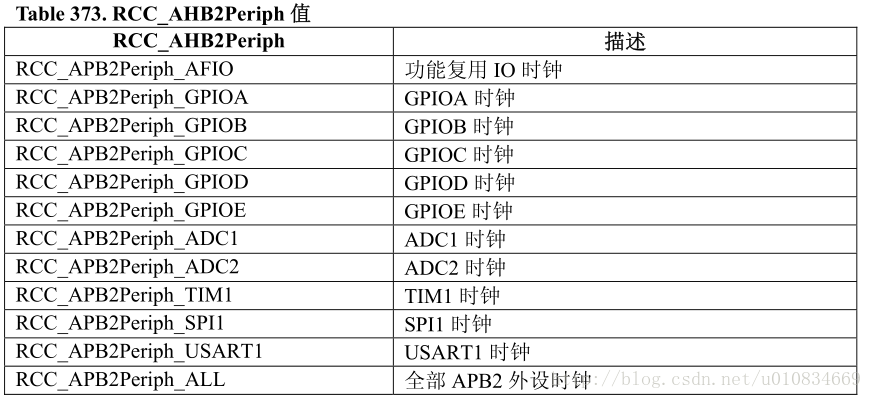
即该函数实现“使能或者失能 APB2 外设时钟”。
最后,分析函数RCC_APB2PeriphClockCmd(…,…)的内部构成:
①以下两句代码,用于检测参数正确性。
assert_param(IS_RCC_APB2_PERIPH(RCC_APB2Periph));
assert_param(IS_FUNCTIONAL_STATE(NewState));
其中,assert_param(…);的函数原型在“stm32f10x_conf.h”里面,如下。其原型采用了#ifdef/#else/#endif的形式,称为“断言机制”,即
- 如果未定义USE_FULL_ASSERT,或者USE_FULL_ASSERT为0,则此句不执行,为空语句。
- 相反,如果定义了USE_FULL_ASSERT为1,则执行“((expr) ? (void)0 : assert_failed((uint8_t *)_ FILE_, _ LINE __))”。其中expr在本例中为“IS_RCC_APB2_PERIPH(RCC_APB2Periph)”,就是在编译时,判断expr是否为0的一句代码。
但是,此处要注意到是_ FILE_和 _ LINE_,是标准库函数中的宏定义。
/* Exported types ------------------------------------------------------------*/
/* Exported constants --------------------------------------------------------*/
/* Uncomment the line below to expanse the "assert_param" macro in the
   Standard Peripheral Library drivers code */
/* #define USE_FULL_ASSERT    1 */

/* Exported macro ------------------------------------------------------------*/
#ifdef  USE_FULL_ASSERT

/**
  * @brief  The assert_param macro is used for function's parameters check.
  * @param  expr: If expr is false, it calls assert_failed function which reports
  *         the name of the source file and the source line number of the call
  *         that failed. If expr is true, it returns no value.
  * @retval None
  */
  #define assert_param(expr) ((expr) ? (void)0 : assert_failed((uint8_t *)__FILE__, __LINE__))
/* Exported functions ------------------------------------------------------- */
  void assert_failed(uint8_t* file, uint32_t line);
#else
  #define assert_param(expr) ((void)0)
#endif /* USE_FULL_ASSERT */
而assert_failed的函数原型如下,可以在while(1)中添加处理函数,比如printf,用来指示错误所在的文件和行数。
void assert_failed(uint8_t* file, uint32_t line)
{
    while (1)
    {
    }
}
②第二个要点:RCC->APB2ENR |= RCC_APB2Periph;和RCC->APB2ENR &= ~RCC_APB2Periph;
复位和时钟控制寄存器RCC:0x40000000+0x20000+0x1000,包含十个寄存器,写在同个结构体类型中,APB2ENR为APB2外设时钟使能寄存器,RCC_APB2Periph即为函数形参,二者进行|=操作,即是选中某个寄存器,最后对其进行使能或失能。
2、GPIO_EXTILineConfig(uint8_t GPIO_PortSource, uint8_t GPIO_PinSource),用于选择 GPIO 管脚用作外部中断线路。
首先,库里面是这样定义的:
/**
 * @brief  Selects the GPIO pin used as EXTI Line.
 * @param  GPIO_PortSource: selects the GPIO port to be used as source for EXTI lines.
 *   This parameter can be GPIO_PortSourceGPIOx where x can be (A..G).
 * @param  GPIO_PinSource: specifies the EXTI line to be configured.
 *   This parameter can be GPIO_PinSourcex where x can be (0..15).
 * @retval None
  */
void GPIO_EXTILineConfig(uint8_t GPIO_PortSource, uint8_t GPIO_PinSource)
{
  uint32_t tmp = 0x00;
  /* Check the parameters */
  assert_param(IS_GPIO_EXTI_PORT_SOURCE(GPIO_PortSource));
  assert_param(IS_GPIO_PIN_SOURCE(GPIO_PinSource));

  tmp = ((uint32_t)0x0F) << (0x04 * (GPIO_PinSource & (uint8_t)0x03));
  AFIO->EXTICR[GPIO_PinSource >> 0x02] &= ~tmp;
  AFIO->EXTICR[GPIO_PinSource >> 0x02] |= (((uint32_t)GPIO_PortSource) << (0x04 * (GPIO_PinSource & (uint8_t)0x03)));
}
然后,分析 GPIO_EXTILineConfig(…,…)的内部构成:
①assert_param(…)与上面说的功能一致;
②第16行和17行:
第16行的结果是:0x0F。(以GPIO_PinSource8为例)
第17行中~temp的值为0xF0,GPIO_PinSource >> 0x02的值为0x02(以GPIO_PinSource8为例),AFIO的值为0x40000000+0x10000+0x0000==0x40010000,总体来讲,就是将AFIO_EXTICR寄存器的第4~7位清空。
- AFIO_EXTICR为外部中断配置寄存器,总共有4个,每个寄存器对应4个EXTI,分别遍及EXTI0~EXTI15。
③第18行,再一次给该寄存器置位,进行端口选择。
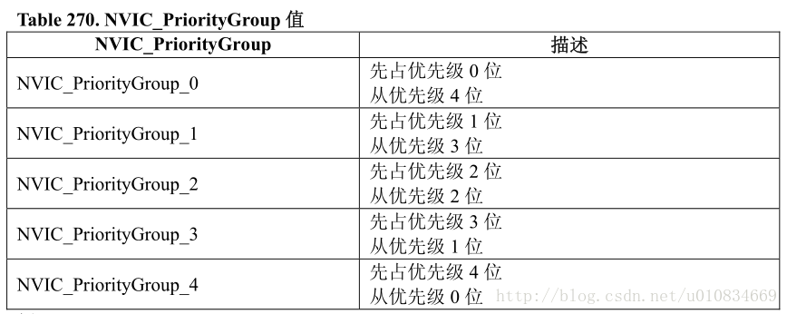
3、void NVIC_PriorityGroupConfig(uint32_t NVIC_PriorityGroup)函数用于NVIC优先级分组。
首先,库函数里面是这样定义的:
/**
  * @brief  Configures the priority grouping: pre-emption priority and subpriority.
  * @param  NVIC_PriorityGroup: specifies the priority grouping bits length.
  *   This parameter can be one of the following values:
  *     @arg NVIC_PriorityGroup_0: 0 bits for pre-emption priority
  *                                4 bits for subpriority
  *     @arg NVIC_PriorityGroup_1: 1 bits for pre-emption priority
  *                                3 bits for subpriority
  *     @arg NVIC_PriorityGroup_2: 2 bits for pre-emption priority
  *                                2 bits for subpriority
  *     @arg NVIC_PriorityGroup_3: 3 bits for pre-emption priority
  *                                1 bits for subpriority
  *     @arg NVIC_PriorityGroup_4: 4 bits for pre-emption priority
  *                                0 bits for subpriority
  * @retval None
  */
void NVIC_PriorityGroupConfig(uint32_t NVIC_PriorityGroup)
{
  /* Check the parameters */
  assert_param(IS_NVIC_PRIORITY_GROUP(NVIC_PriorityGroup));

  /* Set the PRIGROUP[10:8] bits according to NVIC_PriorityGroup value */
  SCB->AIRCR = AIRCR_VECTKEY_MASK | NVIC_PriorityGroup;
}其次,固件库手册的中文说明:
最后,分析NVIC_PriorityGroupConfig(…)的内部构成:
①SCB->AIRCR = AIRCR_VECTKEY_MASK | NVIC_PriorityGroup;
SCB的值为0xE000E000+0x0D00,AIRCR_VECTKEY_MASK值为0x05FA0000。
②抢占优先级和子优先级:
来自《CM3权威指南》:“每个外部中断都有一个对应的优先级寄存器,每个寄存器占用 8 位,但是 CM3 允许在最“粗线条”的情况下,只使用最高 3 位。4 个相临的优先级寄存器拼成一个 32 位寄存器。如前所述,根据优先级组的设置,优先级可以被分为高低两个位段,分别是抢占优先级和亚优先级。
抢占优先级决定了抢占行为:当系统正在响应某异常 L 时,如果来了抢占优先级更高的异常 H,则 H 可以抢占 L。子优先级则处理“内务”:当抢占优先级相同的异常有不止一个悬起时,就最先响应子优先级最高的异常。”
五、小结
本文主要的对STM32外部中断的流程进行了梳理和分析。测试芯片为STM32F103C8T6,测试效果为按键触发LED开关。同时也了解到了很多关于库函数的使用方法、书写方法,比如采用assert_param函数的形式进行编译测试;用结构体的方法定义一个特有的结构体类型,通过实例化的方法设定每一个参数后进行初始化。
同时在编写代码时,最好先用#define的方式定义各个变量,比如GPIO_PinSource8,不直接引用是为了方便后续代码移植,做到到时只修改.h文件即可快速实现功能。
最后了解了中断优先级的问题,进一步关于抢占优先级和子优先级的问题,还是要仔细查阅CM3权威指南。
[参考文献]
[1]《CM3权威指南》
[2]《STM32固件库使用手册》
[3]《stm32 外部中断库函数实现全程分析》http://www.eeworld.com.cn/mcu/article_2016100930243.html
[4]《STM32库开发实战指南》.刘火良.杨森
[5]《stm32 外部中断的使用(含实例)》http://blog.csdn.net/dldw8816/article/details/50910911