本文以Moxa ioLogik E2210(Moxa官网对这种设备的详细介绍ioLogik E2210 - 通用控制器和远程 I/O ioLogik E2200 系列 | MOXA)通用控制器和远程I/O为例,讲解如何使用EPICS modbus模块实现对这种设备控制。
以下简要介绍ioLogik E2210设备的特性:
- 具备12点24 VDC数字输入,可设置为DI和计数器模式。过滤时间可由软件选择
- 具备8点24 VDC数字输出,可设置为脉冲输出模式。脉冲宽度可由软件选择
- 可连接多达10台主机的100Mbps以太网,支持Modbus/TCP协议
- 基于UDP/TCP传输方式的Active I/O Messaging功能,多连接10台主机
- 支持SNMP到I/O的映射,可与网络管理系统整合
- 方便使用的快速编程库,支持VB,VC++,BCB
- 提供RS-485级联口,便于长距离I/O扩展
准备工作,使用Moxa ioAdmin软件将ioLogik E2210设备的IP地址更改为与控制计算机在相同子网内,这种设备的默认TCP端口为502,Modbus TCP的默认端口。
在已经安装了EPICS base,asyn和Modbus模块的计算机构建这个控制程序:
1) 在一个指定目录下,新建一个目录,在此目录中构建这个IOC应用程序:
[blctrl@main-machine exer]$ mkdir moxa-e2210
[blctrl@main-machine exer]$ cd moxa-e2210/
[blctrl@main-machine moxa-e2210]$ makeBaseApp.pl -t ioc e2210
[blctrl@main-machine moxa-e2210]$ makeBaseApp.pl -i -t ioc e2210
Using target architecture linux-x86_64 (only one available)
The following applications are available:
    e2210
What application should the IOC(s) boot?
The default uses the IOC's name, even if not listed above.
Application name?
[blctrl@main-machine moxa-e2210]$ ls
configure  e2210App  iocBoot  Makefile
2 ) 进入configure目录,编辑RELEASE文件,添加这个程序所需要的模块,此程序需要asyn和modbus模块:
# RELEASE - Location of external support modules
#
# IF YOU CHANGE ANY PATHS in this file or make API changes to
# any modules it refers to, you should do a "make rebuild" in
# this application's top level directory.
#
# The EPICS build process does not check dependencies against
# any files from outside the application, so it is safest to
# rebuild it completely if any modules it depends on change.
#
# Host- or target-specific settings can be given in files named
#  RELEASE.$(EPICS_HOST_ARCH).Common
#  RELEASE.Common.$(T_A)
#  RELEASE.$(EPICS_HOST_ARCH).$(T_A)
#
# This file is parsed by both GNUmake and an EPICS Perl script,
# so it may ONLY contain definititions of paths to other support
# modules, variable definitions that are used in module paths,
# and include statements that pull in other RELEASE files.
# Variables may be used before their values have been set.
# Build variables that are NOT used in paths should be set in
# the CONFIG_SITE file.
SUPPORT=/usr/local/EPICS/synApps/support     #添加行1
# Variables and paths to dependent modules:
#MODULES = /path/to/modules
#MYMODULE = $(MODULES)/my-module
ASYN=$(SUPPORT)/asyn                         #添加行2
MODBUS=$(SUPPORT)/modbus                     #添加行3

# If using the sequencer, point SNCSEQ at its top directory:
#SNCSEQ = $(MODULES)/seq-ver

# EPICS_BASE should appear last so earlier modules can override stuff:
EPICS_BASE = /usr/local/EPICS/base

# Set RULES here if you want to use build rules from somewhere
# other than EPICS_BASE:
#RULES = $(MODULES)/build-rules

# These lines allow developers to override these RELEASE settings
# without having to modify this file directly.
-include $(TOP)/../RELEASE.local
-include $(TOP)/../RELEASE.$(EPICS_HOST_ARCH).local
-include $(TOP)/configure/RELEASE.local
3) 进入e2210App/src目录下,编辑Makefile文件,添加所需模块的dbd文件和库文件:
TOP=../..

include $(TOP)/configure/CONFIG
#----------------------------------------
#  ADD MACRO DEFINITIONS AFTER THIS LINE
#=============================

#=============================
# Build the IOC application

PROD_IOC = e2210
# e2210.dbd will be created and installed
DBD += e2210.dbd

# e2210.dbd will be made up from these files:
e2210_DBD += base.dbd

# Include dbd files from all support applications:
e2210_DBD += asyn.dbd
e2210_DBD += drvAsynIPPort.dbd
e2210_DBD += modbus.dbd

# Add all the support libraries needed by this IOC
e2210_LIBS += asyn
e2210_LIBS += modbus

# e2210_registerRecordDeviceDriver.cpp derives from e2210.dbd
e2210_SRCS += e2210_registerRecordDeviceDriver.cpp

# Build the main IOC entry point on workstation OSs.
e2210_SRCS_DEFAULT += e2210Main.cpp
e2210_SRCS_vxWorks += -nil-

# Add support from base/src/vxWorks if needed
#e2210_OBJS_vxWorks += $(EPICS_BASE_BIN)/vxComLibrary

# Finally link to the EPICS Base libraries
e2210_LIBS += $(EPICS_BASE_IOC_LIBS)

#===========================

include $(TOP)/configure/RULES
#----------------------------------------
#  ADD RULES AFTER THIS LINE
4) 从modbus模块modbusApp的Db目录下,复制模板文件bi_bit.template和bo_bit.template文件到当前IOC程序e2210App/Db路径下,并且编辑相同路径下的Makefile文件:
[blctrl@main-machine Db]$ cp /usr/local/EPICS/synApps/support/modbus/modbusApp/Db/bi_bit.template ./
[blctrl@main-machine Db]$ cp /usr/local/EPICS/synApps/support/modbus/modbusApp/Db/bo_bit.template ./
[blctrl@main-machine Db]$ ls
bi_bit.template  bo_bit.template  Makefile
把bi_bit.template和bo_bit.template文件添加到Makefile中:
TOP=../..
include $(TOP)/configure/CONFIG
#----------------------------------------
#  ADD MACRO DEFINITIONS AFTER THIS LINE

#----------------------------------------------------
# Create and install (or just install) into <top>/db
# databases, templates, substitutions like this
DB += bi_bit.template
DB += bo_bit.template

#----------------------------------------------------
# If <anyname>.db template is not named <anyname>*.template add
# <anyname>_template = <templatename>

include $(TOP)/configure/RULES
#----------------------------------------
#  ADD RULES AFTER THIS LINE
5) 切换这个这个IOC程序的顶层目录,执行make程序进行编译。
6) 切换到启动目录:
[blctrl@main-machine moxa-e2210]$ cd iocBoot/ioce2210/
[blctrl@main-machine ioce2210]$ ls
envPaths  Makefile  st.cmd
7) 编辑启动文件st.cmd,根据moxa iologik e2210设备具有8个数字输出和12个数字输入分别创建驱Modbus端口驱动程序读写这些数字输出和输入:
#!../../bin/linux-x86_64/e2210

#- You may have to change e2210 to something else
#- everywhere it appears in this file

< envPaths

cd "${TOP}"

## Register all support components
dbLoadDatabase "dbd/e2210.dbd"
e2210_registerRecordDeviceDriver pdbbase

# IOC程序使用IP地址和端口号去访问Modbus IO设备iologik e2210
# drvAsynIPPortConfigure(const char *portName,   这个asyn端口的端口名,供后面使用
#                       const char *hostInfo,   这个端口的主机信息,IP地址:tcp端口号
#                       unsigned int priority,  优先级,0为默认优先级
#                       int noAutoConnect,      是否自动连接,0表示进行自动连接
#                       int noProcessEos);      是否进行字符末尾字符处理,1表示不处理
drvAsynIPPortConfigure("moxa-iologik-e2210", "192.168.3.81:502", 0, 0, 1)

# modbusInterposeConfig(const char *portName,    先前创建的asynIPPort或asynSerialPort的名称
#                      modbusLinkType linkType,  链路类型,0表示TCP/IP
#                      int timeoutMsec,          对底层asynOcet驱动程序写和读操作的超时时间
#                      int writeDelayMsec)       每次从EPICS写到设备前延时(毫秒为单位)。
modbusInterposeConfig("moxa-iologik-e2210", 0, 2000, 0)

# 对Modbus地址0进行位访问
# 访问8比特位作为输出
# 功能码为5,表示写单线圈
# 用以下命令创建一个modbus端口驱动程序
# 以下创建一个modbus端口驱动程序
# 要被创建的modbus端口的名称"C0_Out_Bits"
# 先前创建的asyn IP名称
# slave地址为1,以写单线圈的方式,写地址从0开始到7的8个位地址,这个端口使用MODBUS_DATA数据类型
# 用于读取功能的查询线程的查询延时为100毫秒,PLC类型为"moxa-iologik-e2210"
drvModbusAsynConfigure("C0_Out_Bits", "moxa-iologik-e2210", 1, 5, 0, 8, 0, 100, "moxa-iologik-e2210")


# 对Modbus地址0进行位访问
# 访问8比特位作为输入
# 功能码为1,表示读单线圈
# 用以下命令创建一个modbus端口驱动程序
# 以下创建一个modbus端口驱动程序
# 要被创建的modbus端口的名称"C0_In_Bits"
# 先前创建的asyn IP名称
# slave地址为1,以读单线圈的方式,读地址从0开始到7的8个位地址,这个端口使用MODBUS_DATA数据类型
# 用于读取功能的查询线程的查询延时为100毫秒,PLC类型为"moxa-iologik-e2210"
drvModbusAsynConfigure("C0_In_Bits",  "moxa-iologik-e2210", 1, 1, 0, 8, 0, 100, "moxa-iologik-e2210")


# 对Modbus地址10000进行位访问
# 访问12比特位作为输入
# 功能码为2,表示读离散输入
# 用以下命令创建一个modbus端口驱动程序
# 以下创建一个modbus端口驱动程序
# 要被创建的modbus端口的名称"D0_In_Bits"
# 先前创建的asyn IP名称
# slave地址为1,以写单线圈的方式,写地址从10000开始到10011的12个位地址,这个端口使用MODBUS_DATA数据类型
# 用于读取功能的查询线程的查询延时为100毫秒,PLC类型为"moxa-iologik-e2210"
drvModbusAsynConfigure("D0_In_Bits",  "moxa-iologik-e2210", 1, 2, 0, 12, 0, 100, "moxa-iologik-e2210")


## Load record instances

cd "${TOP}/iocBoot/${IOC}"
# 加载数据库记录实例
dbLoadTemplate("moxa-iologik-e2210.substitutions")

iocInit
8) 创建一个数据库实例文件moxa-iologik-e2210.substitutions:
# These are the C0 outputs done with bit access.
file "../../db/bo_bit.template" { pattern
{P,        R,             PORT,       OFFSET,   ZNAM,   ONAM}
{MOXA-E2210:,    BO00B,     C0_Out_Bits,     0,        Low,    High}
{MOXA-E2210:,    BO01B,     C0_Out_Bits,     1,        Low,    High}
{MOXA-E2210:,    BO02B,     C0_Out_Bits,     2,        Low,    High}
{MOXA-E2210:,    BO03B,     C0_Out_Bits,     3,        Low,    High}
{MOXA-E2210:,    BO04B,     C0_Out_Bits,     4,        Low,    High}
{MOXA-E2210:,    BO05B,     C0_Out_Bits,     5,        Low,    High}
{MOXA-E2210:,    BO06B,     C0_Out_Bits,     6,        Low,    High}
{MOXA-E2210:,    BO07B,     C0_Out_Bits,     7,        Low,    High}
}


# These are the C0 inputs done with bit access
file "../../db/bi_bit.template" { pattern
{P,        R,          PORT,         OFFSET,   ZNAM,   ONAM,  ZSV,       OSV,    SCAN}
{MOXA-E2210:,    BI00B,     C0_In_Bits,     0,        Low,    High,  NO_ALARM,  MAJOR,  "I/O Intr"}
{MOXA-E2210:,    BI01B,     C0_In_Bits,     1,        Low,    High,  NO_ALARM,  MAJOR,  "I/O Intr"}
{MOXA-E2210:,    BI02B,     C0_In_Bits,     2,        Low,    High,  NO_ALARM,  MAJOR,  "I/O Intr"}
{MOXA-E2210:,    BI03B,     C0_In_Bits,     3,        Low,    High,  NO_ALARM,  MAJOR,  "I/O Intr"}
{MOXA-E2210:,    BI04B,     C0_In_Bits,     4,        Low,    High,  NO_ALARM,  MAJOR,  "I/O Intr"}
{MOXA-E2210:,    BI05B,     C0_In_Bits,     5,        Low,    High,  NO_ALARM,  MAJOR,  "I/O Intr"}
{MOXA-E2210:,    BI06B,     C0_In_Bits,     6,        Low,    High,  NO_ALARM,  MAJOR,  "I/O Intr"}
{MOXA-E2210:,    BI07B,     C0_In_Bits,     7,        Low,    High,  NO_ALARM,  MAJOR,  "I/O Intr"}
}


# These are the D0 discrete  inputs done with bit access
file "../../db/bi_bit.template" { pattern
{P,        R,          PORT,         OFFSET,   ZNAM,   ONAM,  ZSV,       OSV,    SCAN}
{MOXA-E2210:,    DBI00B,     D0_In_Bits,     0,        Low,    High,  NO_ALARM,  MAJOR,  "I/O Intr"}
{MOXA-E2210:,    DBI01B,     D0_In_Bits,     1,        Low,    High,  NO_ALARM,  MAJOR,  "I/O Intr"}
{MOXA-E2210:,    DBI02B,     D0_In_Bits,     2,        Low,    High,  NO_ALARM,  MAJOR,  "I/O Intr"}
{MOXA-E2210:,    DBI03B,     D0_In_Bits,     3,        Low,    High,  NO_ALARM,  MAJOR,  "I/O Intr"}
{MOXA-E2210:,    DBI04B,     D0_In_Bits,     4,        Low,    High,  NO_ALARM,  MAJOR,  "I/O Intr"}
{MOXA-E2210:,    DBI05B,     D0_In_Bits,     5,        Low,    High,  NO_ALARM,  MAJOR,  "I/O Intr"}
{MOXA-E2210:,    DBI06B,     D0_In_Bits,     6,        Low,    High,  NO_ALARM,  MAJOR,  "I/O Intr"}
{MOXA-E2210:,    DBI07B,     D0_In_Bits,     7,        Low,    High,  NO_ALARM,  MAJOR,  "I/O Intr"}
{MOXA-E2210:,    DBI08B,     D0_In_Bits,     8,        Low,    High,  NO_ALARM,  MAJOR,  "I/O Intr"}
{MOXA-E2210:,    DBI09B,     D0_In_Bits,     9,        Low,    High,  NO_ALARM,  MAJOR,  "I/O Intr"}
{MOXA-E2210:,    DBI10B,     D0_In_Bits,     10,        Low,    High,  NO_ALARM,  MAJOR,  "I/O Intr"}
{MOXA-E2210:,    DBI11B,     D0_In_Bits,     11,        Low,    High,  NO_ALARM,  MAJOR,  "I/O Intr"}
}
9) 用以下命令启动这个IOC程序,并且查看这个IOC中所有的记录:
../../bin/linux-x86_64/e2210 st.cmdepics> dbl
MOXA-E2210:BO00B
MOXA-E2210:BO01B
MOXA-E2210:BO02B
MOXA-E2210:BO03B
MOXA-E2210:BO04B
MOXA-E2210:BO05B
MOXA-E2210:BO06B
MOXA-E2210:BO07B
MOXA-E2210:BI00B
MOXA-E2210:BI01B
MOXA-E2210:BI02B
MOXA-E2210:BI03B
MOXA-E2210:BI04B
MOXA-E2210:BI05B
MOXA-E2210:BI06B
MOXA-E2210:BI07B
MOXA-E2210:DBI00B
MOXA-E2210:DBI01B
MOXA-E2210:DBI02B
MOXA-E2210:DBI03B
MOXA-E2210:DBI04B
MOXA-E2210:DBI05B
MOXA-E2210:DBI06B
MOXA-E2210:DBI07B
MOXA-E2210:DBI08B
MOXA-E2210:DBI09B
MOXA-E2210:DBI10B
MOXA-E2210:DBI11BMOXA-E2210:BO00B~MOXA-E2210:BO07B分别对应写单个输出线圈,MOXA-E2210:BI00B~MOXA-E2210:BI07B分别对应读单个输出线圈,这些输出线圈从地址0开始到地址7的地址位。
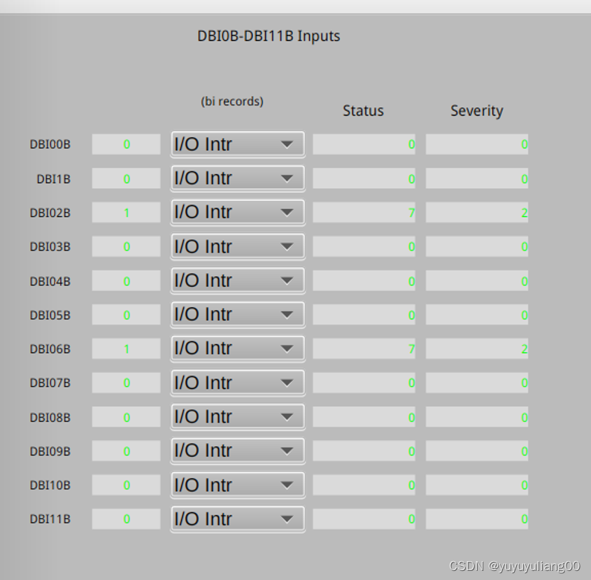
MOXA-E2210:DBI00B~MOXA-E2210:DBI11B分别对应读单个离散输入,这些离散输入地址从10000开始到10011的地址位。
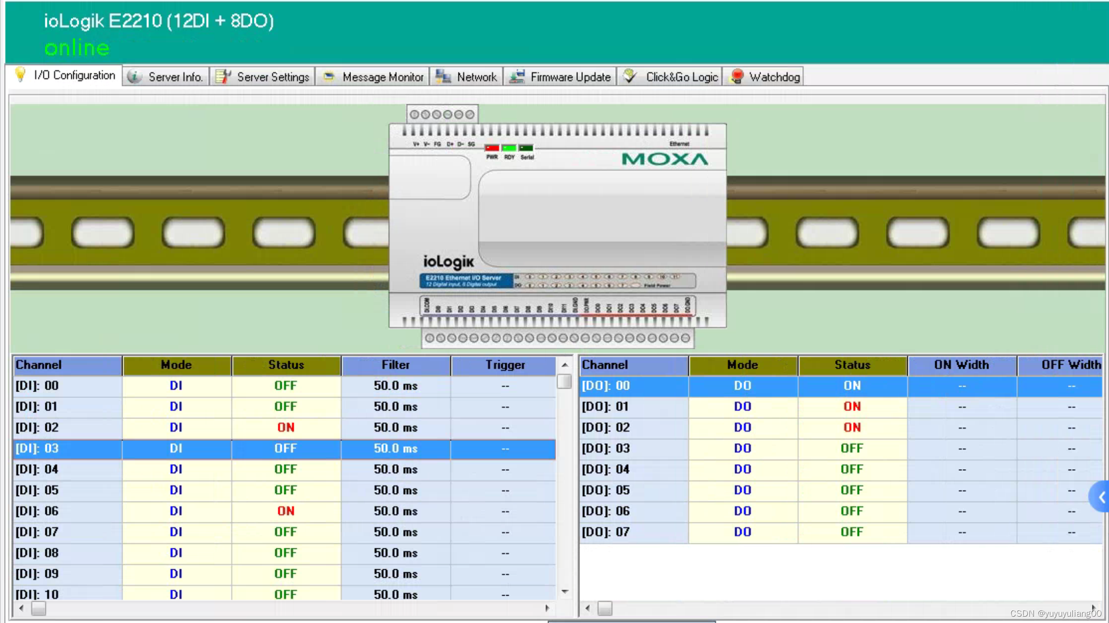
用moxa ioAdmin软件查看moxa iologik e2210的数字输出和数字输入的状态,如下:
用通道访问可以操作和读取输出线圈状态和读取离散输入状态,进行验证:
1) 读入地址为10000,10001,10002和10006的离散输入:
[blctrl@main-machine ioce2210]$ caget MOXA-E2210:DBI00B MOXA-E2210:DBI01B MOXA-E2210:DBI02B MOXA-E2210:DBI06B
MOXA-E2210:DBI00B              Low
MOXA-E2210:DBI01B              Low
MOXA-E2210:DBI02B              High
MOXA-E2210:DBI06B              High
2) 写地址为0,1的线圈,使其闭合,写地址为3,5的线圈,使其断开:
[blctrl@main-machine ioce2210]$ caput MOXA-E2210:BO00B 0
Old : MOXA-E2210:BO00B High
New : MOXA-E2210:BO00B Low
[blctrl@main-machine ioce2210]$ caput MOXA-E2210:BO01B 0
Old : MOXA-E2210:BO01B High
New : MOXA-E2210:BO01B Low
[blctrl@main-machine ioce2210]$ caput MOXA-E2210:BO03B 1
Old : MOXA-E2210:BO03B Low
New : MOXA-E2210:BO03B High
[blctrl@main-machine ioce2210]$ caput MOXA-E2210:BO05B 1
Old : MOXA-E2210:BO05B Low
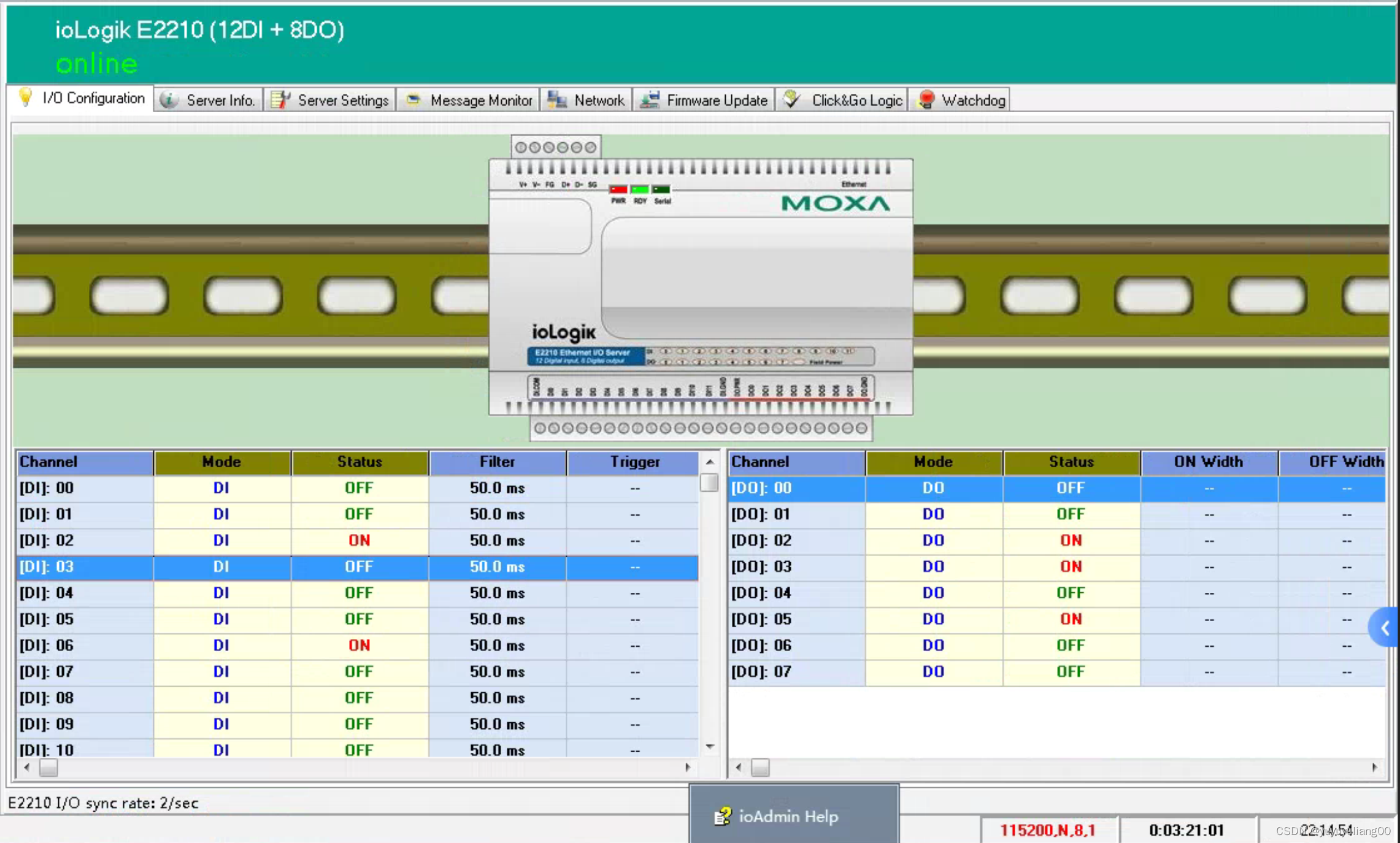
New : MOXA-E2210:BO05B High用ioAdmin观察数字输出的状态为:
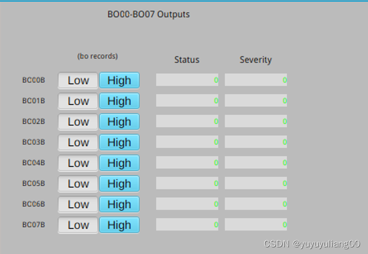
可以用Control System Stdio把以上操作集成到一个图形界面中,操作将更加直观:
1) 控制八个数字输出的操作界面,点击不同线圈对应的Low和High按钮,就可以闭合和断开各自的线圈:
2) 读取12个数字输入的操作界面,当相应数字输入的状态发生变化,就能显示在这个窗口中: