拥有4个edma(Enhanced Direct Memory Access)增强型直接内存访问,

4个edma总共有96个通道, 2个分别有32和16个通道,

以spi为例,可使用dma通道,配置寄存器
dts配置,有TX和RX的配置,有下面两种配置方法:
lpspi3: lpspi@5a030000 {
	compatible = "fsl,imx7ulp-spi";
	reg = <0x0 0x5a030000 0x0 0x10000>;
	interrupts = <GIC_SPI 219 IRQ_TYPE_LEVEL_HIGH>;
	interrupt-parent = <&gic>;
	clocks = <&clk IMX8QXP_SPI3_CLK>,
				<&clk IMX8QXP_SPI3_IPG_CLK>;
	clock-names = "per", "ipg";
	assigned-clocks = <&clk IMX8QXP_SPI3_CLK>;
	assigned-clock-rates = <20000000>;
	power-domains = <&pd_dma2_chan7>;
	dma-names = "tx","rx";
	dmas = <&edma2 7 0 0>, <&edma2 6 0 1>;
	status = "disabled";
};

			pd_dma_lpspi3: PD_DMA_SPI_3 {
				reg = <SC_R_SPI_3>;
				#power-domain-cells = <0>;
				power-domains = <&pd_dma>;
				wakeup-irq = <339>;

				pd_dma2_chan6: PD_LPSPI3_RX {
					reg = <SC_R_DMA_2_CH6>;
					power-domains =<&pd_dma_lpspi3>;
					#power-domain-cells = <0>;
					#address-cells = <1>;
					#size-cells = <0>;

					pd_dma2_chan7: PD_LPSPI3_TX {
						reg = <SC_R_DMA_2_CH7>;
						power-domains =<&pd_dma2_chan6>;
						#power-domain-cells = <0>;
						#address-cells = <1>;
						#size-cells = <0>;
					};
				};
			};
lpspi3: lpspi@5a030000 {
compatible = "fsl,imx7ulp-spi";
reg = <0x0 0x5a030000 0x0 0x10000>;
interrupts = <GIC_SPI 219 IRQ_TYPE_LEVEL_HIGH>;
interrupt-parent = <&gic>;
clocks = <&clk IMX8QXP_SPI3_CLK>,
<&clk IMX8QXP_SPI3_IPG_CLK>;
clock-names = "per", "ipg";
assigned-clocks = <&clk IMX8QXP_SPI3_CLK>;
assigned-clock-rates = <20000000>;
power-domains = <&pd_dma_lpspi3>;
dma-names = "tx","rx";
dmas = <&edma2 7 0 0>, <&edma2 6 0 1>;
status = "okay";
};
pd_dma_lpspi3: PD_DMA_SPI_3 {
reg = <SC_R_SPI_3>;
#power-domain-cells = <0>;
power-domains = <&pd_dma>;
};
edma 0到3的区别:

edma3 16个,edma2 32个(用于SPI和UART),edma1 16个,edma0 32个(SAI)。
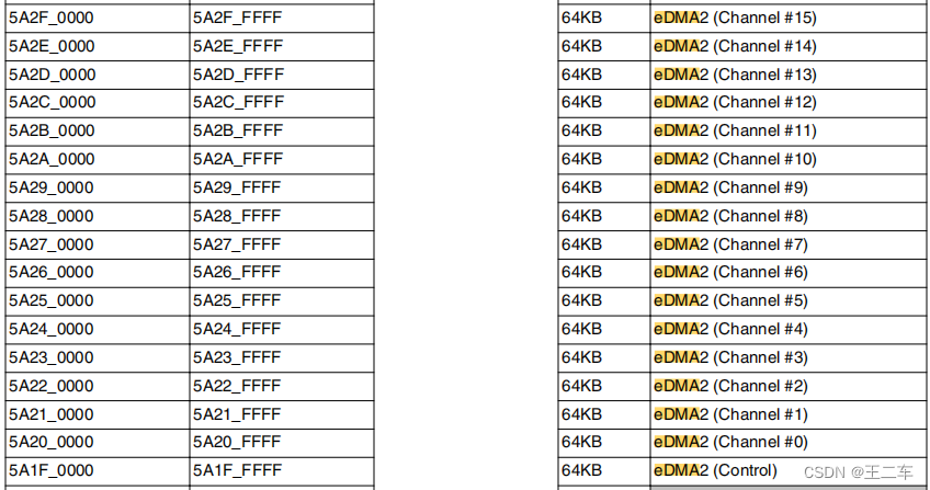
    edma2: dma-controller@5a1f0000 {
        compatible = "fsl,imx8qm-edma";
        reg = <0x0 0x5a200000 0x0 0x10000>, /* channel0 LPSPI0 rx */
              <0x0 0x5a210000 0x0 0x10000>, /* channel1 LPSPI0 tx */
              <0x0 0x5a220000 0x0 0x10000>, /* channel2 LPSPI1 rx */
              <0x0 0x5a230000 0x0 0x10000>, /* channel3 LPSPI1 tx */
              <0x0 0x5a240000 0x0 0x10000>, /* channel4 LPSPI2 rx */
              <0x0 0x5a250000 0x0 0x10000>, /* channel5 LPSPI2 tx */
              <0x0 0x5a260000 0x0 0x10000>, /* channel6 LPSPI3 rx */
              <0x0 0x5a270000 0x0 0x10000>, /* channel7 LPSPI3 tx */
              <0x0 0x5a280000 0x0 0x10000>, /* channel8 UART0 rx */
              <0x0 0x5a290000 0x0 0x10000>, /* channel9 UART0 tx */
              <0x0 0x5a2a0000 0x0 0x10000>, /* channel10 UART1 rx */
              <0x0 0x5a2b0000 0x0 0x10000>, /* channel11 UART1 tx */
              <0x0 0x5a2c0000 0x0 0x10000>, /* channel12 UART2 rx */
              <0x0 0x5a2d0000 0x0 0x10000>, /* channel13 UART2 tx */
              <0x0 0x5a2e0000 0x0 0x10000>, /* channel14 UART3 rx */
              <0x0 0x5a2f0000 0x0 0x10000>; /* channel15 UART3 tx */
        #dma-cells = <3>;
        dma-channels = <16>;
        interrupts = <GIC_SPI 416 IRQ_TYPE_LEVEL_HIGH>,
                 <GIC_SPI 417 IRQ_TYPE_LEVEL_HIGH>,
                 <GIC_SPI 418 IRQ_TYPE_LEVEL_HIGH>,
                 <GIC_SPI 419 IRQ_TYPE_LEVEL_HIGH>,
                 <GIC_SPI 420 IRQ_TYPE_LEVEL_HIGH>,
                 <GIC_SPI 421 IRQ_TYPE_LEVEL_HIGH>,
                 <GIC_SPI 422 IRQ_TYPE_LEVEL_HIGH>,
                 <GIC_SPI 423 IRQ_TYPE_LEVEL_HIGH>,
                 <GIC_SPI 434 IRQ_TYPE_LEVEL_HIGH>,
                 <GIC_SPI 435 IRQ_TYPE_LEVEL_HIGH>,
                 <GIC_SPI 436 IRQ_TYPE_LEVEL_HIGH>,
                 <GIC_SPI 437 IRQ_TYPE_LEVEL_HIGH>,
                 <GIC_SPI 438 IRQ_TYPE_LEVEL_HIGH>,
                 <GIC_SPI 439 IRQ_TYPE_LEVEL_HIGH>,
                 <GIC_SPI 440 IRQ_TYPE_LEVEL_HIGH>,
                 <GIC_SPI 441 IRQ_TYPE_LEVEL_HIGH>;
        interrupt-names = "edma2-chan0-rx", "edma2-chan1-tx",
                  "edma2-chan2-rx", "edma2-chan3-tx",
                  "edma2-chan4-rx", "edma2-chan5-tx",
                  "edma2-chan6-rx", "edma2-chan7-tx",
                  "edma2-chan8-rx", "edma2-chan9-tx",
                  "edma2-chan10-rx", "edma2-chan11-tx",
                  "edma2-chan12-rx", "edma2-chan13-tx",
                  "edma2-chan14-rx", "edma2-chan15-tx";
        pdomains = <&pd_dma2_chan0>, <&pd_dma2_chan1>,/* lpspi0 */
               <&pd_dma2_chan2>, <&pd_dma2_chan3>,/* lpspi1 */
               <&pd_dma2_chan4>, <&pd_dma2_chan5>,/* lpspi2 */
               <&pd_dma2_chan6>, <&pd_dma2_chan7>,/* lpspi3 */
               <&pd_dma2_chan8>, <&pd_dma2_chan9>,/* UART0 */
               <&pd_dma2_chan10>, <&pd_dma2_chan11>,/* UART1 */
               <&pd_dma2_chan12>, <&pd_dma2_chan13>,/* UART2 */
               <&pd_dma2_chan14>, <&pd_dma2_chan15>;/* UART3 */
        status = "okay";
    };
spi dma代码流程
fsl_lpspi_probe
fsl_lpspi_dma_init
controller->transfer_one = fsl_lpspi_transfer_one;
fsl_lpspi_dma_init
controller->dma_tx = dma_request_slave_channel_reason(dev, "tx");
controller->dma_rx = dma_request_slave_channel_reason(dev, "rx");
controller->can_dma = fsl_lpspi_can_dma;
controller->max_dma_len = FSL_LPSPI_MAX_EDMA_BYTES; ((1 << 15) - 1)
fsl_lpspi_transfer_one
fsl_lpspi_setup_transfer
if (fsl_lpspi_can_dma(controller, spi, t))
fsl_lpspi->usedma = 1;
else
fsl_lpspi->usedma = 0;
fsl_lpspi_can_dma
bytes_per_word = fsl_lpspi_bytes_per_word(transfer->bits_per_word);
if (bytes_per_word != 1 && bytes_per_word != 2 && bytes_per_word != 4)【8/16/32 bits_per_word发送使用DMA,范围应该在8~32bit】
return false;
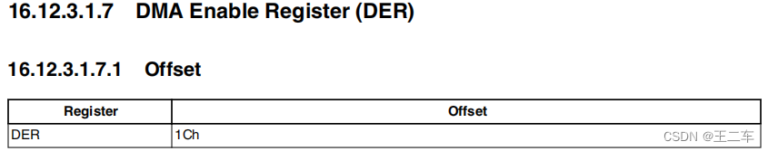
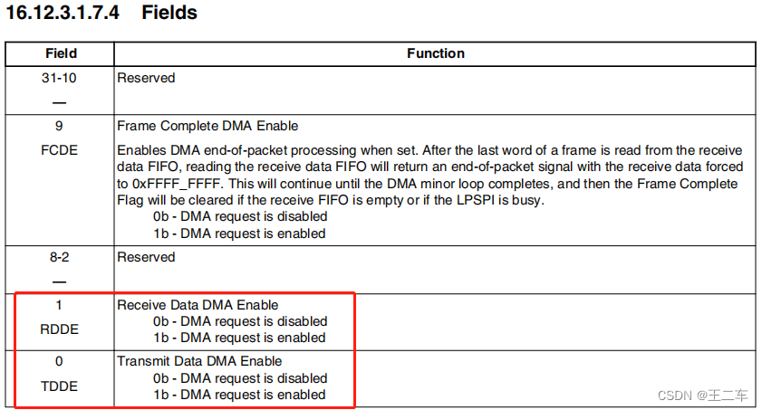
fsl_lpspi_config
if (fsl_lpspi->usedma)
temp = DER_TDDE | DER_RDDE;
writel(temp, fsl_lpspi->base + IMX7ULP_DER);
另一个比较重要的成员是bits_per_word。这个成员指定每次读写的字长,单位是比特。虽然大部分SPI接口的字长是8或者16,仍然会有一些特殊的例子。需要说明的是,如果这个成员为零的话,默认使用8作为字长。
fsl_lpspi_set_cmd
设置bpw,mode
if (fsl_lpspi->usedma)
ret = fsl_lpspi_dma_transfer(controller, fsl_lpspi, t);
else
ret = fsl_lpspi_pio_transfer(controller, t);
fsl_lpspi_dma_transfer
fsl_lpspi_dma_configure
buswidth = DMA_SLAVE_BUSWIDTH_1_BYTE;
tx.direction = DMA_MEM_TO_DEV;
tx.dst_addr = fsl_lpspi->base_phys + IMX7ULP_TDR;
tx.dst_addr_width = buswidth;
tx.dst_maxburst = 1;
ret = dmaengine_slave_config(controller->dma_tx, &tx); 疑问:
1、发送数据可选择使用DMA方式,接收数据是使用中断的形势+dma方式吗?
DMA测试:
1、发送数据,设置bits_per_word=8/16/32,查看cpu使用率,设置12/20对比发送的总体系统时间,加内核函数打印。
2、接收数据,一样的测试。