openGL系列文章目录
前言
最近在学习曲面细分着色器时感觉很多问题没有搞懂,现在回过头来看看openGL渲染管线流程,有一种豁然开朗的感觉:原来之前学的openGL渲染管线流程,自己一直都没学懂啊。。。。。。哎,没关系,现在从头再学一遍。
一、openGL官方渲染管线流程
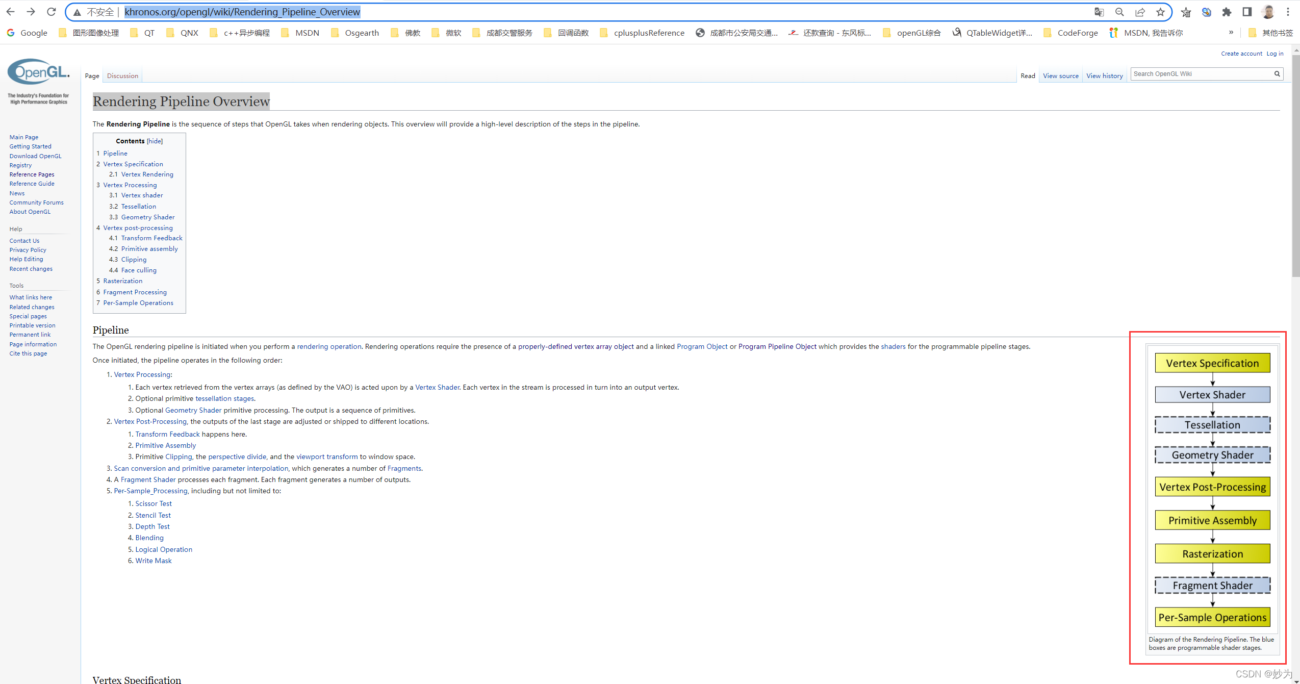
个人感觉:这篇文档最精髓的当属右下角的流程图:
来个特写:_
二、openGL渲染管线路程详解
1.英文原版
Rendering Pipeline Overview
Jump to navigationJump to search
The Rendering Pipeline is the sequence of steps that OpenGL takes when rendering objects. This overview will provide a high-level description of the steps in the pipeline.
Contents
1 Pipeline
2 Vertex Specification
2.1 Vertex Rendering
3 Vertex Processing
3.1 Vertex shader
3.2 Tessellation
3.3 Geometry Shader
4 Vertex post-processing
4.1 Transform Feedback
4.2 Primitive assembly
4.3 Clipping
4.4 Face culling
5 Rasterization
6 Fragment Processing
7 Per-Sample Operations
Pipeline
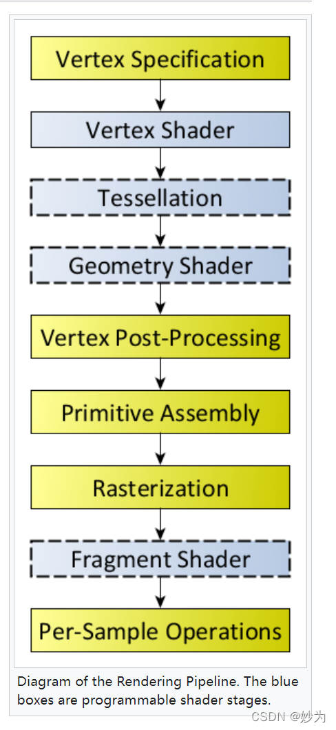
Rendering Pipeline Flowchart
Diagram of the Rendering Pipeline. The blue boxes are programmable shader stages.
The OpenGL rendering pipeline is initiated when you perform a rendering operation. Rendering operations require the presence of a properly-defined vertex array object and a linked Program Object or Program Pipeline Object which provides the shaders for the programmable pipeline stages.
Once initiated, the pipeline operates in the following order:
Vertex Processing:
Each vertex retrieved from the vertex arrays (as defined by the VAO) is acted upon by a Vertex Shader. Each vertex in the stream is processed in turn into an output vertex.
Optional primitive tessellation stages.
Optional Geometry Shader primitive processing. The output is a sequence of primitives.
Vertex Post-Processing, the outputs of the last stage are adjusted or shipped to different locations.
Transform Feedback happens here.
Primitive Assembly
Primitive Clipping, the perspective divide, and the viewport transform to window space.
Scan conversion and primitive parameter interpolation, which generates a number of Fragments.
A Fragment Shader processes each fragment. Each fragment generates a number of outputs.
Per-Sample_Processing, including but not limited to:
Scissor Test
Stencil Test
Depth Test
Blending
Logical Operation
Write Mask
Vertex Specification
Main article: Vertex Specification
The process of vertex specification is where the application sets up an ordered list of vertices to send to the pipeline. These vertices define the boundaries of a primitive.
Primitives are basic drawing shapes, like triangles, lines, and points. Exactly how the list of vertices is interpreted as primitives is handled via a later stage.
This part of the pipeline deals with a number of objects like Vertex Array Objects and Vertex Buffer Objects. Vertex Array Objects define what data each vertex has, while Vertex Buffer Objects store the actual vertex data itself.
A vertex’s data is a series of attributes. Each attribute is a small set of data that the next stage will do computations on. While a set of attributes do specify a vertex, there is nothing that says that part of a vertex’s attribute set needs to be a position or normal. Attribute data is entirely arbitrary; the only meaning assigned to any of it happens in the vertex processing stage.
Vertex Rendering
Main article: Vertex Rendering
Once the vertex data is properly specified, it is then rendered as a Primitive via a drawing command.
Vertex Processing
Vertices fetched due to the prior vertex rendering stage begin their processing here. The vertex processing stages are almost all programmable operations. This allows user code to customize the way vertices are processed. Each stage represents a different kind of shader operation.
Many of these stages are optional.
Vertex shader
Main article: Vertex Shader
Vertex shaders perform basic processing of each individual vertex. Vertex shaders receive the attribute inputs from the vertex rendering and converts each incoming vertex into a single outgoing vertex based on an arbitrary, user-defined program.
Vertex shaders can have user-defined outputs, but there is also a special output that represents the final position of the vertex. If there are no subsequent vertex processing stages, vertex shaders are expected to fill in this position with the clip-space position of the vertex, for rendering purposes.
One limitation on vertex processing is that each input vertex must map to a specific output vertex. And because vertex shader invocations cannot share state between them, the input attributes to output vertex data mapping is 1:1. That is, if you feed the exact same attributes to the same vertex shader in the same primitive, you will get the same output vertex data. This gives implementations the right to optimize vertex processing; if they can detect that they’re about to process a previously processed vertex, they can use the previously processed data stored in a post-transform cache. Thus they do not have to run the vertex processing on that data again.
Vertex shaders are not optional.
Tessellation
Tessellation
Core in version 4.6
Core since version 4.0
Core ARB extension ARB_tessellation_shader
Main article: Tessellation Shader
Primitives can be tessellated using two shader stages and a fixed-function tessellator between them. The Tessellation Control Shader (TCS) stage comes first, and it determines the amount of tessellation to apply to a primitive, as well as ensuring connectivity between adjacent tessellated primitives. The Tessellation Evaluation Shader (TES) stage comes last, and it applies the interpolation or other operations used to compute user-defined data values for primitives generated by the fixed-function tessellation process.
Tessellation as a process is optional. Tessellation is considered active if a TES is active. The TCS is optional, but a TCS can only be used alongside a TES.
Geometry Shader
Main article: Geometry Shader
Geometry shaders are user-defined programs that process each incoming primitive, returning zero or more output primitives.
The input primitives for geometry shaders are the output primitives from a subset of the Primitive Assembly process. So if you send a triangle strip as a single primitive, what the geometry shader will see is a series of triangles.
However, there are a number of input primitive types that are defined specifically for geometry shaders. These adjacency primitives give GS’s a larger view of the primitives; they provide access to vertices of primitives adjacent to the current one.
The output of a GS is zero or more simple primitives, much like the output of primitive assembly. The GS is able to remove primitives, or tessellate them by outputting many primitives for a single input. The GS can also tinker with the vertex values themselves, either doing some of the work for the vertex shader, or just to interpolate the values when tessellating them. Geometry shaders can even convert primitives to different types; input point primitives can become triangles, or lines can become points.
Geometry shaders are optional.
Vertex post-processing
Main article: Vertex Post-Processing
After the shader-based vertex processing, vertices undergo a number of fixed-function processing steps.
Transform Feedback
Main article: Transform Feedback
The outputs of the geometry shader or primitive assembly are written to a series of buffer objects that have been setup for this purpose. This is called transform feedback mode; it allows the user to transform data via vertex and geometry shaders, then hold on to that data for use later.
The data output into the transform feedback buffer is the data from each primitive emitted by this step.
Primitive assembly
Main article: Primitive Assembly
Primitive assembly is the process of collecting a run of vertex data output from the prior stages and composing it into a sequence of primitives. The type of primitive the user rendered with determines how this process works.
The output of this process is an ordered sequence of simple primitives (lines, points, or triangles). If the input is a triangle strip primitive containing 12 vertices, for example, the output of this process will be 10 triangles.
If tessellation or geometry shaders are active, then a limited form of primitive assembly is executed before these Vertex Processing stages. This is used to feed those particular shader stages with individual primitives, rather than a sequence of vertices.
The rendering pipeline can also be aborted at this stage. This allows the use of Transform Feedback operations, without having to actually render something.
Clipping
Main article: Clipping
The primitives are then clipped. Clipping means that primitives that lie on the boundary between the inside of the viewing volume and the outside are split into several primitives, such that the entire primitive lies in the volume. Also, the last Vertex Processing shader stage can specify user-defined clipping operations, on a per-vertex basis.
The vertex positions are transformed from clip-space to window space via the Perspective Divide and the Viewport Transform.
Face culling
Main article: Face Culling
Triangle primitives can be culled (ie: discarded without rendering) based on the triangle’s facing in window space. This allows you to avoid rendering triangles facing away from the viewer. For closed surfaces, such triangles would naturally be covered up by triangles facing the user, so there is never any need to render them. Face culling is a way to avoid rendering such primitives.
Rasterization
Main article: Rasterization
Primitives that reach this stage are then rasterized in the order in which they were given. The result of rasterizing a primitive is a sequence of Fragments.
A fragment is a set of state that is used to compute the final data for a pixel (or sample if multisampling is enabled) in the output framebuffer. The state for a fragment includes its position in screen-space, the sample coverage if multisampling is enabled, and a list of arbitrary data that was output from the previous vertex or geometry shader.
This last set of data is computed by interpolating between the data values in the vertices for the fragment. The style of interpolation is defined by the shader that outputed those values.
Fragment Processing
Main article: Fragment Shader
The data for each fragment from the rasterization stage is processed by a fragment shader. The output from a fragment shader is a list of colors for each of the color buffers being written to, a depth value, and a stencil value. Fragment shaders are not able to set the stencil data for a fragment, but they do have control over the color and depth values.
Fragment shaders are optional. If you render without a fragment shader, the depth (and stencil) values of the fragment get their usual values. But the value of all of the colors that a fragment could have are undefined. Rendering without a fragment shader is useful when rendering only a primitive’s default depth information to the depth buffer, such as when performing Occlusion Query tests.
Per-Sample Operations
Main article: Per-Sample_Processing
The fragment data output from the fragment processor is then passed through a sequence of steps.
The first step is a sequence of culling tests; if a test is active and the fragment fails the test, the underlying pixels/samples are not updated (usually). Many of these tests are only active if the user activates them. The tests are:
Pixel ownership test: Fails if the fragment’s pixel is not “owned” by OpenGL (if another window is overlapping with the GL window). Always passes when using a Framebuffer Object. Failure means that the pixel contains undefined values.
Scissor Test: When enabled, the test fails if the fragment’s pixel lies outside of a specified rectangle of the screen.
Stencil Test: When enabled, the test fails if the stencil value provided by the test does not compare as the user specifies against the stencil value from the underlying sample in the stencil buffer. Note that the stencil value in the framebuffer can still be modified even if the stencil test fails (and even if the depth test fails).
Depth Test: When enabled, the test fails if the fragment’s depth does not compare as the user specifies against the depth value from the underlying sample in the depth buffer.
Note: Though these are specified to happen after the Fragment Shader, they can be made to happen before the fragment shader under certain conditions. If they happen before the FS, then any culling of the fragment will also prevent the fragment shader from executing, this saving performance.
After this, color blending happens. For each fragment color value, there is a specific blending operation between it and the color already in the framebuffer at that location. Logical Operations may also take place in lieu of blending, which perform bitwise operations between the fragment colors and framebuffer colors.
Lastly, the fragment data is written to the framebuffer. Masking operations allow the user to prevent writes to certain values. Color, depth, and stencil writes can be masked on and off; individual color channels can be masked as well.
Category: General OpenGL
2.中文翻译:
因为这里整个渲染管线流程都可以拿一本书来讲解了,我这里翻译了一个概述。
渲染管道概述
渲染管道是OpenGL在渲染对象时所采取的一系列步骤。本概述将对管道中的步骤进行高级描述。
目录
1管道
2顶点说明
2.1顶点渲染
3.顶点处理
3.1顶点着色器
3.2细分
3.3几何体着色器
4.顶点后处理
4.1变换(MVP)—自己理解
4.2基本装配
4.3剪辑
4.4人脸剔除
5光栅化
6片段处理
每个样本操作7次
管道
渲染管道流程图
渲染管道的示意图。蓝色框是可编程的着色器阶段。
OpenGL渲染管道在执行渲染操作时启动。渲染操作需要存在正确定义的顶点阵列对象和链接的程序对象或程序管道对象,该对象为可编程管道阶段提供着色器。
一旦启动,管道将按以下顺序运行:
顶点处理:
从顶点数组(由VAO定义)检索的每个顶点都由顶点着色器作用。流中的每个顶点依次处理为输出顶点。
可选的基本镶嵌阶段。
可选的几何体着色器原语处理。输出是一系列基本体。
顶点后处理,最后阶段的输出被调整或运送到不同的位置。
转换反馈发生在这里。
基本装配
基本体剪裁、透视分割和视口变换到窗口空间。
扫描转换和原始参数插值,生成大量碎片。
片段着色器处理每个片段。每个片段都会生成许多输出。
每样加工,包括但不限于:
剪切测试
模板测试
深度测试
混合
逻辑运算
写掩码
总结
这张图实在太重要,忍不住又复制粘贴一次 _
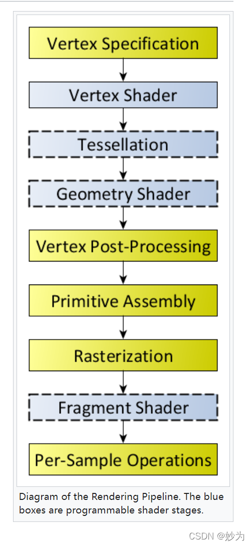
1.渲染管线处理一系列步骤:
(1)Vertex Specification
顶点说明:一般是在c++程序中定义顶点数组,比方说从3dmaxs等等建模软件生成的顶点数据,c++需要把这些顶点数组传给顶点着色器。c++程序cpu处理顶点数组,通过cpu和gpu之间的总线传递。
2.Vertex shader
顶点着色器:顶点着色器接收从c++程序传入的顶点数组,当然,顶点着色器也可以直接自己定义顶点数组,这样就不需要c++程序传入顶点数组了。
-
Tessellation
这里是曲面细分着色器:
(1)曲面细分控制着色器;
(2)曲面细分器;
(3)曲面细分评估着色器。
在这里一般都会写:曲面细分控制着色器和曲面细分评估着色器这两个着色器程序 -
Geometry Shader
几何着色器:与曲面细分一样,几何着色器使程序员能够以顶点着色器中无法实现的方式操纵顶点
组。在某些情况下,可以使用曲面细分着色器或者几何着色器完成同样的任务,因为它们的功能在某些方面重叠。 -
Vertex Post-Processing
转换反馈发生在这里。
基本装配
基本体剪裁、透视分割和视口变换到窗口空间。 -
Rasterization
最终,我们3D 世界中的点、三角形、颜色等全都需要展现在一个2D 显示器上。这个2D 屏幕由光栅——矩形像素阵列组成。当3D 物体光栅化后,OpenGL 将物体中的图元(通常是三角形)转化为片段。片段拥有关于像素的信息。光栅化过程确定了用以显示3 个顶点所确定的三角形的所有像素需要绘制的位置。光栅化过程开始时先对三角形的每对顶点进行插值。插值过程可以通过选项调节。就目前而言,使用图2.9 所示的简单的线性插值就够了。原本的3 个顶点标记为红色(见彩插)。如果光栅化过程到此为止,那么呈现出的图像将会是线框模型。呈现线框模型也是OpenGL 中的一个选项。通过在display()函数中glDrawArrays()调用之前添加如下命令:
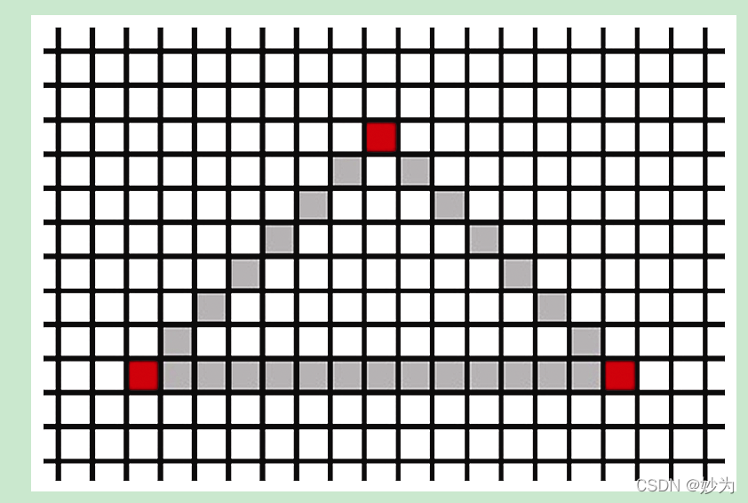
-
Fragment Processing
片段着色器用于为光栅化的像素指定颜色。我们已经在程序2.2 中看到了
片段着色器示例。在程序2.2 中,片段着色器仅将输出硬编码为特定值,从而为每个输出
的像素赋予相同的颜色。不过GLSL 为我们提供了其他计算颜色的方式,用以表现无穷的
创造力。 -
Per-Sample Operations
该阶段的输入就是片段,在该阶段会进行一些测试,比如使用深度测试(depth test,通常也称作z缓存)和模板测试(stencil test)来决定一个片元是否可见。这些测试需要用户激活 才会被触发。
如果一个片元的成功通过了所有激活的测试,它就可以直接被绘制到帧缓存中,它对应的像素值,深度值会相应的更新。如果开启了blending模式,那么该片元的颜色会与该像素当前的颜色相叠加,形成新的颜色值并写入帧缓存。