硬件测试平台:正点原子潘多拉STM32L4开发板
内核版本:4.0.0
注意:下面的示例代码是从原子提供的例程中摘录,因此可能与最新的RT-Thread源码有出入(因为RT-Thread源码在不断的开发维护中)
首先看main.c,可见main函数主要实现了LED闪烁,以及打印LED状态的功能
#include <rtthread.h>
#include <rtdevice.h>
#include <board.h>

/* using RED LED in RGB */
#define LED_PIN              PIN_LED_R

int main(void)
{


    unsigned int count = 1;
    /* set LED pin mode to output */
    rt_pin_mode(LED_PIN, PIN_MODE_OUTPUT);

    while (count > 0)
    {


        /* led on */
        rt_pin_write(LED_PIN, PIN_LOW);
        rt_kprintf("led on, count: %d\n", count);
        rt_thread_mdelay(500);

        /* led off */
        rt_pin_write(LED_PIN, PIN_HIGH);
        rt_kprintf("led off\n");
        rt_thread_mdelay(500);

        count++;
    }

    return 0;
}
PIN_LED_R在硬件驱动层的drv_gpio.h中定义了
#define PIN_LED_R 38 // PE7 : LED_R --> LED
剖析顺序从上到下,从应用层深入到驱动层。(pin驱动相关的源文件主要包括drv_gpio.c 、pin.c、 device.c)
代码框架如下图:
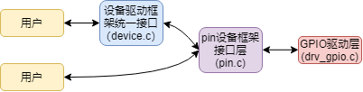
接口层的pin.c往上对接用户,往下对接底层驱动。
对于不同芯片,用户层的接口是统一的,而对于驱动层来说,只需要对接好相应的回调函数。
通过统一的接口,应用开发不需要知道底层驱动,减少重复造轮子的时间。
按照点灯裸机的编程思路,先是开启GPIO时钟,然后初始化控制LED的GPIO为输出,最后写GPIO输出高或低电平,main函数中先是rt_pin_mode函数,从字面上看也知道这是设置pin工作模式。下面追踪代码:
/* RT-Thread Hardware PIN APIs */
void rt_pin_mode(rt_base_t pin, rt_base_t mode)
{


    RT_ASSERT(_hw_pin.ops != RT_NULL); //断言 检查_hw_pin.ops不为空
    _hw_pin.ops->pin_mode(&_hw_pin.parent, pin, mode);
}
结构体_hw_pin 定义在pin.c中
static struct rt_device_pin _hw_pin;
追踪struct rt_device_pin 这个类型
/* pin device and operations for RT-Thread */
struct rt_device_pin
{


    struct rt_device parent;
    const struct rt_pin_ops *ops;
};

//在rtdef.h
/**
 * Device structure
 */
struct rt_device
{


    struct rt_object          parent;                   /**< inherit from rt_object */

    enum rt_device_class_type type;                     /**< device type */
    rt_uint16_t               flag;                     /**< device flag */
    rt_uint16_t               open_flag;                /**< device open flag */

    rt_uint8_t                ref_count;                /**< reference count */
    rt_uint8_t                device_id;                /**< 0 - 255 */

    /* device call back */
    rt_err_t (*rx_indicate)(rt_device_t dev, rt_size_t size);
    rt_err_t (*tx_complete)(rt_device_t dev, void *buffer);

#ifdef RT_USING_DEVICE_OPS
    const struct rt_device_ops *ops;
#else
    /* common device interface */
    rt_err_t  (*init)   (rt_device_t dev);
    rt_err_t  (*open)   (rt_device_t dev, rt_uint16_t oflag);
    rt_err_t  (*close)  (rt_device_t dev);
    rt_size_t (*read)   (rt_device_t dev, rt_off_t pos, void *buffer, rt_size_t size);
    rt_size_t (*write)  (rt_device_t dev, rt_off_t pos, const void *buffer, rt_size_t size);
    rt_err_t  (*control)(rt_device_t dev, int cmd, void *args);
#endif

#if defined(RT_USING_POSIX)
    const struct dfs_file_ops *fops;
    struct rt_wqueue wait_queue;
#endif

    void                     *user_data;                /**< device private data */
};

//在pin.h
struct rt_pin_ops
{


    void (*pin_mode)(struct rt_device *device, rt_base_t pin, rt_base_t mode);
    void (*pin_write)(struct rt_device *device, rt_base_t pin, rt_base_t value);
    int (*pin_read)(struct rt_device *device, rt_base_t pin);

    /* TODO: add GPIO interrupt */
    rt_err_t (*pin_attach_irq)(struct rt_device *device, rt_int32_t pin,
                      rt_uint32_t mode, void (*hdr)(void *args), void *args);
    rt_err_t (*pin_detach_irq)(struct rt_device *device, rt_int32_t pin);
    rt_err_t (*pin_irq_enable)(struct rt_device *device, rt_base_t pin, rt_uint32_t enabled);
};
struct rt_device_pin 这个类型中的成员ops,是接口层与硬件驱动层的媒介。
从struct rt_pin_ops类型可以看到里面是六个函数指针分别对应设置pin模式,写pin,读pin,以及三个与中断有关的。
那问题是,在哪里把ops变量初始化了,也就是把pin接口层和底层连接起来呢?
在初始化阶段里面实现了
$ Sub $ $main(void) -> rtthread_startup() -> rt_hw_board_init() -> rt_hw_pin_init()
//这是drv_gpio.c的
const static struct rt_pin_ops _stm32_pin_ops =
{


    stm32_pin_mode,
    stm32_pin_write,
    stm32_pin_read,
    stm32_pin_attach_irq,
    stm32_pin_dettach_irq,
    stm32_pin_irq_enable,
};
int rt_hw_pin_init(void)
{


    return rt_device_pin_register("pin", &_stm32_pin_ops, RT_NULL);
}

//这是pin.c的
int rt_device_pin_register(const char *name, const struct rt_pin_ops *ops, void *user_data)
{


    _hw_pin.parent.type         = RT_Device_Class_Miscellaneous;
    _hw_pin.parent.rx_indicate  = RT_NULL;
    _hw_pin.parent.tx_complete  = RT_NULL;

#ifdef RT_USING_DEVICE_OPS
    _hw_pin.parent.ops          = &pin_ops;
#else
    _hw_pin.parent.init         = RT_NULL;
    _hw_pin.parent.open         = RT_NULL;
    _hw_pin.parent.close        = RT_NULL;
    _hw_pin.parent.read         = _pin_read;
    _hw_pin.parent.write        = _pin_write;
    _hw_pin.parent.control      = _pin_control;
#endif

    _hw_pin.ops                 = ops;   //这里把_stm32_pin_ops和 _hw_pin.ops 连接起来了
    _hw_pin.parent.user_data    = user_data;

    /* register a character device */
    rt_device_register(&_hw_pin.parent, name, RT_DEVICE_FLAG_RDWR);

    return 0;
}
从上面的代码可以看出,底层驱动只要实现_stm32_pin_ops 里的6个接口函数即可。
点灯主要关注stm32_pin_mode和stm32_pin_write这两个函数:(这都是在驱动层也就是drv_gpio.c中)
static void stm32_pin_mode(rt_device_t dev, rt_base_t pin, rt_base_t mode)
{


    const struct pin_index *index;
    GPIO_InitTypeDef GPIO_InitStruct;

    index = get_pin(pin);
    if (index == RT_NULL)
    {


        return;
    }

    /* GPIO Periph clock enable */
    index->rcc();

    /* Configure GPIO_InitStructure */
    GPIO_InitStruct.Pin = index->pin;
    GPIO_InitStruct.Mode = GPIO_MODE_OUTPUT_PP;
    GPIO_InitStruct.Pull = GPIO_NOPULL;
    GPIO_InitStruct.Speed = GPIO_SPEED_FREQ_HIGH;

    if (mode == PIN_MODE_OUTPUT)
    {


        /* output setting */
        GPIO_InitStruct.Mode = GPIO_MODE_OUTPUT_PP;
        GPIO_InitStruct.Pull = GPIO_NOPULL;
    }
    else if (mode == PIN_MODE_INPUT)
    {


        /* input setting: not pull. */
        GPIO_InitStruct.Mode = GPIO_MODE_INPUT;
        GPIO_InitStruct.Pull = GPIO_NOPULL;
    }
    else if (mode == PIN_MODE_INPUT_PULLUP)
    {


        /* input setting: pull up. */
        GPIO_InitStruct.Mode = GPIO_MODE_INPUT;
        GPIO_InitStruct.Pull = GPIO_PULLUP;
    }
    else if (mode == PIN_MODE_INPUT_PULLDOWN)
    {


        /* input setting: pull down. */
        GPIO_InitStruct.Mode = GPIO_MODE_INPUT;
        GPIO_InitStruct.Pull = GPIO_PULLDOWN;
    }
    else if (mode == PIN_MODE_OUTPUT_OD)
    {


        /* output setting: od. */
        GPIO_InitStruct.Mode = GPIO_MODE_OUTPUT_OD;
        GPIO_InitStruct.Pull = GPIO_NOPULL;
    }

    HAL_GPIO_Init(index->gpio, &GPIO_InitStruct);
}

static void stm32_pin_write(rt_device_t dev, rt_base_t pin, rt_base_t value)
{


    const struct pin_index *index;

    index = get_pin(pin);
    if (index == RT_NULL)
    {


        return;
    }

    HAL_GPIO_WritePin(index->gpio, index->pin, (GPIO_PinState)value);//调用HAL库函数控制GPIO输出高低电平
}
关于stm32_pin_mode函数有一个问题,我们知道GPIO_InitStruct需要初始化四个成员变量分别是选择pin,选择GPIO模式,选择是否加上下拉,选择GPIO速度,上述代码从对上层的通用性考虑(不是每个芯片都可以控制速率等),只往上提供了mode,而速度固定在了GPIO_SPEED_FREQ_HIGH,上拉下拉则根据mode固定变化。如果有特殊需求对某个GPIO要做一些特殊配置,比如要降低某个GPIO的速率以降低功耗,这就得另外去改了。
关于stm32_pin_write()函数单独拉出来看一下:
#define LED_PIN              PIN_LED_R
#define PIN_LED_R     38        // PE7 :  LED_R        --> LED

#define PIN_LOW                 0x00
#define PIN_HIGH                0x01

rt_pin_write(LED_PIN, PIN_LOW);

void rt_pin_write(rt_base_t pin, rt_base_t value)
{


    RT_ASSERT(_hw_pin.ops != RT_NULL);
    _hw_pin.ops->pin_write(&_hw_pin.parent, pin, value); //以上分析我们知道,pin_write实际上就是指向了stm32_pin_write函数
}

static void stm32_pin_write(rt_device_t dev, rt_base_t pin, rt_base_t value)
{


    const struct pin_index *index;

    index = get_pin(pin);
    if (index == RT_NULL)
    {


        return;
    }

    HAL_GPIO_WritePin(index->gpio, index->pin, (GPIO_PinState)value);//调用HAL库函数控制GPIO输出高低电平
}

static void stm32_pin_write(rt_device_t dev, rt_base_t pin, rt_base_t value)
{


    const struct pin_index *index;

    index = get_pin(pin);
    if (index == RT_NULL)
    {


        return;
    }

    HAL_GPIO_WritePin(index->gpio, index->pin, (GPIO_PinState)value);//(GPIO_PinState)这里用了强制转换是防止上层传下来0或1会编译报警
}

#define ITEM_NUM(items) sizeof(items) / sizeof(items[0])
static const struct pin_index *get_pin(uint8_t pin)
{


    const struct pin_index *index;

    if (pin < ITEM_NUM(pins))
    {


        index = &pins[pin];
        if (index->index == -1)
            index = RT_NULL;
    }
    else
    {


        index = RT_NULL;
    }

    return index;
};

static const struct pin_index pins[] =
{


    __STM32_PIN_DEFAULT,
    __STM32_PIN(1, E, 2),       // PE2 :  SAI1_MCLK_A  --> ES8388
    __STM32_PIN(2, E, 3),       // PE3 :  SAI1_SD_B    --> ES8388
    ...//省略
    __STM32_PIN(38, E, 7),      // PE7 :  LED_R        --> LED   //这是我们要用到的红色LED脚
    ...//省略
    __STM32_PIN(98, E, 1),      // PE1 :  IO_PE1       --> EXTERNAL MODULE
    __STM32_PIN_DEFAULT,        //     :  VSS
    __STM32_PIN_DEFAULT,        //     :  VDD
};

/* STM32 GPIO driver */
struct pin_index
{


    int index;
    void (*rcc)(void);
    GPIO_TypeDef *gpio;
    uint32_t pin;
};

//这里用到了##连接符  这个符号在RT-Thread里用得很多
#define __STM32_PIN(index, gpio, gpio_index)                                \
    {                                                                       \
        index, GPIO##gpio##_CLK_ENABLE, GPIO##gpio, GPIO_PIN_##gpio_index   \
    }
调用rt_pin_write时第一个参数传入38实际上就在struct pin_index pins[] 这里面索引到__STM32_PIN(38, E, 7),
查看原理图发现,这个表对应了芯片的引脚序号,比如38脚就是PE7,也就是我们要用的红色LED控制脚
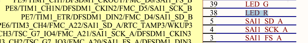
rt_pin_write(38, 1)实际到了底层就是HAL_GPIO_WritePin(GPIOE, GPIO_PIN_7, (GPIO_PinState)1);
//(GPIO_PinState)这里用了强制转换是防止上层传下来0或1会编译报警 细节到位
还剩一个问题,在哪里使能了该GPIO时钟?
在stm32_pin_mode函数里面使能了对应的GPIO时钟,
/* GPIO Periph clock enable */
index->rcc();
rcc是一个函数指针,实际上是执行了 GPIOE_CLK_ENABLE();
全部分析完毕,写完这篇文章大概用时两个小时。
唠一句:
RT-Thread的代码还是不错的,初学者可能会对这种分层思想有点懵,但是实际项目中,这种思想一定要运用起来,只有真正的去解耦合,把应用层和驱动层尽可能分开,才能把应用层的代码做到方便在不同平台移植,这可能把这种工程代码移植一下平台,再对比一下不分层,应用和驱动相互交错的工程移植一下,就明白到底这种编程思想强在哪里了。重复地造轮子只会让你越来越累,降低工作效率。